Abstract. The play-in/play-out approach is a method for specifying ..... Let us explain what a smart execution is: the standard execution called ânaive play-outâ ...
Some Methodological Observations Resulting from Experience Using LSCs and the Play-In/Play-Out Approach ⋆ David Harel, Hillel Kugler and Gera Weiss Department of Computer Science and Applied Mathematics The Weizmann Institute of Science, Rehovot, Israel {David.Harel,Hillel.Kugler,Gera.Weiss}@weizmann.ac.il
Abstract. The play-in/play-out approach is a method for specifying and developing complex reactive systems. It is built upon a scenariobased philosophy, and uses the language of live sequence charts (LSCs) and a support tool called the Play-Engine. We present some conclusions from the initial experience we have had using the approach on several projects, and discuss methodological aspects rising from this experience. The projects are from aviation, telecommunication and system manufacturing domains.
1
Introduction
Understanding system and software behavior by looking at various “stories” or scenarios seems a promising approach, and it has focused intensive research efforts in the last few years. One of the most widely used languages for specifying scenario-based requirements is that of message sequence charts (MSCs), adopted long ago by the ITU [Z1296], or its UML variant, sequence diagrams [UML]. Sequence charts (whether MSCs or their UML variant) possess a rather weak partial-order semantics that does not make it possible to capture many kinds of behavioral requirements of a system. To address this, while remaining within the general spirit of scenario-based visual formalisms, a broad extension of MSCs has been proposed, called live sequence charts (LSCs) [DH01]. LSCs distinguish between behaviors that may happen in the system (existential) from those that must happen (universal). A universal chart contains a prechart, which specifies the scenario which, if successfully executed, forces the system to satisfy the scenario given in the actual chart body. The distinction between mandatory (hot) and provisional (cold) applies also to other LSC constructs, e.g., conditions and locations, thus creating a rich and powerful language, which among many other things can express forbidden behavior (‘anti-scenarios’). ⋆
This research was supported in part by the John von Neumann Minerva Center for the Verification of Reactive Systems, by the European Commission projects OMEGA (IST-2001-33522) and AMETIST (IST-2001-35304) and by the Israel Science Foundation (grant No. 287/02-1).
In [HM03a,HM03b] a methodology for specifying and validating requirements, termed the “play-in/play-out approach” is described. According to this approach, requirements are captured by the user playing in scenarios using a graphical interface of the system to be developed or using an object model diagram. The user “plays” the GUI by clicking buttons, rotating knobs and sending messages (calling functions) to objects in an intuitive manner. By similarly playing the GUI, the user describes the desired reactions of the system and the conditions that may, must or may not hold. As this is being done, the supporting tool, called the Play-Engine, constructs a formal version of the requirements in the form of LSCs. Note that it is not always necessary to spend much time designing a fancy graphical interface. In many cases, it is enough to use a standard object model diagram. Our tool, the Play-Engine, support class diagrams and allows to work with, so called, internal objects that are not reflected in the GUI. Play-out is a complementary idea to play-in, which, rather surprisingly, makes it possible to execute the requirements directly. In play-out, the user simply plays the GUI application as he/she would have done when executing a system model, or the final system implementation, but limiting him/herself to “end-user” and external environment actions only. While doing this, the Play-Engine keeps track of the actions and causes other actions and events to occur as dictated by the universal charts in the specification. Here too, the engine interacts with the GUI application and uses it to reflect the system state at any given moment. This process of the user operating the GUI application and the Play-Engine causing it to react according to the specification has the effect of working with an executable model, but with no intra-object model having to be built or synthesized. The play-in/play-out approach is supported by a prototype tool called the Play-Engine, described in detail in [HM03a]. The approach appears to be useful in many stages in the development of reactive software, including requirements engineering, specification, testing and verification. In the long run it might also pave the way to systems that are constructed directly from their requirements, without the need for intra-object or intra-component modeling or coding.
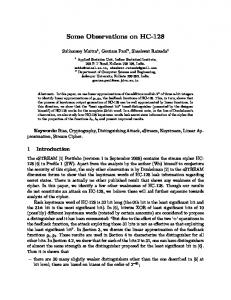
Play-Engine =
Scenarios DB + Input Mechanism + Execution Engine + Analysis Tools (LSCs) (Play-In) (Play-Out) (Smart Play-Out)
Fig. 1. Play-Engine Scheme
Being a new approach that suggests a different way of developing systems, there are many aspects that are not yet fully understood when one attempts to apply the methodology and tools to real-world applications. In this paper we describe the initial experience we have had using the approach on several projects, and discuss methodological aspects arising from this experience. The projects are from aviation, telecommunication and system manufacturing domains. We should add that another important application of the play-in/play-out approach is in modeling biological applications [KHK+ 03], a domain that will not be de-
scribed here but which has also significantly contributed to our methodological experience. This paper is not intended as a technical introduction to LSCs. We instead, try to keep the discussion at a high level, trying to emphasize more general ideas. Although the focus is on working with LSCs, we believe that our observations are relevant to other formalisms and modeling methods.
2
Applications
In this section we briefly overview the applications in which the play-in/play-out approach and Play-Engine tools were applied. This provides an initial idea of what kinds of systems are well fitted to the approach. Later on in the paper, these applications will be used to demonstrate and discuss the methodological issues arising while using the play-in/play-out approach.
2.1
IAI - Sensor voting and monitoring
In this application, provided by the Israeli Aircraft Industry (IAI), a subsystem of a flight control computer in an unmanned air vehicle (UAV) is modeled using LSCs and the Play-Engine. The main role of a flight control computer is to implement control loops of servo actuators controlling the air vehicle surfaces. The computer computations are influenced by the actual values provided periodically by different sensors installed in the air vehicle. To achieve high reliability, a redundancy of sensors and flight control computers is used. A voting and monitoring procedure samples the redundant sensors determining that they are in a reasonable range, disqualifying sensors that are out of range for several consecutive rounds. The communication between the sensors and computers is via a central bus. Timing play a critical role in this application, and among the goals of our work is to prove the correctness of the voting and monitoring algorithm and to suggest optimized time delays that can still guarantee correctness.
2.2
NLR - MARS application
The Medium Altitude Reconnaissance System (MARS) is deployed by the Royal Netherlands Air Force on the F16 aircraft. The system employs two cameras to capture high resolution images, and corrects the image degradation caused by the forward motion of the aircraft. The system is responsible for producing frame annotation, performing health monitoring and alarm processing functions. A high level description of system requirements of a subsystem of MARS dealing with data capturing and processing activities has been modeled using LSCs and the Play-Engine. Again, timing information plays a very important part in the requirements.
2.3
FTRD - Depannage
This application is a telecommunication service called Depannage, provided by France Telecom. The Depannage service allows a user to make a phone call and ask for the help of a doctor, fire brigade, car maintenance, etc. The service invocation software first asks for authentication of the calling user, and then searches for the calling location. Once the calling location is found, the software searches in a data base for numbers of potential service providers corresponding to the Depannage society members in the vicinity of the caller. Once various numbers are found, the service tries to connect the caller to one of the potential called numbers (in a sequential or parallel way). In any case the caller should be connected to a secretary or to a vocal box. In parallel a second logic will make periodic location requests to the Depannage society members in order to record their latest locations in the data base. The Depannage service is implemented as a layered application consisting of several components. Each layer or component is described by a group of scenarios; the connection between layers is very clean and precise. The objects in each layer communicate only among themselves and with the objects in the adjacent layers. This architecture enables applying methodological approaches to break down the complexity of the system as is described later on.
2.4
Cybernetix - Smart-Card manufacturing
This application involves a smart-card personalization machine. For a more comprehensive description see [Alb02]. The personalization machine is a typical production line consisting of a belt that moves artifacts (smart cards) between production stations that handle different aspects of the manufacturing, until at the end of the belt final smart-card products are collected. Cybernetix manufactures machines for smart-card personalization. These machines take piles of blank smart-cards as raw material, program them with personalized data, print and test them. The machines have a throughput of thousands of cards per hour. It is required that the output of cards occurs in a predefined order. Unfortunately, some cards are defective and they have to be discarded, but without changing the output order of personalized cards. Decisions on how to reorganize the flow of cards must be taken within fractions of a second, if no production time is to be lost. The aim of this case study is to model the desired production requirements, the timing requirements of operations of the machine and on this basis synthesize the coordination of the tracking of defective cards. The goal is to maximize the throughput of the machine under certain error assumptions. Another design objective, specified by Cybernetix, is to shorten the machine, i.e., use less slots. This means that we would like to show that it is possible to handle all errors using the minimal number of belt slots.
3 3.1
Methodology How to build the GUI
A central idea in the play-in/play-out approach is that a graphic user interface (GUI) of the system is constructed and then used to specify the requirements in the play-in stage and to show the execution during play-out. How do we go about starting the job of building an appropriate GUI? How do we define the objects and corresponding attributes and methods, that will later be used in play-in/play-out? These questions lead to the observation that there are certain applications for which a graphical representation is natural and straightforward. For these the play-in/play-out approach seems particularly effective. An example is the smart-card manufacturing system described in Section 2.4. The GUI used for this application appears in Fig. 2.
Fig. 2. Smart Card Manufacturing GUI - CYBERNETIX
Our experience showed that building the GUI is a task that should be done carefully, as much as possible considering in advance the scenarios and properties that we later plan to specify and analyze. In a case where several developers and domain experts are involved, early feedback from all participants is crucial. In the IAI application (Section 2.1) such feedback helped in building a model that was natural, useful and relevant to different members of the team. The GUI used for this application appears in Fig. 3. Building the GUI should be considered to be a full-fledged modeling activity, and the GUI should reflect interesting and important parts of the system but not the system in full detail. An iterative approach for developing the GUI can be useful, starting with a simple GUI, playing scenarios in via it and then extending it after gaining better understanding of the application. When refining a GUI in such a manner, for a certain class of changes, e.g., adding new objects or adding a new attribute to an existing object, the tool allows performing the changes in the GUI without the
need to re-play in the already existing scenarios. For more complex changes, such as deleting objects and attributes, the existing scenarios must be re-played on the new GUI. Being a research prototype tool, emphasis was not put on supporting complex GUI refinements in an automatic fashion, but such directions may be explored in future versions of the tool.
Fig. 3. Voting and monitoring GUI - IAI case study
3.2
GUI vs. Internal Objects
Internal objects, described in the form of an object model diagram [UML], can be used to describe objects that do not have a meaningful or convenient graphical representation. The Play-Engine supports describing some of the objects in the GUI and others as internal objects represented in an object model diagram. An example from the FTRD application appears in Fig. 4. In object model diagrams each object is depicted by a box, showing its attributes and methods. During play-out the values of attributes are updated in the diagram as they change, and arrows are drawn dynamically by the PlayEngine to reflect the message
communication between objects. The play-in and play-out processes are fully supported in the Play-Engine for internal objects. This capability also provides an alternative to building a specially tailored GUI, thus saving valuable time. In two of our applications, those of NLR (Section 2.2) and FTRD (Section 2.3), most of the system was described using internal objects, partly due to the fact that the systems were not graphical in nature, and also to allow quick progress to the scenario elucidation phase. This success causes us to believe that using variants of object model diagrams is a practical approach. We expect that better tool support for this, which would allow, for example, the use of multiple diagrams and the application of layout algorithms, would enhance the usage of internal objects. We indeed plan this as part of future versions of the engine.
Fig. 4. Internal objects in the FTRD case study
Although using internal objects and object model diagrams proved practical, we still think that building a GUI is very worthwhile. The ability to work with an executable model reflected in a friendly GUI seems important during project meetings, makes it easier to get feedback and explain issues by the the various members of the team — not only the programmers.
3.3
GUI’s for ever-growing systems
When modeling real-world systems using the Play-Engine, maintaining the complexity of the graphical representation, either the GUI or internal object diagrams becomes quite a challenge. Using a GUI rather than only object diagrams allows a more succinct representation and so enables capturing larger systems. Still, even for GUI’s there is a limitation on the amount of information that can be represented. Recently, the Play-Engine has been extended to support multiple GUI forms. The basic extension allows different objects to be displayed in different GUI forms, thus making it possible to decompose the application into subsystems, maintaining full support for the play-in and play-out activities. A more advanced extension is presented in the recent work on InterPlay [BHM04]. InterPlay is a simulation engine coordinator that supports cooperation and interaction of multiple simulation and execution tools. It enables connecting several Play-Engines and also connecting a statechart-based executable model to the Play-Engine. GUI forms and internal object diagrams can thus be distributed between various Play-Engines, which makes it possible to handle larger systems. These new features have not yet been used in the applications described in this paper, but we hope to use them soon. Our experience in the applications showed that the internal object diagrams are very useful, and we plan to support multiple object diagrams within the same Play-Engine in the future. We believe that experience in other tools that handle large systems in diagrammatic forms is relevant here and in time will be integrated into the Play-Engine tool. 3.4
Large LSCs vs. small ones
One of the methodological questions raised while working on the case studies was whether we should describe scenarios using large LSCs that specify rich behavior or to break the behavior into several smaller LSCs that activate and interact with each other. Although there is no clear answer to this, our experience shows that a single LSC should not be too large and complex, and that understanding the relationship between many smaller LSCs can provide insight into the developed system. We thus suggest that, at least in the initial modeling stages, one should specify smaller LSCs that describe the basic scenarios. In later stages, more complex charts can be constructed either separately, or by composing the basic charts. Our experience also shows that from the perspective of efficient analysis, handling many small and simple charts that can be interleaved in numerous ways is harder, thus for the process of applying smart play-out pre-merging small charts into larger ones has an advantage. At this stage it is still hard to define precisely what is small vs. large when it comes to LSCs, and this probably also depends on the context of the application. However, we believe that being aware of this tradeoff even without a precise definition is important for users of scenario-based approaches. To illustrate the above discussion, we describe our experience with the smart card case study described above. In this case study, a manufacturing machine is modeled. The machine is composed of a belt and stations that put/take cards
from belt slots and sometimes carry some manufacturing steps. To allow modularity, we assigned each station with its own scenarios. This defines reusable objects that can be combined in different ways in order to test various design options for the machine. To improve the performance of the analysis, we merged many small scenarios to one big LSC. This improved the speed of properties validation by several orders of magnitude. In principle, merging charts is a formal process that can be mechanized, e.g., using algorithms developed in [Gil03]. We used both models, interchangeably, depending on which aspect of the system we wanted to examine. 3.5
Refinement of LSCs
The counterexample guided abstraction refinement approach is a known method for model-checking multilayered systems [CGJ+ 00,CGLZ95,Kur95]. It consists of an iterative double phase process. The abstraction phase hides the internal logic of various objects, hence considering them as inputs. This type of abstraction may lead to traces that cannot be simulated on the complete model. The refinement phase consists of checking whether the counterexample is real or spurious. If the example turns out to be incompatible with parts of the model abstracted out, one can refine the abstraction based on the counterexample. The process is repeated until the abstraction is good enough to carry an analysis on the objects that are not abstracted.
Fig. 5. Abstracting the behavior of the Flight Control Computer
This technique is particularly useful for layered models. Layers separation is conveniently facilitated by putting each layer in a different use-case. Occasionally, some interesting analysis involves only one layer so it can be carried out on that
layer only. Other properties can be analyzed progressively by breaking them to separate properties of the layers. The process of abstraction and refinement of LSCs goes as follows. The user chooses a part of the system to analyzed. Other parts of the system are removed from the execution configuration. The specification for objects that are interfacing with the part that is analyzed is only given in a coarse level or not given at all (over-approximation of the interface). Then, the part that is fully specified is analyzed in the usual way (by simulation or smart play-out [HKMP02] or both). Clearly, such an analysis can lead to traces that are not compatible with the full system. To verify that a trace is not spurious, the designer can save it as an existential chart and see if the remaining components can satisfy this chart. If this is not the case, it is possible to refine the abstraction by adding more objects and charts to the analyzed part or by addition of more constraints to the specification of the abstracted part. We found that it is useful to alter the “External” flag for some objects. As the name suggests, objects with an “External” flag turned on are considered part of the environment. Therefore, one way to abstract out the internal behavior of an object is to remove the charts that specify this behavior from the execution configuration and make the object external. A simple example of abstracting behavior appears in the chart of Fig. 5. Instead of modeling the exact behavior of the flight control computer, which is quite complex, we can assume at the initial modeling stages that its values are correlated with those of the CalcVal object. When CalcVal is assigned a new value, the flight control is nondeterministically assigned either the same value or that value incremented by 7. In later modeling stages this behavior becomes more precise, until at the final stages we may model the flight control behavior in full detail. 3.6
Generic Scenarios
The Play-Engine allows generic scenarios in several ways. One is facilitated by the use of symbolic instances [MHK02]. This is extremely useful when big systems are modeled. Specifically, when there are classes of objects with common behavior, one would like to play-in the behavior using one sample instance but have the specification apply to all, or some of, the other objects in the class. This is done by adding annotations to the played-in chart. The annotations specify the range of objects of the class that the chart should apply to and information that tells the play-out mechanism how the messages in the chart generalize. An example of specifying generic behavior in the smart-card application appears in the chart of Fig. 6. In part (a) an exact scenario of personalization of a card in personalization site 1 is described, and in part (b) it is turned into a generic scenario, which holds for any of the personalization sites. Methodologically, generic charts allow better modularity but are more difficult to maintain. Once a behavior is well modeled by generic charts that use symbolic features, it can be used even if objects are added, deleted or moved.
Fig. 6. Symbolic Instances - Smart-Cards
On the other hand, it is more difficult to carry out changes to generic charts because all possible instantiations need to be considered. Our conclusion is that scenarios should be made generic only after some testing and verification has been done. First, some copies of concrete charts should be created and tested. Once the specification is stable to the satisfaction of the modeler, annotations can be added and redundant charts eliminated. Sometimes it is possible to model a small part of the system for testing and to extend the specification to other objects by symbolic annotations once the test is passed satisfactorily. 3.7
Applying Smart Play-Out
Formal modeling alone is useful, but the true power shows when advanced analysis tools are incorporated. Once you have a formal LSCs model of a system, you can use an analysis tool called Smart play-out [HKMP02,HM03a] to analyze and execute it. In particular, it is useful to compute a smart execution for the model. Let us explain what a smart execution is: the standard execution called “naive play-out” does not involve backtracking. The naive play-out chooses one execution option arbitrarily, i.e., it makes decisions without thinking ahead. Surpris-
ingly, this execution is very useful for many models. Nevertheless, there are systems for which such a naive execution is not relevant. For these systems, Smart play-out comes handy. After some analysis, if possible, the engine computes an execution that doesn’t get stuck. The smart play-out mechanism allows an LSCs designer to run advanced queries and get answers based on state-space exploration. Such queries are proved useful as guidance toward a refinement of a specification or a validation of properties. The queries come in the form of scenarios that the designer want to verify. The designer plays-in a scenario and asks the tool if this scenario can be executed without violating the model. For example, one can ask if some error can be fixed within a given time or resources limits. Verification by state-space exploration, often referred to as model checking, is the technological basis for smart play-out, and is an effective method for analyzing concurrent reactive systems (e.g., communication protocols). Smart play-out performs an exploration of the model state space. This search recursively explores all successor states of all states encountered during the search, starting from the initial state, by executing all enabled transitions in each state. Of course, the number of visited states can be very large: this is the well-known state-explosion problem, which limits the applicability of state-space exploration techniques. Since it is rarely possible to model-check industrial sized problems, we suggest a semi-automatic methodology for smart play-out. In various case studies, a manual refinement process supported by state space exploration proved fruitful. Methodologically, we found that it is better to invoke the smart play-out module only when the degrees of freedom of the model have been reduced. First, the designer performs a coarse strategy based on simulations with the naive playout and intuition. When the strategy is formed such that only a few parameters are left unknown, smart play-out should be used. The tool is useful both for the verification of a strategy and for resolving unknowns. Even if a strategy is refuted, a counter example will be given. This counter example can guide the designer towards a better strategy. Before applying smart play-out, the user should provide any available knowledge and understanding of the system in terms of invariants, preconditions and postconditions. More technically, in LSCs this is done using forbidden elements which are drawn at the bottom of the chart, as shown in Fig. 7, and have as their scope the chart, prechart or subchart (see Chapter 17 of [HM03a]). These impose necessary conditions for the execution of the entire chart or parts of it. If it clear that it is only relevant to execute a chart under a known condition, the designer can render the negation of this condition forbidden. Forbidden conditions reduce the explored state-space dramatically and allow smart play-out to handle much larger designs. Another way to reduce the explored state space is to remove unnecessary nondeterminism. Occasionally, LSC models leave the order of messages unresolved. Such nondeterminism can arise when different time-lines on a chart are not synchronized. Adding synchronization may help facilitate the use of smart play-out. Also, when the model consists of many small scenarios, we often get
Fig. 7. Forbidden Conditions
numerous symmetric executions that model the same behavior. Thus, one way to allow better performance of the smart play-out is to merge charts. 3.8
Queries supported by smart play-out
As described in Section 3.7, smart play-out can be used to execute LSCs directly or answer queries. For direct LSC execution, naive play-out seems currently more useful than smart play-out due to its quick response time. The main use we have made of smart play-out in our applications is for answering queries. Given an existential chart and a set of universal charts (an execution configuration) smart play-out can be asked to try to satisfy the existential chart and all activated universal charts. If it manages to do so, the satisfying run is played out, providing full information on the execution and reflecting the behavior in the GUI. An example of a simple existential chart to be satisfied appears in Fig. 8. This existential chart requires that eventually the Collector obtain the value 7, which can occur after six cards have been manufactured successfully. Thus applying smart play-out to this query finds and exhibits a strategy for manufacturing six cards. Two modes of satisfying an existential chart are supported, the standard one tries to satisfy the existential chart from the current system configuration, i.e., starting from the current given attribute values of all objects. The second mode tries to satisfy the existential charts from any system configuration, allowing the system to nondeterministically guess the values of the object attributes. Currently, in this mode, smart play-out can set the values of attributes that are designated as “externally changeable”. Our experience shows that it may be useful to allow advanced users of smart play-out to designate more precisely which attributes should be set to initial values by smart play-out while satisfying an existential chart.
Fig. 8. Satisfying an existential chart - smart card manufacturing
Work on the NLR case study raised several issues regarding spontaneous initiation of system events while satisfying an existential chart. This has led to a modification of smart play-out to support an additional mode of queries. According to the default mode, system events appearing in the existential chart to be satisfied can be taken in a spontaneous manner, even without the event appearing in the main chart of an activated universal chart. This mode is useful during initial stages of building the requirements model, to check whether a certain behavior is still possible and is not contradicted by the existing universal charts, or to make sure that a certain ‘bad’ behavior is explicitly ruled out. In later development stages, the new mode does not allow spontaneous system events to occur, thus a chart can be satisfied only if it can be satisfied by direct execution of the LSC specification, e.g., using a play-out mechanism were nondeterminism is resolved in a certain way. The user has full control over which mode is to be used by selecting the appropriate checkbox in the smart play-out menu.
4
Related Work
A large amount of work has been done on scenario-based specifications. Amyot and Eberlein [AE03] provide an extensive survey of scenario notations. Their paper also defines several comparison criteria and then uses them to compare the different notations. The idea of using sequence charts to discover design errors such as race conditions, time conflicts and pattern matching at early stages of development has been investigated in [AHP96,MPS98]. The language used in these papers is that of classical Message Sequence Charts, with the semantics being simply the partial order of events in a chart. In order to describe actual system behavior, such MSC’s are composed into hierarchal message sequence charts (HMSC’s) which are basically graphs whose nodes are MSC’s. As has been observed in several papers, e.g. [AY99], allowing processes to progress along the HMSC with each chart being in a different node may introduce non-regular behavior and is the cause of undecidability of certain properties. Undecidability
results and approaches to restrict HMSC’s in order to avoid these problems appear in [HMKT00a,HMKT00b,GMP01]. In [MR96] a notion of refinement is defined for the Interworkings scenario-based graphical language. Refinements for message sequence charts are studied in [Kr¨ u00]. The enhanced expressive power of LSCs makes a definition and application of the refinement concepts more challenging. The more expressive language of live sequence charts (LSCs) has been used for testing and verification of system models. Lettrai and Klose [LK01] present a methodology supported by a tool called TestConductor, which is integrated into Rhapsody [IL]. The tool is used for monitoring and testing a model using a restricted subset of LSCs. Damm and Klose [DK01,KW01] describe a verification environment in which LSCs are used to describe requirements that are verified against a Statemate model implementation. We believe that one contribution of the present paper is summarizing the experience we have gained in applying LSCs and the play-in/play-out approach to several real-world applications. A significant amount of the actual work was carried by industrial partners, allowing us to get effective evaluation and feedback. We believe that this experience is interesting also for the general application of related scenario-based methods and tools. Acknowledgements: We would like to thank our industrial collaborators, Guy Halman, Aviram Lahav and Meir Zenou from the Israeli Aircraft Industry (IAI), Yuri Yushtein from the Dutch Aerospace Laboratory (NLR), Pierre Combes and Benoit Parruaux from France Telecom Research and Development (FTRD) and Patrice Gauthier and Mathieu Agopian from Cybernetix. Special thanks also to the OMEGA and AMETIST partners for helpful discussions on the topics presented here.
References [AE03]
[AHP96] [Alb02] [AY99]
[BHM04]
D. Amyot and A. Eberlein. An Evaluation of Scenario Notations and Construction Approaches for Telecommunication Systems Development. Telecommunications Systems Journal, 24(1):61–94, 2003. R. Alur, G.J. Holzmann, and D. Peled. An analyzer for message sequence charts. Software Concepts and Tools, 17(2):70–77, 1996. S. Albert. Cybernetix case-study: Informal description. Ametist web page http://ametist.cs.utwente.nl, 2002. R. Alur and M. Yannakakis. Model checking of message sequence charts. In 10th International Conference on Concurrency Theory (CONCUR99), volume 1664 of Lect. Notes in Comp. Sci., pages 114–129. Springer-Verlag, 1999. D. Barak, D. Harel, and R. Marelly. InterPlay: Horizontal ScaleUp and Transition to Design in Scenario-Based Programming. In Lectures on Concurrency and Petri Nets, volume 3098 of Lect. Notes in Comp. Sci., pages 66–86. Springer-Verlag, 2004.
[CGJ+ 00]
E.M. Clarke, O. Grumberg, S. Jha, Y. Lu, and H. Veith. Counterexample-guided abstraction refinement. In A. Emerson and P. S. Sistla, editors, Proc. 12th Intl. Conference on Computer Aided Verification (CAV’00), volume 1855 of Lect. Notes in Comp. Sci., Springer-Verlag, Lect. Notes in Comp. Sci., pages 154–169. Springer-Verlag, 2000. [CGLZ95] E.M. Clarke, O. Grumberg, D.E. Long, and X. Zhao. Efficient generation of counterexamples and witnesses in symbolic model checking. In Proc. Design Automation Conference 95 (DAC95), 1995. [DH01] W. Damm and D. Harel. LSCs: Breathing life into message sequence charts. Formal Methods in System Design, 19(1):45–80, 2001. Preliminary version appeared in Proc. 3rd IFIP Int. Conf. on Formal Methods for Open Object-Based Distributed Systems (FMOODS’99). [DK01] W. Damm and J. Klose. Verification of a radio-based signalling system using the statemate verification environment. Formal Methods in System Design, 19(2):121–141, 2001. [Gil03] A. Gilboa. Finding All Super-Steps in LSC Specifications. Master’s thesis, Weizmann Institute of Science, Israel, 2003. [GMP01] E. L. Gunter, A. Muscholl, and D. Peled. Compositional message sequence charts. In Proc. 7th Intl. Conference on Tools and Algorithms for the Construction and Analysis of Systems (TACAS’01), volume 2031 of Lect. Notes in Comp. Sci., Springer-Verlag, pages 496–511, 2001. [HKMP02] D. Harel, H. Kugler, R. Marelly, and A. Pnueli. Smart play-out of behavioral requirements. In Proc. 4th Intl. Conference on Formal Methods in Computer-Aided Design (FMCAD’02), Portland, Oregon, volume 2517 of Lect. Notes in Comp. Sci., pages 378–398, 2002. Also available as Tech. Report MCS02-08, The Weizmann Institute of Science. [HM03a] D. Harel and R. Marelly. Come, Let’s Play: Scenario-Based Programming Using LSCs and the Play-Engine. Springer-Verlag, 2003. [HM03b] D. Harel and R. Marelly. Specifying and Executing Behavioral Requirements: The Play In/Play-Out Approach. Software and System Modeling (SoSyM), 2(2):82–107, 2003. [HMKT00a] J.G. Henriksen, M. Mukund, K.N. Kumar, and P.S. Thiagarajan. On message sequence graphs and finitely generated regular MSC languages. In J.D.P. Rolim U. Montanari and E. Welzl, editors, Proc. 27th Int. Colloq. Aut. Lang. Prog., volume 1853 of Lect. Notes in Comp. Sci., pages 675–686. Springer-Verlag, 2000. [HMKT00b] J.G. Henriksen, M. Mukund, K.N. Kumar, and P.S. Thiagarajan. Regular collections of Message Sequence Charts. In Proceedings of the 25th International Symposium on Mathematical Foundations of Computer Science(MFCS’2000), volume 1893 of Lect. Notes in Comp. Sci., pages 675–686. Springer-Verlag, 2000.
[IL]
Rhapsody. I-Logix, Inc., products web page. http://www.ilogix.com/products/. [KHK+ 03] N. Kam, D. Harel, H. Kugler, R. Marelly, A. Pnueli, E.J.A. Hubbard, and M.J. Stern. Formal Modeling of C. elegans Development: A Scenario-Based Approach. In Corrado Priami, editor, Proc. Int. Workshop on Computational Methods in Systems Biology (CMSB 2003), pages 4–20. Springer-Verlag, 2003. Extended version appeared in Modeling in Molecular Biology, G.Ciobanu (Ed.), Natural Computing Series, Springer, 2004 . [Kr¨ u00] I. Kr¨ uger. Distributed System Design with Message Sequence Charts. PhD thesis, Department of Informatics, The Technical University of Munich., 2000. [Kur95] R.P. Kurshan. Computer Aided Verification of Coordinating Processes. Princeton University Press, Princeton, New Jersey, 1995. [KW01] J. Klose and H. Wittke. An automata based interpretation of live sequence chart. In Proc. 7th Intl. Conference on Tools and Algorithms for the Construction and Analysis of Systems (TACAS’01), volume 2031 of Lect. Notes in Comp. Sci., Springer-Verlag, 2001. [LK01] M. Lettrari and J. Klose. Scenario-based monitoring and testing of real-time UML models. In 4th Int. Conf. on the Unified Modeling Language, Toronto, October 2001. [MHK02] R. Marelly, D. Harel, and H. Kugler. Multiple instances and symbolic variables in executable sequence charts. In Proc. 17th Ann. ACM Conf. on Object-Oriented Programming, Systems, Languages and Applications (OOPSLA’02), pages 83–100, Seattle, WA, 2002. [MPS98] A. Muscholl, D. Peled, and Z. Su. Deciding properties for message sequence charts. In Proceedings of the 1st International Conference on Foundations of Software Science and Computation Structures (FOSSACS ’98), number 1378 in Lect. Notes in Comp. Sci., pages 226–242. Springer-Verlag, 1998. [MR96] S. Mauw and M. A. Reniers. Refinement in interworkings. In U. Montanari and V. Sassone, editors, 7th International Conference on Concurrency Theory (CONCUR96), volume 1119 of Lect. Notes in Comp. Sci., pages 671–686. Springer-Verlag, 1996. [UML] UML. Documentation of the unified modeling language (UML). Available from the Object Management Group (OMG), http://www.omg.org. [Z1296] Z.120 ITU-TS Recommendation Z.120: Message Sequence Chart (MSC). ITU-TS, Geneva, 1996.