Structural Engineering and Mechanics, Vol. 54, No. 3 (2015) 491-500 491
DOI: http://dx.doi.org/10.12989/sem.2015.54.3.491
Some practical considerations in designing underground station structures for seismic loads Jianzhong Gu Architectural and Engineering Technology, Thompson Rivers University, 900 McGill Rd, Kamloops, British Columbia, Canada
(Received April 29, 2014, Revised December 24, 2014, Accepted December 27, 2014)
Under seismic loading, underground station structures behave differently from above ground structures. Underground structures do not require designated energy dissipation system for seismic loads. These structures are traditionally designed with shear or racking deformation capacity to accommodate the movement of the soil caused by shear waves. The free-field shear deformation method may not be suitable for the design of shallowly buried station structures with complex structural configurations. Alternatively, a station structure can develop rocking mechanisms either as a whole rigid body or as a portion of the structure with plastic hinges. With a rocking mechanism, station structures can be tilted to accommodate lateral shear deformation from the soil. If required, plastic hinges can be implemented to develop rocking mechanism. Generally, rocking structures do not expect significant seismic loads from surrounding soils, although the mechanism may result in significant internal forces and localized soil bearing pressures. This method may produce a reliable and robust design of station structures. Abstract.
underground structures; seismic analysis; seismic design; rocking mechanism; soil-structure interactions; plastic hinges
Keywords:
1. Introduction Urban station structures are commonly built under the ground. It was believed that underground structures generally exhibit good performance during earthquakes. However, the collapsed subway station during the 1995 Hyogoken-Nanbu earthquake (Yamato et al. 1996, Samata et al. 1997), among other damaged examples, has interested researchers and practitioners about the safe design of underground structures. Underground structures are constrained by the surrounding soil and may not be subjected to vibration amplification. Unlike cantilever above ground structures, underground structures are not designed for inertia forces imposed by the ground acceleration. The design and analysis for underground structures appear to be dominated by shear deformation of the surrounding medium. The major design input for underground structures is the relative displacement imposed by the ground. The structures deform under the imposed displacement, which causes strains inside structural members and components. The shear deformation may result in ovaling distortion or Corresponding author, Ph.D., E-mail:
[email protected] Copyright © 2015 Techno-Press, Ltd. http://www.techno-press.org/?journal=sem&subpage=8
ISSN: 1225-4568 (Print), 1598-6217 (Online)
492
Jianzhong Gu
racking deformation to the structures, depending on the shape of the cross-section. St. John and Zahrah (1987) presented a review of analytical tools to study the performance of underground structures subjected to seismic loads. Hashash et al. (2001) summarized the damage to underground structures and analytical approaches for seismic design of these structures. Wang (1993) presented the seismic design philosophy and considerations of underground tunnels. Wang also discussed various methods used in designing circular tunnel linings and cut-and-cover rectangular tunnels, including the free-field deformation method and a simplified frame analysis model to account for soil-structure interaction for rectangular tunnels. It was concluded that the free-field deformation method is effective when the seismically induced ground distortion is small. For box structures, this method could lead to overly conservative design or non-conservative design, depending on the relative stiffness between the soils and structures. Penzien and Wu (1998), Penzien (2000) presented an analytical procedure for evaluating the stresses and racking deformation of rectangular and circular tunnel linings caused by soil structure interaction during a seismic event. Huo et al. (2005) conducted a dynamic numerical analysis to identify the causes of the Daikai Station collapsed during the 1995 Hyogoken-Nanbu earthquake. They identified two key factors that determine the response of an underground structure: the relative stiffness between the structure and the degraded surrounding ground, and the frictional characteristics of the interface. Some other researchers have presented numerical solutions using the finite element method or the finite difference method to account for the effect of soil-structure interaction. Examples of these methods include Anastasopoulos et al. (2007), Kontoe et al. (2008), Wang (2011). Wu et al. (2008) discussed the seismic analysis and design of the cut-and-cover structures of the Silion Valley Rapid Transit Project. This paper aims to provide some reference for practicing engineers in designing underground station structures for seismic loads. It discusses some topics that may interest structural engineers, including the effect of structural stiffness and burial depth. The free-field deformation method and the dynamic earth pressure methods were discussed for their applications. The rocking mechanism was proposed for station structures to accommodate lateral shear deformations from the surrounding soils. With the rocking mechanism, station structures do not expect significant strains in their structural members or significant soil pressure from surrounding soils. This mechanism can offer engineers an alternative way in designing underground station structures for seismic loads.
2. Consideration of structural design 2.1 Traditional design principles Typical above ground structures follow the capacity design principle (Paulay and Priestley 1992), in which designated yielding elements are used to dissipate energy imposed by ground acceleration. The energy dissipation in yielding elements is developed through the displacement, which exhibits structural lateral movement or drift. The capability of lateral movement for energy dissipation is expressed as ductility. The seismic mass of underground structures cannot be clearly-defined, as the surrounding soil acts together with the structures. The concept of energy dissipation or ductility for above ground structures in the traditional meaning does not apply to underground structures. Underground structures are commonly designed for shear waves propagated vertically from the bedrock. The
Some practical considerations in designing underground station structures for seismic loads
493
vertically propagated shear wave causes horizontal movement to the soils. Since the surrounding soil deforms with a shear strain, the structures tend to move to suit the distortion of the soil. The shear distortion imposed on box structures is referred to as racking deformation, racking distortion or racking. The soil pressures on a structure depend on many factors, including the stiffness of the structure, the soil properties and earthquakes. If the stiffness of the structure is similar to that of the surrounding soil, the racking deformation imposed on the structure is close to that of the freefield deformation. The racking deformation experienced by the structures can be used to estimate seismic earth pressures or forces on the structure, as illustrated by the free-field racking deformation method (Kuesel 1969, Wang 1993). The free-field deformation method ignores the contribution of the inertial forces from the mass of station structures. Since typical station structures contain void spaces and have a relatively lower density than the excavated soil, the inertia forces from the mass of the structures are not significant. 2.2 Stiffness of station structures Typical simplified or analytical methods are based on analysis of underground tunnels with the following assumptions: • The length in the longitudinal direction is significantly longer than the dimension of the crosssection. • The cross-section of structures has a uniform shape along the longitudinal direction. • The shape of the cross-section is relatively simple: circular, rectangular or combined rectangular shapes. Rectangular shapes may have intermediate walls or columns. • The structures are deeply embedded into the soil. • Except for some numerical analysis methods that consider soil-structure interaction, an elastic material behaviour is assumed for both the soil and structure. With these assumptions, a plane-stain analysis can be employed to simplify the design problem. However these assumptions may not apply to station structures. The station structures commonly have end perimeter walls, intermediate perimeter walls and other structural elements, as shown in Figs. 1 and 2. Slabs, including roof slabs, base slabs and intermediate slabs, may be offset to suit site conditions and service requirements. Some stations may have some spaces with separate perimeter walls and slabs. When stations are designed to suit the needs of site conditions and functions, the configurations are very complicated and their cross-sections cannot be represented by one or two simple frames.
Fig. 1 Elevation of a side perimeter wall (viewed from inside)
494
Jianzhong Gu
Fig. 2 Elevation of an end perimeter wall (viewed from inside)
A preliminary design in the initial stage is commonly based on some simple plans and section views. Consequently, the preliminary design tends to ignore the contribution of end perimeter walls and intermediate walls to the stiffness. In fact, the presence and locations of these walls and other members are difficult to predict at this stage. With the progress of the design process, other structural members gradually come to the place and change their locations. In the final design stage, it is not uncommon to find that a two-dimensional cross-section frame cannot represent the stiffness contribution of all walls and slabs. The final design may deviate from the assumptions used during the preliminary design stage.
3. Design strategies Although much research work in the soil-structure interaction analysis has been reported, the application of this method in engineering practice still has some challenges. Firstly, the soilstructure interaction analysis requires a significant amount of time in model development, data collection and result interpretation. When nonlinear and three-dimensional behaviour is considered, numerical models that consider soil-structure interaction are very time-consuming for practitioners. Secondly, soil-structure interaction analysis depends on a well-collaborated effort between structural engineers and geotechnical engineers, which demands additional quality control over the final design. Numerical models developed by geotechnical engineers tend to oversimplify structural configurations, while models from structural engineers may not include detailed considerations about the soil. In additional to structural and geotechnical engineering, quality control procedures for civil and construction management may be needed to address the responsibility of all parties. Therefore, some simplified engineering approaches that can justify results from sophisticated numerical models have to be used. 3.1 Free-field deformation method The free-field deformation method is also called free-field shear deformation method or freefield racking deformation method. This method assumes that the shear distortion imposed by the soil dominates the design of underground structures under seismic events. This method is a simple
Some practical considerations in designing underground station structures for seismic loads
495
Fig. 3 Free- field deformation method
and effective design tool when the seismically induced ground distortion is small, such as structures in low seismic regions. Since structural responses are based on the displacementcontrolled method rather than the traditional force-based method, stiffer structures experience greater seismic forces. Therefore it is desirable to make structures flexible rather than to stiffen them (Wang 1993). The soil shear distortion at a particular site for the design earthquake intensity has two characteristic values, one for non-perforated grounds and one for perforated grounds. The flexibility ratio, defined as the ratio of the relative stiffness between the soil and the structure (Wang 1993), may be used to determine the value of shear distortion for a particular structure. The shear deformation for non-perforated grounds should be used when the flexibility ratio is close to unity. When the flexibility ratio is prone to infinity (a stiff soil versus a flexible structure), the shear deformation for perforated grounds should be used in the analysis. For structures with a flexibility ratio greater than 1.0, the shear deformation may be interpolated from those for perforated and non-perforated grounds based on the inverse of their flexibility ratios. The freefield shear deformation is to be provided by the geotechnical report for targeted earthquake design intensities. After the magnitude of the free-field shear deformation is determined, structural internal forces for seismic loads may be determined by the displacement controlled loading procedure. For simple box structures such as that shown in Fig. 3(a), the structure is assumed to experience the free-field shear displacement of the surrounding soil, as if the structure does not exist. An unknown concentrated “line” load (Fig. 3(a)) represents the accumulation of shear stresses on the roof. The base slab can be assumed to be fixed to the ground. Then the unknown concentrated “line” load, as well as other internal forces for structural design, can be solved from structural analysis with the given shear displacement. The free-field deformation method cannot be used to analyze structures with complex geometries (Fig. 3(b)) easily for several reasons. Firstly, the deformed shape of the structures under the free-field shear distortion cannot be easily assumed. As shown in Fig. 3(b), the upper base slab of the stepped base slabs can be assumed to be partially fixed in the vertical direction. Alternatively, the upper base slab can be assumed to rotate with walls, especially when the walls and slabs are very rigid. The two different assumptions result in different design outputs. Secondly, multiple concentrated “line” loads have to be applied to the stepped roof slabs (Fig.
496
Jianzhong Gu
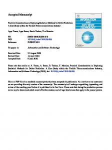
3(b)) to represent the accumulation of shear stresses on the slabs. Since typical linear structural analysis can only solve one unknown variable, the multiple unknown concentrated “line” loads cannot be determined simultaneously from the known free-field shear displacement. In Fig. 3, the soil shear stresses on vertical perimeter walls are not shown for clarity. With the seismic forces and appropriate load combinations defined by design codes and standards, structural members can be designed and detailed. Plastic hinges may be permitted for the performance level of “collapse prevention”. For the performance level of “repairable damage”, the hinges or the intended damage regions may be developed in beams or slabs rather than in walls. Repairing perimeter walls may require significant downtime, excavation and shoring work while repairing slabs is relatively practical. The free-field deformation method may encounter some difficulties in designing station structures. Firstly, this method is overly conservative for stiff structures. Secondly, this method may require deformation joints when the imposed shear deformation causes plastic rotation of joints (Kuesel 1969). The deformation joints subsequently cause technical issues for both the structural and envelope design. Alternatively, Wang (1993) suggested pinned connections at walls/slabs joints to increase the flexibility of the structure. Thirdly, the assumed soil pressure patterns are totally based on engineering judgment, the accuracy of which significantly affects the results of structural design. For complex structures with steps, slopes or irregular shape, the soil pressure patterns are difficult to justify. 3.2 Dynamic earth pressure methods Dynamic earth pressure methods include the Mononobe-Okabe method (Mononobe and Matsuo 1929, Okabe 1926), the Wood Method (Wood 1973) and other similar methods developed for earth retaining walls. The Mononobe-Okabe method assumes that the walls are free to move sufficiently so that a yielding active earth wedge can form behind the wall. This method is believed to be suitable for underground structures with a “U” shape or shallow burial depth. The Wood method assumes rigid walls and rigid foundations, which yields a dynamic thrust approximately 1.5 to 2.0 times of that from the Mononobe-Okabe method. The Wood method may apply to station structures with end walls which act as rigid diaphragms to prevent the structures from rotation (Wang 1993). The recent study by Atik and Sitar (2010) indicates that the Mononobe-Okabe method may significantly overestimate the soil pressure for cantilever retaining structures. 3.3 Design for rocking mechanism Fig. 4(a) shows a very rigid section with an end perimeter wall. Depending on soil conditions, seismic intensity, structural configuration and density, this section may rock or rotate as a giant rigid body, rather than structural distortion. Therefore, the rocking section as a whole rotates to accommodate the shear deformation from the soil. Seismic forces applied to this section of the structure can be equivalent to that of a giant “retaining wall” (Fig. 4(b)). This giant “retaining wall” has lateral support from the passive side. The rocking mechanism requires related structural members and components to be designed for the redistribution of gravity loads as well as seismic loads. In cohesionless soils, station structures with a low density may be lifted by the rocking mechanism under reversed cyclic loads. This type of rocking mechanism may be suitable for structures with a shallow burial depth, deep excavated depth and narrow horizontal width.
Some practical considerations in designing underground station structures for seismic loads
497
Fig. 4 A rigid section with rocking mechanism (end perimeter wall)
Fig. 5 A flexible section with rocking mechanism (interior section)
Properly detailed frames consisting of walls, slabs and columns can also develop a rocking mechanism locally with plastic hinges, as shown in Fig. 5. It is desirable to develop plastic hinges in the slabs and beams rather than in the walls, as the failure of perimeter walls may cause progressive collapse. If interior walls and columns cannot be designed to be stronger than beams and slabs according to the capacity design principle (Paulay and Priestley 1992), they can be detailed for plastic hinges with a sufficient rotational ductility. Repairing slabs and beams after earthquakes requires less downtime and excavation work than repairing perimeters walls. For large-span roof structures, slab bands supported by columns and walls can be used to decrease the slab thickness near plastic hinges, which therefore reduce the thickness of walls and columns. To develop the rocking mechanism, the edge portions of roof slabs, middle slabs and base slabs have to work together with the perimeter walls as a whole system. The gravity loads are sustained by the friction from the surrounding soil and the bearing resistance from the bottom. Plastic hinges are expected to experience large strain with concrete spalling. The design and detailing of plastic hinges may follow the requirements for ductile moment frames in appropriate design standards, such as ACI-318 (2008). The shear reinforcement at plastic hinges typically
498
Jianzhong Gu
requires closed hooks or 135° hooks on both ends, which is difficult to place for slab construction. The stirrups used in some conventional slab construction have a 135° hook on one end and a 90° hook on the other end to facilitate the construction. Seismic performance of such conventional slab shear reinforcement in plastic hinges is to be studied further. If the slabs are thick enough, “U” shape shear reinforcing bars may be a better solution, as they can be inserted from the top and bottom of the slab alternatively. The design of rock mechanism can be implemented by transferring gravity loads through a tilted rigid body. This mechanism need sufficient soil bearing pressure to support eccentrically loaded components from gravity loads. The design procedure is the same with the foundation design under earthquake loadings. The rocking mechanism relies on stiff configurations, including rigid perimeter walls, interior walls and strong connections. Stiff configurations permit station designers to thicken and/or over-reinforce structural members for “collapse prevention” during unexpected seismic events. In above-ground structures, the rocking mechanism is to develop energy dissipation between the foundation and the soil. The rocking mechanism in underground structures allows the structures to develop shear or racking deformation in order to accommodate soil shear distortion. Structures with rocking mechanisms do not expect significant seismic forces for shear waves, except in some localized regions. Although the rocking structures can be analogue to tilted retaining walls to a certain degree, they do not have to be designed for sliding or overturning. The seismic forces on the rocking structures are expected to be lower than retaining walls in a similar situation, as they have lateral supports from the passive side. Therefore, some simple earth pressure method may be used to account for the effect of other types of earthquake waves. To achieve the rocking mechanism, the soil bearing capacity can be designed at the ultimate condition. The capacity design principle may be employed in designing structural members and plastic hinges in high seismic regions. Structures with rocking mechanisms can accommodate large shear deformation from the surrounding soil, which is suitable for severe hazard levels, such as the maximum considered earthquake. The nature of rocking mechanisms is a simplified soil-structure interaction analysis that considers structural macro movement and internal load redistribution. The design of structures with rocking mechanisms requires collaborated efforts between the structural engineer and geotechnical engineer. The design method using rocking mechanisms can be a reliable and robust method for station structures with complex configurations.
4. Conclusions Underground structures require shear or racking deformation capacity to accommodate the movement of the surrounding medium, rather than designated energy dissipation systems that are commonly used for above-ground structures. The design of station structures demands the consideration of structural robustness under extreme events. Different design method may be used, depending on seismic hazards, site conditions, structural configurations and targeted performance levels. The free-field deformation method may be employed when the predicted free-field shear deformation is small enough to be tolerated by elastic structural deformation. For station structures with complex configurations, the assumed soil load pattern may be difficult to justify. This method may also require expensive displacement joints between rigid end sections and flexible interior
Some practical considerations in designing underground station structures for seismic loads
499
sections. A station structure can develop a rocking mechanism either as a whole rigid body or as a portion of the structure with plastic hinges. With the rocking mechanism, station structures can be tilted to accommodate lateral shear deformation from the surrounding soil. Plastic hinges may be developed in slabs and beams, rather than perimeter walls, in order to prevent progress collapse. Generally, rocking structures do not expect significant seismic loads from the soil, although the mechanism may result in significant internal forces and soil pressures. To address the effect of localized soil pressures and other types of earthquake waves, some empirical methods may be employed to determine design soil pressure. The underground station structures designed with rocking mechanism have rigid configurations, which has robustness for unexpected seismic events. This method offers engineers a relatively reliable design strategy for underground station structures.
References American Concrete Institute (ACI) (2008), Building Code Requirements for Structural Concrete, ACI 31808, Farmington Hills, MI. Anastasopoulos, I., Gerolymos, N., Drosos, V., Kourkoulis, R., Georgarakos, T. and Gazetas, G. (2007), “Nonlinear response of deep immersed tunnel to strong seismic shaking”, J. Geotech. Geoenviron. Eng., 133(9), 1067-1090. Atik, L. and Sitar, N. (2010), “Seismic earth pressures on cantilever retaining structures”, J. Geotech. Geoenviron. Eng., 136(10), 324-1333 Bobet, A., Fernandez, G., Huo, H. and Ramirez, J. (2008), “A practical iterative procedure to estimate seismic-induced deformations of shallow rectangular structures”, Can. Geotech. J., 45, 923-938. Cough, R.W. and Penzien, J. (1993), Dynamics of Structures, 2nd Edition, McGraw-Hill, Inc. Singapore. Hashash, Y.M.A., Hook, J.J., Schmidt, B. and Yao, J.I. (2001), “Seismic design and analysis of underground structures”, Tunnel. Under. Space Tech., 16, 247-293. Hung, C.J., Monsees, J., Munfah, N. and Wisniewski, J. (2009), Technical manual for design and construction of road tunnels-civil elements, Report No. FHWA-NHI-10-034, U.S. Department of Transportation, Federal Highway Administration, Washington, D.C. Huo, H., Bobet, A., Fernandez, G. and Ramırez, J. (2005), “Load transfer mechanisms between underground structure and surrounding ground: evaluation of the failure of the Daikai Station”, J. Geotech. Geoenviron. Eng., 131, 1522-1533. Kontoe, S., Zdravkovic, L., Potts, D.M. and Menkiti, C.O. (2008), “Case study on seismic tunnel response”, Can. Geotech. J., 45, 1743-1764. Kuesel, T.R. (1969), “Earthquake design criteria for subways”, J. Struct. Div., ASCE, 95(ST6), 1213-1231. Mononobe, N. and Matsuo, M. (1929), “On the determination of earth pressures during earthquakes”, Proceedings of the World Engineering Congress, 1. Monsees, J.E. and Merritt, J.L. (1991), “Earthquake considerations in design of the Los Angeles Metro”, Proceedings of the 3rd U.S. Conference on Lifeline Earthquake Engineering, ASCE, Los Angeles, CA. Okabe, S. (1926), “General theory of earth pressure”, J. Jpn. Soc. Civil Eng., 12(1). Paulay, T. and Priestley, M.J.N. (1992), Seismic Design of Reinforced Concrete and Masonry Buildings, John Wiley & Sons, Inc. Penzien, J. (2000), “Seismically induced racking of tunnel linings”, Earthq. Eng. Struct. Dyn., 29, 683-691. Penzien, J. and Wu, C.L. (1998), “Stresses in linings of bored tunnels”, Earthq. Eng. Struct. Dyn., 27, 283300. Samata, S., Ohuchi, H. and Matsuda, T. (1997), “A study of the damage of subway structures during the 1995 Hanshin-Awaji earthquake”, Cement Concrete Compos., 19, 223-239.
500
Jianzhong Gu
St. John, C.M. and Zahrah, T.F. (1987), “Aseismic design of underground structures”, Tunnel. Under. Space Tech., 2(2), 165-197. Wang, C.J. (2011), “Seismic racking of a dual-wall subway station box embedded in soft soil strata”, Tunnel. Under. Space Tech., 26, 83-91. Wang, J.N. (1993), Seismic Design of Tunnels, Parsons Brinckerhoff Inc, New York, NY. Wood, J.H. (1973), “Earthquake-induced soil pressures on structures”, Doctoral Dissertation, Calif. Institute of Tech., Pasadena, CA. Wu, C.L., Ostadan, F., Tseng, W.S. and Chai, J. (2008), “Cut-and-cover structures: seismic response and design”, Proceedings of the Geotech. Earthquake Eng. and Soil Dyn. IV Congress, ASCE, GSP 181. Yamato, T., Umehara, T., Aoki, H., Nakamura, S., Ezaki, J. and Suetomi, I. (1996), “Damage to Daikai subway station, Kobe Rapid Transit System and estimation of its reason”, Proceedings of the Technical Conf. on the Great Hanshin-Awaji Earthquake, Japan Society of Civil Engineers, 1, 247-254.
CC