Proceedings of the 35th Hawaii International Conference on System Sciences - 2002
Source Code Generator Based on a Proprietary Specification Language Krešimir Fertalj, Damir Kalpić, Vedran Mornar University of Zagreb Faculty of Electrical Engineering and Computing Unska 3, 10000 Zagreb, Croatia
[email protected],
[email protected],
[email protected] Abstract An application generator has resulted from the authors' efforts to improve the development of interactive database applications. The developed tool is based on a meta-base. The meta-base comprises an extended data model, the programming language description and some additional information to support the generation process. The procedures described in a proprietary specification language serve to generate the application over the database modeled in the meta-base. The specification language is based on the source code templates, standard program structures and on special statements for handling of the meta-data. Main ideas and operating principles of the original application generator are exposed. The specification language, its syntax and its basic components are described. The generator functionality is explained on some simple specification examples where the SQL code and pseudo-code for the corresponding hypothetical application are generated. Some experience gathered from the generator practical usage is discussed. A list of projects is included, where some complex applications were developed by the aid of the generator. An analysis is presented to show the proportions of the generated source code versus manually written statements.
1. Introduction The idea to develop an own source code generator crossed our minds about a decade ago. At that time, there were only a few of such tools at the market. They were not of a significant help, or they were part of the development system that we were not using (e.g. dBase/Clipper, Clarion). Other products, which appeared on the market after we had developed the pilot version of our tool, were not significantly better than our tool. We found that some of them generated only a few components of an application (e.g. database schema, screen forms) and that most of them did not preserve manually written code in
case of a repeated generation. We needed a tool that would be capable of repeated generation of a "complete" application in a single pass, where the application should consist of what we call standard modules [7]. Every module is aimed to handle the data in a single database table but it can also interact with other generated modules. Furthermore, we required a tool that we can use for different languages and DBMSs (namely ZIM, Informix and Visual Basic) and for different types of applications (stand alone, server, client-server). Finally, we wanted to have a tool, which would generate the source code that looked like as if we had written it by ourselves. Due to all that, we considered the applicability of other tools as significantly low for us, so we continued the development and usage of our tool. The generator of database applications described in this paper has been developed following the requirements that stem from the method described in [7]. The generator is built over the meta-base, which comprises an extended data model, the programming language description and some additional information to support the generation process. It is assumed that the data model must be brought into the third normal form [3] [4]. The data modeling is done with help of the tool, which is capable to check the data model and to generate the meta-data. The specification language is defined, which enables the generation of complete applications in source code, based on source code templates. The manually coded parts are preserved by an originally devised procedure that compares the files produced in subsequent steps of generation to the manually changed files. The procedure relies on the algorithms for file comparison described in [11] [12] [16] [17]. Description of the algorithms upon which the procedure is based, would exceed the scope of this paper. The rest of the paper is organized as follows. Section 2 briefly describes the main ideas and operating principles of the tool. Section 3 describes the meta-base. In section 4, the specification language is described. The generator functionality is explained on some simple examples in section 5. Some experience gathered from the generator practical usage is discussed in section 6.
0-7695-1435-9/02 $17.00 (c) 2002 IEEE
Proceedings of the 35th Annual Hawaii International Conference on System Sciences (HICSS-35’02) 0-7695-1435-9/02 $17.00 © 2002 IEEE
1
Proceedings of the 35th Hawaii International Conference on System Sciences - 2002
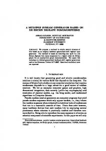
2. The main ideas and operating principles The main ideas and operating principles of the generator are depicted by the following figures. The tool is capable to generate database schema, application programs and user interface, based on the data model and on the definition of the programming language that are stored in the meta-base (Figure 1). The control statements drive the generation process. Besides that, some meta-data can be generated and automatically stored into the metabase. For instance, relationships between entities are generated based on primary keys and candidate foreign attributes, and forms are generated based on the data model definitions and predefined form generation parameters. Description of target language
APPLICATION Database
Data model
GENERATOR
Programs User interface
Control statements
Figure 1. The main ideas Figure 2. presents the main processes carried out while working with the generator.
MOD
SRC
1
system description analysis
4
data model analysis
specification analysis
META-BASE 3
5
meta-data generation
p-code generation 6
CTL
3. The meta-base 3.1. The basic meta-model
SYS
2
1. The system analyzer analyzes the programming language and DBMS description stored in text files (SYS) and stores the corresponding data into the meta-base. 2. The data model analyzer processes the data model (MOD) described in the proprietary input language, normalizes the descriptions being processed and stores them into the meta-base. 3. Meta-data generator generates relationships and screen forms by inspecting the meta-base contents and stores the generated objects into the meta-base. 4. The language analyzer analyzes the source code of the specifications (SRC) that were previously written for the chosen programming language. 5. Intermediate code (p-code) generator generates the p-code of processed specifications. Depending on the control parameters, the p-code can be stored too for further execution (TEM) and can be used by pcode interpreter. 6. The language analyzer processes the control statements and invokes the p-code interpreter, which generates the application. After the generation is completed, the database can be created in DBMS by execution of the generated statements that are written in correspondent data definition language. In addition, the generated source programs must be compiled. This can be activated manually or it can be automated by use of appropriate utilities.
application generation
TEM
APPLICATION
Figure 2. The operating principles
The model of the database, for which an application is generated, is stored in part of the meta-base shown in Figure 3. The meta-model comprises the objects described in relational and post-relational database theory [2] [15]. The information about the entities is stored in the metatable Entity. Short name of an entity (ShortName) can be used in combination with some affixes to form the names of program variables and names of other objects, such as screen forms and source files. The long name (LongName) can be used to form the headings of screen forms, reports and menus to be generated. The attributes associated with each database entity are called fields (Field). Field is described by properties that define required data values, creation of an index over that field, auto increments and persistency of the field data. All entity fields are defined over the attributes that are stored in one set (Attribute). Long name of an attribute can be used to generate the labels for fields defined over that attribute. The attributes are defined over domains (Domain), which define data type, data entry and data display properties of attributes (i.e. fields) that are defined over a domain. Entity key is defined by a set of entity fields (KeyField). Keys can be simple or composite. Several candidate keys can be
0-7695-1435-9/02 $17.00 (c) 2002 IEEE
Proceedings of the 35th Annual Hawaii International Conference on System Sciences (HICSS-35’02) 0-7695-1435-9/02 $17.00 © 2002 IEEE
2
Proceedings of the 35th Hawaii International Conference on System Sciences - 2002
defined for an entity. A key with minimal key number (SN) is regarded as the entity primary key, while the others are alternate keys. Definition of a key comprises a KeyName, which is used as the name of a primary key constraint or an index created over the key. The information about the relationships between the entities is stored in meta-table Relationship. The binary and unary relationships of type one-to-many can be defined. The entity referenced by the foreign key is called Parent entity (ParentName) and entity that references the parent entity by its foreign key is called Child entity (ChildName). The primary-foreign attribute pairs that define a relationship are described in Relationship Field (ParFldName, ChiFldName). For each relationship, an alias for parent table can be defined (ParentAlias) in order to resolve ambiguity in perception of referenced table Domain DomName TypeName DomLen DomDec Case Just DataMask ValRule
Attribute AttName LongName
Entity EntName ShortName LongName
Field Required Index Serial Virtual SN
when dealing with parallel and unary relationships. Referential integrity constraints [4] can be defined at the level of relationship (InsRule, DelRule), specifying the actions to be performed when inserting a Child or deleting a Parent (none, restrict, cascade, set null, set default). Referent Field defines the Parent attributes (RefFldName) to be shown on the screen forms and reports of a Child. As for the parent aliases, the aliases can be given for such fields (DomFldName). Screen forms (Form) and their fields (Form Field) are generated based on the data model, thus they can be regarded as dynamical enhancements of the model. The information about the source entity and entity fields is stored in Form and Form Field respectively. A form field is defined by position and size of a label and a variable part of the field. Form FormName EntName FormWdth FormHght Referent Field RefFldName DomFldName SN Relationship RelName ShortName ParentAlias InsRule DelRule
Key KeyNo KeyName
Key Field SN
Relationship Field ParFldName ChiFldName SN
Form Field FormName FFldName SN FormFldId VarRow VarCol VarWdth VarHght Label LabRow LabCol LabWdth LabHght
Figure 3. The basic meta-model Form Definition SysCode FDefName FDefDesc MaxRows MaxCols RowSp ColSp GenVars GenLabs ShortForm GenRefs DetailForm Compress JustVars VarLabs ScrollFlds BoxFlds Prefix Suffix VarStart VarEnd
System Parameter
Param ParCode ParDesc
ParValue
System SysCode SysName
Specification Argument ArgId ArgType
Specification SpecId SpecDesc SpecFile
Control ArgVal
DataType TypeName MinLen MaxLen LenReq DefLen DecReq DefDec
Project ProjName LongName ProjDir
Control Script ScrCode ScrDesc
Figure 4. The DBMS description and information to support the generation process
0-7695-1435-9/02 $17.00 (c) 2002 IEEE
Proceedings of the 35th Annual Hawaii International Conference on System Sciences (HICSS-35’02) 0-7695-1435-9/02 $17.00 © 2002 IEEE
3
Proceedings of the 35th Hawaii International Conference on System Sciences - 2002
3.2. The programming language description The programming language and DBMS description and some additional information to support the generation process are also stored in the meta-base (Figure 4). For each DBMS, the data types are described (DataType). The user of the tool can define some other parameters (System Parameter) to describe the system. Those parameters can be accessed from the specification language in order to maneuver the generation process. The Form Definition stores the parameters required to generate the screen forms, such as form size (MaxRows, MaxCols), form field spacing (RowSp, ColSp), form field components (GenVars, GenLabs) and layout parameters (Compress, JustVars, VarLabs, ShortForm, DetailForm). The rest of the meta-base stores the information about the specifications (Specification, Specification Argument) and scripts to control the generation process (Control Script, Control). A set of specifications must be written once for chosen DBMS and programming language and can be reused many times. For example, we used the same specifications to generate the applications in different projects realized within the same release of particular 4GL/DBMS, but control scripts that were specific for particular project were driving the generation process.
4. The specification language The specification language comprises statements for writing specifications, statements for describing the DBMS, data definition statements, and control statements for managing the generation process. The language analyzer is implemented as a recursive-descent parser of context-free grammar [1] [9] [21]. A short-form of the language syntax is described by rewriting rules (productions) in BNF (Backus-Naur Form) notation [1] [20]. Only those parts of the language that are relevant for understanding of this article are presented here. The language treats the following as tokens: constants, identifiers, operators, keywords and punctuation symbols. Additionally, the language recognizes source code template and macro variable. The expressions can be composed of combinations of operators (arithmetic, relational and string operators), constants, variables (user defined and system variables) and built-in functions (e.g. string manipulation functions and formatting functions).
Syntax:
::=
::=
::= ::=
The statements fall into following categories: • Structural statements. SPEC and ENDSPEC define the beginning and the end of a specification. • Declaration statements. GLOBAL declares global variables and DECLARE declares local variables. The variables can be defined by basic data types (INT, LONG, FLOAT, CHAR) or they can be defined as records with structures from the metabase objects. For example, the declaration DECLARE rEnt LIKE Ent declares the record rEnt with structure of tuple Ent. • The assignment statement LET. • Sequence-control statements. For example, IFELSE-ENDIF, WHILE-ENDWHILE, BREAK, NEXT (synonym CONTINUE), CALL and EXIT. • Output statements. For example, OUTPUT redirects the output during the specification execution, PRINT prints any regular expression to current output, and SCREEN prints a formatted screen form. • Special statements to handle the meta-data, as we shall describe later in this chapter.
4.2. Source code templates The difference between the statements and the code templates is that statements are executed, while templates are decomposed to text parts and macro variables that are written to output after the macros have been substituted by corresponding values. The template text can consist of any character, except the EOF (end of file) character. Special characters can be used within texts to generate the graphical user interface. Only identifiers can be used as macro variables. Syntax:
4.1. Specifications and statements
Specification is a program or a subroutine, which is composed of a declaration part and a specification block. No special syntactic structure is defined to represent the main program. A specification that is interpreted first is treated as the “main” specification. The specification block consists of source code templates and statements.
::= > | ε ::= {} ::= | ::= {} | ε ::= #< > | ε
4.3. Statements to handle the meta-data The FOREACH statement collects the meta-data and dynamically creates a named set of records from
0-7695-1435-9/02 $17.00 (c) 2002 IEEE
Proceedings of the 35th Annual Hawaii International Conference on System Sciences (HICSS-35’02) 0-7695-1435-9/02 $17.00 © 2002 IEEE
{} {} SPEC ENDSPEC {} | |ε
4
Proceedings of the 35th Hawaii International Conference on System Sciences - 2002
the meta-table . The optional WHERE clause specifies the records to be collected.
manipulation statements, the SYSSTAT variable is set to the count of processed records.
Syntax:
Syntax:
::=
::=
FOREACH -> ENDFOREACH WHERE | ε
After the set is formed, the built-in variable SYSSTAT is set to the number of collected records and the statement starts to perform a loop, executing for each record in the set. Built-in functions CURRPOS () and LASTPOS () can be used inside the loop to determine the absolute position of the current record in the set and the count of records in the set. The statement FETCH selects a record from the metabase and fills the specified variable with that record. If more than one record can be selected, the first record is taken. Syntax:
::= FETCH ::= INTO | ε
COUNT counts the meta-records and puts the result into the specified variable. As for the other meta-data
::= COUNT
The following statement generates a screen form for an entity, based on the form definition previously stored in the meta-base (Form Definition on Figure 4). Optionally, the name for the resulting form can be specified, as well as the name of parent entity for the master-detail form. Syntax:
::= GENFORM
5. The application generation The generator functionality is explained on specification examples where the code for a hypothetical application is generated. The data model of the application is shown in Figure 5. Person can be born in one City and currently can live in another City. This is a good example of two parallel relationships (BornIn, LivesIn) defined by complex foreign keys (CountryCode + CityCode). Obviously, parent aliases should be given to City in order to distinguish its roles (CityOfBirth, CityOfLiving). CountryCode = CountryOfBirthCode CityCode = CityOfBirthCode
Person PersonId Surname Name CountryOfBirthCode CityOfBirthCode CountryOfLivingCode CityOfLivingCode Street
CHAR(13) CHAR(25) CHAR(25) CHAR(2) INTEGER CHAR(2) INTEGER CHAR(30)
BornInCity
CityOfBirth
CountryCode CityCode CityName
City CHAR(2) INTEGER CHAR(40)
LivesInCity
CityOfLiving CountryCode = CountryOfLivingCode CityCode = CityOfLivingCode
Figure 5. The data model of a hypothetical application
5.1. Database generation The following specification generates the SQL statement that creates a database table. In practice, the SQL statements for creation and dropping of complete database, as well as the statements to transfer the data via text files, are generated in the same way. This example shows how to generate the statements for creating the tables together with primary keys. Example: Specification of SQL to create table SPEC CreateTable ... > Print sEnt.EntName
ForEach Fld Where Fld.EntName=sEnt.EntName -> sFld > Print sFld.Fldname, " "; Call PrintDataTypeAndNULL (sFld) EndForEach /* sFld */ ForEach Key Where EntName=sEnt.EntName -> sKey If CurrPos(sKey) > 1 EndIf If CurrPos(sKey) = 1 > Else > EndIf
0-7695-1435-9/02 $17.00 (c) 2002 IEEE
Proceedings of the 35th Annual Hawaii International Conference on System Sciences (HICSS-35’02) 0-7695-1435-9/02 $17.00 © 2002 IEEE
5
Proceedings of the 35th Hawaii International Conference on System Sciences - 2002
REFERENCES >> Print sRel.parentname, " ("; ForEach KeyFld Where EntName=sKey.EntName And KeyNo=sKey.KeyNo -> sKeyFld If CurrPos(sKeyFld) > 1 EndIf Print sKeyFld.FldName; EndForEach Print sKey.keyname;
CALL PrintReferencedFlds (sRel) If sRel.DelRule = "D" > EndIf
EndForEach /* sKey */ > Print sRel.RelName >> EndForEach /* sRel */ ENDSPEC /* RefInt */
> ENDSPEC /* CreateTable */
In practice, for each entity a statement that creates the corresponding table is generated (CREATE TABLE). For each entity field, the field name, field type, field width, and number of decimal places are specified. The NOT NULL is generated for primary attributes and attributes having Required flag set (see Figure 3). The PRIMARY KEY constraint is set for the first key and UNIQUE...CONSTRAINT is set for alternate keys. The following example shows the SQL script generated for the Person shown in Figure 5.
Print sRel.ChildName; >
The specification PseudoInput generates pseudo-code of a nonprocedural statement for editing of the data by using a screen form. In practice, the user is provided with information about the function that is to be performed (adding of a new record or update of the record currently displayed on the screen). Update of the primary key is not allowed and primary fields are disabled when editing for update takes place. After that, the nonprocedural statement to handle the form input is invoked. Finally, depending on user action, the form is refreshed with the data that were displayed before editing, or the edited record is stored into the database. Example: Specification of code to handle the input of data from the screen form SPEC PseudoInput vEntName Char(18) ... > ForEach Rel Where ChildName=vEntName -> sRel Let vParent = sRel.ParentName Let vAlias = sRel.ParentAlias
CALL PrintForeignKeyFlds (sRel)
Let vForFld = "" Let vForKey = "" Call CalcForeignFieldLists(sRel, vForFld, vForKey)
EndForEach /* sRel */
in field CountryOfBirthCode,CityOfBirthCode if KeyPressed (LASTKEY, {chaining keys}) HandleCity (LASTKEY, rPerson.CountryOfBirthCode, rPerson.CityOfBirthCode) # reference & chain City as CityOfLiving ... /* the code as for the CityOfBirth */ end input in rPerson
5.4. Generation of user interface
> ENDSPEC /* PseudoInput */
Integrity checks are performed within the form input, as shown in the next example. If a user tries to omit the primary key, a message about the required values for key fields is issued and the user is forced to enter the primary key. When the primary key is set, a check is made and the user is warned if attempting to enter duplicate identifiers (see after field PersonId). In the same way the referential integrity checks are performed (e.g. after field CountryOfBirthCode, CityOfBirthCode). Furthermore, this example illustrates how to generate the statements for procedure chains [7]. If in the field that represents a foreign attribute (e.g. in field CountryOfBirthCode, CityOfBirthCode) one of the keys for procedure chains is pressed, a function to handle the referenced table is called (e.g. HandleCity). This function allows the user to perform the data entry of the record that is going to be referenced, and to return a new value of the foreign key for which the function was called. The generation of the source code for concrete 4GLs is described in [6]. Example: Generated pseudo-code form input into record rPerson # entity integrity after field PersonId if (rPerson.PersonId) is null Message ("Value required") if PersonExists (rPerson.PersonId) Message ("Person already exists") # reference & chain City as CityOfBirth after field CountryOfBirthCode,CityOfBirthCode if (rPerson.CountryOfBirthCode, rPerson.CityOfBirthCode) is not null SelectCity (rPerson.CountryOfBirthCode, rPerson.CityOfBirthCode) if (rPerson.CountryOfBirthCode, rPerson.CityOfBirthCode) is null Message ("Not existing CityOfBirth")
User interface is generated in the following way. Metadata that define screen forms (Form and Form Field in Figure 3) are generated by GENFORM statement as described in section 3. After the meta-data for a screen form are generated, the source code for that form can be generated in the same way as the SQL code and program code are generated.
6. Practical experience Practical use has shown that our tool is capable of generating the modules with basic functions for handling of data [7]. The tool was used internally to make projects for external customers. Several projects were accomplished in this way: • The program to support the employment office management (EOM), • Information system for production planning of automobile parts (ISPAP) [13], • Information system for student administration (ISSA) [14], • Information system for technical maintenance (ISTM) [10], • Application to handle the register of scientists (ROS), • The program to support the selling of encyclopedia editions (SEE) • IS for HR Management in the Ministry of Defense of Croatia (ISHR) [8]. The projects were realized in various releases of the DBMSs Informix and ZIM. Table 1 shows the size of the projects and the share of generated code within the whole product. The rightmost column presents the share of the coding time within the project time. For some cases, (ISPAP, SEE and ISHR) the source code was delivered to the customer, so that the percentage does not include the time possibly consumed later by the customer alone.
0-7695-1435-9/02 $17.00 (c) 2002 IEEE
Proceedings of the 35th Annual Hawaii International Conference on System Sciences (HICSS-35’02) 0-7695-1435-9/02 $17.00 © 2002 IEEE
7
Proceedings of the 35th Hawaii International Conference on System Sciences - 2002
Table 1. Analysis of proportions of the generated versus manually coded statements Project DBMS Entities Relationships Generated Manually coded EOM Zim 56 27 75% sophisticated functions ISPAP* Zim 106 310 55% sophisticated functions ISSA** Informix 78 90 20% sophisticated functions ISTM** Informix 85 116 10% sophisticated functions ROS Informix 39 44 90% sophisticated reports SEE Zim 47 83 80% sophisticated functions ISHR** Informix 131 228 40% sophisticated functions * The generated system was connected to a linear programming system [13]. ** Estimated values for the first three years of the project. The share of generated code is estimated based on the data model size, the subjective estimation of the complexity of the manually coded elements and by the comparison of the generated and the final files. The share of coding was calculated based on the known number of working hours. Depending on the project, between 10% and 90% of the source code was generated. The best results were achieved when the code had to handle straightforward data processing. The size of the model did not matter. The share of the generated code was decreased relative to the number of embedded sophisticated functions. This is natural, because such functions must be programmed manually. In projects like ISSA or ISTM, a significant amount of code was generated and fast initial results were achieved, although the final share of the generated code is low and the coding took a longer time. The percentage of the coding phase within the project is about 60%. This percentage seems to be big. One of the reasons is an early start of the implementation. In this way, early phases where shortened and a part of the design was done during implementation. The prototyping and frequent interaction with users had additionally increased the coding time. Generally, the software production rate was increased, but the overall time was not shortened significantly. The main benefit was in the quantity and quality of the software produced. For example, in ISHR project the initial database consisted of over 130 tables. For that database, 8.5 MB of source code (260 K lines in 570 files) was generated based on the specifications that took approximately 5 KB.
Coding 84% 31% 73% 64% 58% 71% N/A
program generated in a single pass has advantages over an ad hoc coded program, particularly for middle size databases. A generation process, based on correct specifications, ensures for the software its correctness (validity) and its conformity to the database scheme. The whole application obeys the same standards and appears homogenous to the users. Manual coding is impossible to avoid. Therefore, the main purpose of the generator is to produce only the basic functions to spare the programmers from the routine work. Instead, they can dedicate themselves to code the sophisticated functions. Their work is preserved by an original procedure that compares the generated and manually written code. Although specification language seems to be rather low level, specifications and specification scripts can be regarded as high-level concepts. Specifications combine the statements of the specification language with source code of the chosen programming language. Due to that, the code of specifications is sometimes hard to read. We believe that this problem is minimized by proper selection of keywords and by a good style of writing the specifications. The tool proved itself on real-world projects, which can be attested by the list of generated software. Still, some improvements should be done. In parallel to that, new technologies, such as XML and XSL, could be used to develop a completely new tool. We have done some efforts in that direction and some prototypes have already been created.
8. References
7. Conclusions The generation of application is performed by executable specifications written in the proprietary specification language. The specifications rely on the data model that is stored in a meta-base. In that way, the independence of the programming language and DBMS is achieved. The meta-base stores all information that is relevant for generation of complete applications in a single pass. A
[1] A.V. Aho and J.D. Ullman, Principles of Compiler Design, Addison-Wesley, Reading, MA, 1978. [2] P.P. Chen, “The Entity-Relationship Model - Toward a Unified View of Data”, ACM Transaction on Database Systems, Vol. 1, No. 1, 1976, pp. 9-36. [3] E.F. Codd, “Further normalization of the data base relational model”. In R. Rustin (Ed.), Data Base Systems, Prentice-Hall, Englewood Cliffs, New Jersey, 1972, pp. 3364. [4] C.J. Date, An Introduction to Database Systems, Sixth Edition, Addison-Wesley, Reading, MA, 1994.
0-7695-1435-9/02 $17.00 (c) 2002 IEEE
Proceedings of the 35th Annual Hawaii International Conference on System Sciences (HICSS-35’02) 0-7695-1435-9/02 $17.00 © 2002 IEEE
8
Proceedings of the 35th Hawaii International Conference on System Sciences - 2002
[5] A. van Deursen, P. Klint and J. Visser, “Domain-Specific Languages: An Annotated Bibliography”, ACM Sigplan Notices, Vol. 35, No. 6, 2000, pp. 26 -36. [6] K. Fertalj, An improvement of methods to accelerate and standardise the software application production, Ph.D. Thesis (in Croatian), ZPM FER, Zagreb, 1997. [7] K. Fertalj, D. Kalpic and V. Mornar, “A Software Development Method Based on Iterative Prototyping”, The World Multiconference on Systemics, Cybernetics and Informatics, July 31 - August 4, Orlando, 1999, Proceedings, International Institute of Informatics and Systemics, Orlando, FL 32837, USA, ISBN 980-07-5917-4, Vol. 2, 1999, pp. 83-90. [8] K. Fertalj, D. Kalpic, and N. Hadjina, "On-the-Scene Education of Information Technology Staff", Challenges of Information Technology Management in the 21st Century, IRMA International Conference, May 21-24, 2000, Anchorage, AK, USA, Idea Group Publishing, Hershey, USA, ISBN 1-878289-84-5, 2000, pp 942-943. [9] D. Grune and C.J.H. Jacobs, Parsing techniques – a practical guide, Ellis Horwood Limited, Chichester, West Sussex, England, 1990. [10] Z. Hebel, M. Baranovic and S. Zakosek, ISOHEP Computerised maintenance management system for Croatian National Electricity (HEP), Euromaintenance '98, Proceedings, Zagreb, HDO, 1998, pp. 233-240. [11] P. Heckel, “A Technique for isolating differences between files”, Comm. ACM, Vol. 21, No. 4, April 1978, pp. 264268.
[12] D. Hirschberg, “A Linear Space Algorithm for Computing Maximal Common Subsequences”, Comm. ACM, Vol. 18, No. 6, June 1975, pp. 341-343. [13] D. Kalpic, M. Baranovic and V. Mornar, “Case Study Based on a Multi-Period Multi-Criteria Production Planning Model”, European Journal of Operational Research 87, 1995, pp. 658-669. [14] D. Kalpic and V. Mornar, “Student Administration System”, European review conference proceedings "University-Enterprise Information Systems", Graz, September 15-16, 1994, pp. 124-131. [15] D. Maier, The Theory of Relational Databases, Computer Science Press, Rockville, Maryland, 1983. [16] W. Miller and E. Myers, “A File Comparison Program”, Software Practice and Experience, Vol. 15, No. 11, 1985, pp. 1025. [17] E.Myers, “An O(ND) Difference Algorithm and its Variations”, Algorithmica, Vol.1, No. 2, 1986, pp. 251256. [18] Proceedings of the 2nd Conference on Domain-Specific Languages DSL’99, ACM Sigplan Notices, Vol. 35, No. 1, 2000. [19] J.C. Ramming (Ed.), Proceedings of the Conference on Domain-Specific Languages DSL’97, USENIX Association, 1997. [20] E.J. Sammet, Programming Languages: History and Fundamentals, Prentice Hall, Englewood Cliffs, New Jersey, 1969. [21] A.T. Schreiner and H.G. Friedman, Introdution to Compiler construction with Unix, Prentice Hall, Englewood Cliffs, New Jersey, 1985.
0-7695-1435-9/02 $17.00 (c) 2002 IEEE
Proceedings of the 35th Annual Hawaii International Conference on System Sciences (HICSS-35’02) 0-7695-1435-9/02 $17.00 © 2002 IEEE
9