1, 2 and 5), two of C55/67 grade concrete (fc,cyl = 55 MPa) (No. 3 and. 4). Polypropylene 54 mm long synthetic fibers were used in three of the specimens.
MATEC Web of Conferences 6, 07005 (2013) DOI: 10.1051/matecconf/20130607005 � C Owned by the authors, published by EDP Sciences, 2013
Spalling of concrete subjected to blast loading M. Foglar1 and M. Kovar2 1 Assistant professor: Czech Technical University in Prague, Prague, Czech Republic 2 PhD student: Czech Technical University in Prague, Prague, Czech Republic
Abstract. This paper presents outcomes of the blast field tests of FRC and reinforced concrete specimens, which were performed in cooperation with the Czech Army corps and Police of the Czech Republic in the military training area Boletice. The numerical evaluation of the experiments focused on the spalling of concrete subjected to blast loading started after the first set of the tests, took almost 3 years and required further small-scale experiments performed in the labs of the Czech Technical University.
1. INTRODUCTION This paper presents outcomes of the blast field tests of FRC and reinforced concrete specimens which were performed in cooperation with the Czech Army corps and Police of the Czech Republic in the military training area Boletice. The test were performed using real scale reinforced concrete precast slabs with varying fiber content and concrete strength class and 25 kg of TNT charges placed in distance from the slab for better simulation of real in-situ conditions. The paper presents conclusions from two sets of experiments focused on the spalling of concrete subjected to blast loading and results of their numerical evaluation. The tests were performed in November 2010 and August 2011 at the military training area Boletice. The specimens were cast in Prague and had to be transported almost 200 km to the location of the tests. The numerical evaluation of the tests started after the first set of the tests, took almost 3 years and required further small-scale experiments performed in the labs of the Czech Technical University. The evaluation focuses on the extent of concrete spalling of specimens subjected to blast loading. 2. EXPERIMENTAL TESTING OF BLAST RESISTANCE OF FRC AND RC BRIDGES For further information about the experiments see [1]. 2.1 Specimens and materials The dimensions of the specimens were designed in real scale of a small span bridge as concrete slabs, 6 m long, 1.5 m wide and 0.3 m thick. Five specimens were made in total, where three of them were made of C30/37 grade concrete (fc,cyl = 30 MPa) (specimen No. 1, 2 and 5), two of C55/67 grade concrete (fc,cyl = 55 MPa) (No. 3 and 4). Polypropylene 54 mm long synthetic fibers were used in three of the specimens. The fiber dosage was following: specimen No. 1 0 kg/m3 , No. 2 4.5 kg/m3 , No. 3 0 kg/m3 , No. 4 4.5 kg/m3 and No. 5 9 kg/m3 . The dosage of the fibers was kept low as it can be achieved on-site. The specimens were designed to fulfill the design bridge loading according to EN 1991-2 design code. All specimens were reinforced by conventional reinforcement (B500B according This is an Open Access article distributed under the terms of the Creative Commons Attribution License 2.0, which permits unrestricted use, distribution, and reproduction in any medium, provided the original work is properly cited.
Article available at http://www.matec-conferences.org or http://dx.doi.org/10.1051/matecconf/20130607005
MATEC Web of Conferences
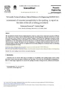
Figure 1. Layout of the experiment.
to EN 1992-1-1 design code, fyk = 500 MPa) at both surfaces, longitudinally by 11Ø16 mm reinforcing bars (every 140 mm), transversely by Ø10 mm (every 150 mm). The shear reinforcement was provided by Ø8 mm links (9 pcs/m2 ). 2.2 Layout of the experiments The experiments were carried out at the military training area Boletice in cooperation the Czech Army corps and Police of the Czech Republic. The blasts were performed on former artillery practice target area (900 m above sea level) which is now used for dismantling obsolete ammunition and ammunition from WW2 which is still found in the Czech Republic during construction works. The slabs were placed on timber posts which were fixed in position by steel tubes. The ground under the slabs was removed; 5 m in diameter and 1 m deep excavation was prepared under the slabs so the results of the experiments would not be influenced by rebound of the pressure wave. The 25 kg TNT charges were placed on steel “chairs” (3Ø10 mm links, 3 mm thick steel plate) in the middle of the slabs. The “chairs” provided off stand of 450 mm from the slab. This value was chosen as the most usual height of car trunk. The charges were covered by a woolen blanket. According to the cooperating pyrotechnic, the blanket would concentrate the blast wave by up to 15%. The woolen blanket represents the camouflage, as the charge would not be discovered by routine police road check when transported by car or the effect of backpack when transported on-foot. The charges were fired remotely by radio impulse. Layout of the experiments can be seen in Fig. 1. 2.3 Results of the experiments The experiments were focused on the effect of fibers, concrete compressive strength and its combination on blast performance of concrete. By means of performance it is understood the dimensions of puncture and spalling of concrete spalling. The differences in puncture and spalling of concrete on the soffit of the slabs can be found in Table 1. In this section, the findings presented in Table 1 are described in detail. The specimen No. 1, C30/37, no fibers, is regarded as the reference specimen. This specimen is the most damaged one by the blast loading. The area of the puncture is 0.43m2 , volume 0.12m3 , which represents 4.4% of the total volume of the specimen. Total volume of the damaged concrete (puncture + spalling) is 0.23m3 , which represents 8.5% of the total volume of the specimen. The sides of the specimen were damaged severely. The deflection was 295 mm on the left side and 310 mm on the
07005-p.2
IWCS 2013 Table 1. Comparison of blast performance of studied specimen.
Specimen No. Concrete Fibers Puncture – top surface Concrete spalling (soffit) - concrete cover Concrete spalling (top surface) - concrete cover Concrete spalling (left side) - concrete cover Concrete spalling (right side) - concrete cover Volume of crushed concrete Permanent deflection
1 C30/37 0.43 m2 2.35 m2
2 C30/37 4.5 kg/m3 0.26 m2 1.89 m2
3 C55/67 0.02 m2 1.51 m2
4 C55/67 4.5 kg/m3 0.73 m2
5 C30/37 9.0 kg/m3 0.61 m2
1.71 m2
1.09 m2
1.2 m2
0.44 m2
0.37 m2
0.43 m2
0.26 m2
0.89 m2
0.68 m2
0.66 m2
0.43 m2
0.26 m2
0.29 m2
0
0.08 m2
0.52 m2
0.05 m2
0.08 m2
0
0
0.35 m2
0
0.02 m2
0
0
0.34 m2
0.16 m2
0.08 m2
0
0
0.23 m2
0.11 m2
0.02 m2
0
0
0.23 m3
0.15 m3
0.20 m3
0.05 m3
0.06 m3
0.31 m
0.37 m
0.28 m
0.30 m
0.26 m
right side of the specimen. The shape of deflection was similar to deflection from uniformly distributed loading. The specimen No. 2, C30/37, 4.5 kg/m3 PP fibers was less damaged. The area of the puncture is 0.26m2 , volume 0.08m3 , which represents 2.9% of the total volume of the specimen. Total volume of the damaged concrete (puncture + spalling) is 0.15m3 , which represents 5.6% of the total volume of the specimen. The area of puncture was reduced by 40% in comparison to specimen No. 1, the total volume of damaged concrete was reduced by 35% in comparison to specimen No. 1. The left side of specimen No. 2 was not damaged, the damage of the right side was reduced by more than 50%. The deflection was 365 mm on the left side and 380 mm on the right side of the specimen. The shape of deflection was similar to deflection from point loading in the mid-span of the specimen. The deflection was increased by 19% in comparison to specimen No. 1. The specimen No. 5, C30/37, 9 kg/m3 PP fibers was less damaged. Total volume of the damaged concrete (puncture + spalling) is 0.06m3 , which represents 2.2% of the total volume of the specimen. There was no puncture, the total volume of damaged concrete was reduced by 75% in comparison to specimen No. 1. The sides of specimen No. 5 were not damaged. The deflection was 255 mm on the left side and 265 mm on the right side of the specimen. The shape of deflection was similar to deflection from point loading in the mid-span of the specimen. The deflection was decreased by 16% in comparison to specimen No. 1. The specimen No. 3, C55/67, no fibers was less damaged. The area of the puncture is 0.02m2 , volume 0.01m3 , which represents 0.4% of the total volume of the specimen. Total volume of the damaged
07005-p.3
MATEC Web of Conferences
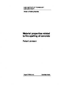
Figure 2. Damaged specimen No. 3 (RC) after blast – bottom view.
concrete (puncture + spalling) is 0.2m3 , which represents 7.4% of the total volume of the specimen. The area of puncture was reduced by 95% in comparison to specimen No. 1, the crushed concrete remained within the reinforcement matrix, total volume of damaged concrete was reduced by 15% in comparison to specimen No. 1. The damage to the sides was reduced by 85%. The deflection was 285 mm on the left side and 290 mm on the right side of the specimen. The shape of deflection was similar to deflection from uniformly distributed loading. The deflection was increased by 10% in comparison to specimen No. 1. The specimen No. 4, C55/67, 4.5 kg/m3 PP fibers was less damaged; its damage was similar to specimen No. 5. Total volume of the damaged concrete (puncture + spalling) is 0.05m3 , which represents 1.9% of the total volume of the specimen. There was no puncture, the total volume of damaged concrete was reduced by 22% in comparison to specimen No. 1. The sides of specimen No. 5 were not damaged. The deflection was 300 mm on the left side and 305 mm on the right side of the specimen. The shape of deflection was similar to deflection from point loading in the mid-span of the specimen. The deflection was increased by 15% in comparison to specimen No. 1. The extent of spalling decreased with increased fiber content. Specimen with high fiber content or medium fiber content and high compressive strength did not experience puncture. The concrete spalling at the sides of the specimens is caused by their small width – the blast overpressure wave passes around and causes surface tensile stresses. This spalling cannot occur at wider specimens, the slab behavior is dominant. The effect of blast loading on top and bottom surfaces of the specimens can be found in Figs. 2 to 3.
3. NUMERICAL EVALUATION The numerical evaluarion of the experiments is described in detail in [1]. A numerical model was successfully calibrated to describe the behavior of concrete slabs subjected to blast loading and the corresponding damage. The further research is focused on the detailed description of the behavior of the blast pressure wave propagation in the heterogeneous material and its behavior on the boundaries to other materials. This phenomenon is studied on specimens designed based on numerical investigations as prisms 300 × 300 × 120 mm. The specimens are loaded by a 0.05 kg TNT charge.
07005-p.4
IWCS 2013
Figure 3. Damaged specimen No. 5 (FRC) after blast – bottom view.
Figure 4. Compressive stress at the top surface of the specimen.
3.1 Description of the numerical model The LS-DYNA solver is used for non-linear analysis of fast dynamic phenomena like blast or impact. Within the calculation, the FEM mesh can adapt by deleting elements whose resistance was depleted; these FEM elements “erode”. The model composes of several parts. The air provides boundaries of the model; the explosive (e.g. TNT) transfers the energy from the blast to FE elements of the air, where the blast wave propagates. The concrete specimen is modeled by solids, for example of the set-up of the model. The air is modeled using the 009-Null material and forms the undeformable FE network. The concrete specimen is modeled by the 159- CSCM_Concrete material model (brittle material model with damage). The explosive is modeled by the 008-High explosive burn material model. The blast overpressure is calculated by the JWL equation of state (EOS): � � � � � �E � e−R1 V + B 1 − e−R2 V + · (1) p =A 1− R1 V R2 V V 07005-p.5
MATEC Web of Conferences
Figure 5. Propagation of the blast ovepressure wave in a concrete specimen.
Figure 6. Axial stresses at the soffit of the specimen by the time the blast overpressure wave reached its soffit – the brown color denotes eroded specimens.
The mesh size was chosen 10 mm for concrete and reinforcement and 20 mm for air. 3.2 Behavior of the blast pressure wave in the concrete; concrete spalling The blast pressure wave propagates from the spot of the incinerated charge. It reaches the top surface of the specimen and causes compressive stress in it. The value of the compressive stress is dependent on the distance of the charge from the surface of the concrete specimen and its mass. The value of the blast overpressure wave can be estimated based on empirical formulae, like e.g. the Hopkinson cube root law– Eq. (1). Z=
R 1
W3
·
Where R is the distance to the specimen in m and W is the weight of the charge in kg.
07005-p.6
(2)
IWCS 2013
Figure 7. Axial stresses at the soffit of the specimen by the time the blast overpressure wave reached its soffit – No eroded elements in numerical model.
The compressive stress at the top surface of the specimen can cause local crushing of concrete (Fig. 4) or a shear failure of the specimen (puncture by shear-punching behavior). The pressure wave propagates further by the speed of sound in the material. When the compressive stress wave reaches the soffit of the specimen, a part of it leaves in to the surrounding continuum while the rest rebounds back into the material. This rebound causes tensile stresses at the soffit of the material (as described in [2]). The concrete in the concrete cover is not able to cover these tensile stresses and spalls of the specimen (Fig. 6). The effect of added fibers was modeled according to the approach described in [1], the principle was adapted from [3]. Figure 7 shows the resulting tensile stresses at the soffit of the FRC specimen. 4. CONCLUSIONS The added fibers change the mechanism of the concrete spalling at the soffit of the specimen to more ductile which results into reduced volume of the spalled concrete. The debris was more concentrated by the fibers, it can be assumed, that it could not fly very far due its higher mass. The further research will be focused on the detailed description of the behavior of the blast pressure wave propagation in the heterogeneous materials.
ˇ This paper was supported by the Grant Agency of the Czech Republic Grant Projects No. GACR13-30441S and the CTU project No. SGS13/077/OHK1/1T.
References [1] Foglar M., Kovar M., Conclusions from experimental testing of blast resistance of FRC and RC bridge decks, International Journal of Impact Engineering, Volume 59, September 2013, Pages 18–28.
07005-p.7
MATEC Web of Conferences [2] S.G. Millard, T.C.K. Molyneaux, S.J. Barnett, X. Gao, Dynamic enhancement of blast-resistant ultra high performance fibre-reinforced concrete under flexural and shear loading, International Journal of Impact Engineering, Volume 37, Issue 4, April 2010, Pages 405–413. [3] A.M. Coughlin, E.S. Musselman, A.J. Schokker, D.G. Linzell,Behavior of portable fiber reinforced concrete vehicle barriers subject to blasts from contact charges, International Journal of Impact Engineering, Volume 37, Issue 5, May 2010, Pages 521–529.
07005-p.8