Spatial constraints in collaborative design processes A. Borrmann1, J. Hyvärinen2, E. Rank1 Computation in Engineering, Technische Universität München, Germany 2 Building Informatics, VTT – Technical Research Centre of Finnland
[email protected]
1
Abstract. User requirements, building codes, construction rules and regulations imply constraints on a building design. Additional constraints are introduced by the different participants of the collaborative planning process through the individual body of knowledge representing their particular domain. Checking digital building models for compliance with these constraints allows detecting design errors and conflicts in an early stage. To realize this, all constraints have to be represented in a computer-processable form. However, many regulations and codes make use of higher spatial concepts, such as “must contain”, “must be above”. Today, such constraints can only be implemented by software experts using advanced geometry algorithms. In order to facilitate the definition of spatial constraints for common users, the paper introduces the concept of providing predefined metric, directional and topological operators as ready-made building blocks. The paper discusses in detail a proposed extension of the IFC constraint framework to include these spatial operators and describes procedures for embedding spatial constraint checks in the collaborative planning process.
1 Introduction In most cases, products are made for fulfilling requirements. Buildings, for example, are erected for providing living, office or recreational space. At the same time, there are lots of other conditions that have to be satisfied by the product being designed and engineered, among them physical, economical, esthetical, and legal conditions. These requirements form constraints for the design and engineering process. In collaborative design processes, such as the planning of buildings, the individual participants of the diverse domains involved typically have those constraints in mind which represent the body of knowledge of their particular design or engineering domain. A project’s structural engineer, for example, may demand a certain slab thickness while at the same time the architect requires a minimum clear height in the building’s rooms. Formalizing such constraints in a way they become interpretable by computers allows to •
detect constraint violation and
•
detect conflicts between contradictory constraints
during the design phase, improving the design coordination and thus helping to reduce costs and prevent time delays. A necessary precondition for processing constraints is a computer interpretable representation of the product being designed. In the case of AEC design processes, building product models, also known as building information models (BIM), form such a suitable representation. These models capture not only the three-dimensional geometry of the building, but also the semantics of the individual elements by applying object-oriented modelling concepts (Eastman et al., 2008). The most mature and wide-spread standardized building product model is called Industry Foundation Classes (IFC)1, developed and maintained by the buildingSmart consortium2. Combining digital building models with a formalized rule basis representing 1 2
http://www.iai-tech.org/products/ifc_specification http://www. buildingsmart.com
1
requirements or building codes opens the way for an automated check of compliance of a building design. However, the major challenge lies in the process of formalizing these codes and requirements. From an information processing point of view, current building codes and regulations are written in a rather informal way, using semi-legalistic jargon. This is due to the fact that these documents are meant to be interpreted by humans and not by machines. Though such informal specifications are often ambiguous, inconsistent and contradictory, humans are able to follow them, thanks to their experience, context-awareness, and “improvisations” capabilities. However, a direct implementation of the original regulation texts in a form processable by computers is, in most cases, impossible. Instead, a laborious manual translation is required which involves a lot of interpretation. This process has been realized in many different code checking projects (Liebich et al., 2002; Ding et al., 2006, Eastman, 2009). Due to the inherent spatial nature of the subject, many clauses in building regulations imply constraints with spatial semantics. A typical example is a clause in the German Landesbauordnungen that requires a heat and smoke vent to be located directly above the exit staircase. Today, such requirements can be included in a rule base only by experts with advanced knowledge on the geometry representation in building models and access to advanced geometry processing systems. To facilitate the translation process, accelerate it, and open it also to semi-experts, the authors propose to provide an intermediate level of abstraction by the introduction of spatial constraint operators. They allow users to formulate spatial constraints by means of predefined building blocks - detailed knowledge of the corresponding checking algorithm is not required. This paper presents formal definitions of the spatial operators, a possibility to integrate them with the IFC building model and gives an outlook on the implementation of the spatial constraint checker engine. 2 Related work A very important field of research related to formalizing constraints is Automated Code Checking. The vision is to encode regulations and building design codes in a computerinterpretable way such that the digital building can be checked against these rules (Han et al., 1997). The International Code Council (ICC) has started to work intensively in this direction and has created the SmartCodes initiative3. It recommends a standard procedure, where first the regulation text is marked-up with extra text, and from this a logical statement is automatically derived, which is then represented by IfcConstraints (Nisbet et al., 2009). Ding et al. have implemented the Australian disabled access code on the basis of IFC models and the EDM Model Server (Ding et al, 2006). In their approach, first a simplified model is created from the IFC model by applying an EXPRESS-X mapping (ISO, 2005). In a second step, building codes are encoded into object-based rules using the EXPRESS-based (ISO, 2004) rule schema provided by the EDM Model Server. The commercial software Solibri Model Checker is a ‘design-spell-check tool’ that allows to check an IFC building model against pre-defined rules. Among the large set of predefined rules available are also constraints with spatial semantics, such as “Beam must touch slab surface above”, “All load bearing components must be supported by load bearing components.” However, Ding et al. (2006) state that “Solibri Model Checker is restricted in its application to code compliance checking due to a restricted range of objects and parameters for encoding 3
http://www.iccsafe.org/SMARTcodes/index.html
2
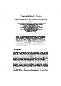
building codes and domain knowledge”. Solibri Inc. provides the integration of user-specific rules as a consultancy service, as realized, for example, in case of the implementation of the GSA accessibility framework (Eastman, 2009). However, the extension of the rule base directly by users is not intended. In (Kim & Grobler, 2009) an ontology-based approach for representing requirements and constraints of a project is presented. The authors propose to employ an ontology reason mechanism to detect conflicts between diverging participants’ requirements in collaborative design scenarios. Unfortunately, the paper discusses only very basic quantitative constraints, such as limits on a slab’s thickness. In (Borrmann, 2004) a declarative constraint definition language for digital building models with dynamic data models has been presented. However, the presented language allows only the specification of simple constraints based on attribute values and relations and does not provide support for spatial constraints. The necessity for formalizing client requirements has been extensively discussed by Kiviniemi (2005). He has developed a requirements model specification which can be linked to a building-product-model-based design model of the project. 3 Spatial constraints Spatial constraints form an important intermediate level of abstraction, between the quantitative properties of building geometry (vertex coordinates etc.) as encoded in the building information model and the way humans reason about building and the relations between their components (Figure 1).
Figure 1: Spatial constraints form an intermediate layer of abstraction
Many construction codes and regulations make use of spatial constraints, e.g. “There must be insulation below the ground slab.”, “A heat and smoke vent has to be located directly above the exit staircase.” etc. We distinguish three different types of spatial constraints: •
distance constraints
•
directional constraints
•
topological constraints
Distance constraints rely on the Euclidean metric and specify the maximum or minimum distance between two building elements. The spatial operators available for defining metric constraints are distance, closerThan, fartherThan, and maxDist. They have been formally defined in (Borrmann et al., 2009). Directional constraints may be used to restrict the directional relationship between two building elements. As underlying directional predicates we provide above, below, northOf, southOf, eastOf, westOf. Since in human communication, the assignment of a directional predicate relies on the assumptions and the context the users have in mind, the semantics of 3
the predicates have been defined within two different directional frameworks, the projectionbased and halfspace-based model (Borrmann & Rank, 2009). The models differ in the way they form individual space partitions to which to one of the directional predicates is assigned. Beyond that, there are two different flavours of the directional operators: The strict version requires the entire target object to be located within the respective space partition, in case of the relaxed version a part of the target object suffices. Topological constraints restrict the topological relationship between two building elements, i.e. those relationships which are invariant under affine transformations, such as translation, rotation and scaling as well as any combination of them. For the mutual exclusive topological predicates touch, contain, within, overlap, equal and disjoint formal specifications on the basis of the 9-intersection model have been given in (Borrmann & Rank, 2008). 4 Consistency and requirement constraints In general, we distinguish two fundamentally different types of constraints: Consistency constraints and Requirement constraints. Consistency constraints result from spatial (geometric or topological) references in the BIM data model. A typical example is the containment relationship, which is modelled in IFC by the IfcRelContainedInSpatialStructure objectified relationship. In general, the data model allows setting this relationship also for elements that are not contained within each other. This may result in inconsistencies between the geometric and the semantic representation with severe consequences for applications relying on these spatial relationships. By applying the spatial constraint checking techniques presented here, these kinds of inconsistencies can be detected and fixed. Other relationships of the IFC data model with spatial semantics are IfcRelConnectsElements, IfcRelCoversBldgElements, IfcRelCoversSpaces, IfcRelFillsElement, IfcRelVoidsElement and IfcRelSpaceBoundary, for example. Consistency constraints are generic, i.e. not project-specific. Requirements constraints, on the other hand, represent building codes, regulations, best-practise construction rules, or client requirements, which may vary from project to project. A typical example for a requirement constraint with spatial semantics would be “the kitchen in the second storey must be directly above the kitchen in the first storey”. 5 Constraint checking in collaborative design process The proposed concepts are based on the assumption that a central model repository such as an IFC model server is used for central model maintenance and design coordination. Basically we distinguish two different modes of maintaining constraints in conjunction with a building information model. In the first mode, the constraints are stored as part of the building model, using for example IfcConstraint objects. This allows detecting conflicts during the work on a local copy of the building model provided that there is constraint checking engine available. In the second mode, the constraints are stored in a separate rule base which is located at the central information repository. In this case, constraints are only validated when the building model is checked-in at the central repository. The third option is a hybrid mode, where constraints are stored in the BIM but validated only during the check-in procedure. Whenever a constraint violation occurs, it has to be resolved manually. Either by modifying the BIM in a way it complies with the defined constraints, or by removing the violated constraints. If the violated constraint has been defined by another participant, the design conflict has to be resolved through classical negotiation techniques supported by communication via phone or email. 4
A typical example scenario where a constraint with spatial semantics is used in a collaborative design process would look as follows: First an HVAC engineer places a water line at the top side of a certain room. Later, the interior architect inserts a suspended ceiling below the water line and, at the same time, sets the constraint “ceiling below water line”. When even later, the HVAC engineer again modifies the position of the water line such that it becomes located below the ceiling, a constraint violation is detected and communicated to the HVAC engineer. Besides constraint violation, also contradictions between constraints which are defined by different participants have to be detected. Let’s assume, in an abstract example scenario, three different participants: The first one sets a constraints that demands “object A above object B”, the second one “B above C” and the third one “C above A”. As soon as the third constraint is entered into the rule base, the constraint checking engine has to detect the contradiction and inform the user accordingly. Besides requirement constraints defined by the users, also consistency constraints have to be checked each time a BIM model is checked-in at the central repository. This is equivalent to a successful compilation of program code which is required in collaborative software development projects before a new version can be checked-in at the code repository. In that case, the compiler acts as a consistency check engine. 6 Constraint representation in IFC With release 2.0, the Industry Foundation Classes started to provide support for capturing constraints in digital building models. Currently, in IFC2x3 release, the IfcConstraintResource schema has been integrated, providing the entities IfcConstraint, IfcMetric and IfcObjective which can be associated with objects deriving from IfcRoot, including IfcControl (Figure 2). In the IFC model, constraints may be either qualitative (represented by an IfcObjective) or quantitative (represented by IfcMetric). A qualifier can be applied to an objective constraint that determines the purpose for which it is applied (CodeCompliance, DesignIntent, HealthAndSafety, Requirement, Specification, and TriggerCondition). An IfcObjective is applied to define the constraining values beyond which building codes may be violated or to limit the selectable range of values as in a specification (e.g. value of d must be greater than a but less than b). A set of benchmark values can be specified for the objective constraint and a set of result values captured for performance comparison purposes. An IfcMetric defines the actual value or values of a constraint. Values can be defined in terms of a benchmark requirement which sets the intent of the constraint i.e. whether the benchmark is greater than (>), less than (