IEEE JOURNAL OF SELECTED TOPICS IN QUANTUM ELECTRONICS, VOL. 19, NO. 5, SEPTEMBER/OCTOBER 2013
1702010
Spatial-Mode Discrimination in Guided and Antiguided Arrays of Long-Wavelength VCSELs Tomasz Czyszanowski, Robert P. Sarzała, Maciej Dems, Jarosław Walczak, Michał Wasiak, Włodzimierz Nakwaski, Vladimir Iakovlev, Nicolas Volet, and Eli Kapon
Abstract—Three means of optical confinement imposed on InAlGaAs/InP 1.3 μm VCSEL arrays are investigated with selfconsistent numerical model of laser operation. Laterally patterned tunnel junction (TJ), in-build guiding realized with air-gap patterning, and antiguiding schemes are investigated and optimized to achieve single-mode operation. The analysis shows that mode discrimination in laterally patterned TJ is very responsive to the injected current, the air-gap patterning reduces influence of the working conditions and supports multimode operation, and finally, antiguiding schemes provide single-mode operation for prescribed geometrical design. Index Terms—Laser arrays transverse optical modes, verticalcavity surface-emitting lasers (VCSELs).
I. INTRODUCTION IGH-power single-mode vertical-cavity surface-emitting lasers (VCSELs) present many benefits, as coherent optical sources enabling smooth tuning of wavelength with current and temperature. Emerging applications include inexpensive and portable devices used in sensing, imaging, telecommunications, etc. For these applications, it is preferable to have a large side-mode suppression ratio (SMSR) and high-power VCSELs. It is very difficult, however, to combine both properties in one device. For GaAs/AlGaAs-based VCSELs, the control of large SMSRs can be achieved using well-established wet oxidation technology, which makes possible single-mode operation only for relatively narrow apertures, typically providing less than 5 mW of output power [1]. Other methods providing higher emitted power and single-mode operation exploit microoptical structures: surface relief (12 mW) [2], antiresonant patterning (7 mW) [3], patterned tunnel junctions (TJs,
H
Manuscript received December 3, 2012; revised January 24, 2013; accepted February 15, 2013. This work was supported by the Swiss National Science Foundation (SNF) under Grant SCOPES IZ73ZO_128019. T. Czyszanowski, R. P. Sarzała, M. Dems, J. Walczak, M. Wasiak, and W. Nakwaski are with the Photonics Group, Institute of Physics, Lodz University of Technology, 90-924 Lodz, Poland (e-mail: tomasz.czyszanowski@p. lodz.pl;
[email protected];
[email protected]; jaroslaw.walczak@ p.lodz.pl;
[email protected];
[email protected]). V. Iakovlev and E. Kapon are with BeamExpress SA, CH-1015 Lausanne, ´ Switzerland, and also with the Laboratory of Physics of Nanostructures, Ecole Polytechnique F´ed´erale de Lausanne, CH-1015 Lausanne, Switzerland (e-mail:
[email protected];
[email protected]). ´ N. Volet is with the Laboratory of Physics of Nanostructures, Ecole Polytechnique F´ed´erale de Lausanne, CH-1015 Lausanne, Switzerland (e-mail:
[email protected]). Color versions of one or more of the figures in this paper are available online at http://ieeexplore.ieee.org. Digital Object Identifier 10.1109/JSTQE.2013.2251324
6 mW) [4], and photonic crystals (3 mW) [5]. Considerably higher levels of emitted power can be achieved using broadarea VCSELs (nearly 100 W under pulse operation [6] and 3 W under continuous operation [7]) at the expense of a broad emission spectrum. Vertical-external-cavity surface-emitting lasers (VECSELs) [8] offer another approach to reaching a considerably larger power and narrow spectral width. Their drawbacks are high power consumption and bulky construction encompassing an output coupler and an etalon to reduce the width of the laser spectrum, in addition to the external laser pump. A compromise method of achieving a compact, low-cost solution with moderate electric power consumption, which is able to emit a high-power beam with large SMSR, is to combine several emitters into a phase-locked array [9]. The vertical geometry of the device assures a narrow linewidth by the selection of a single longitudinal standing wave, in resonance with the quantum wells emitting at the active region. The sole mechanism enabling linewidth broadening originates from the existence of transverse modes of two kinds. The first are the modes of the single emitter; the second are the array’s supermodes, which are the linear combination of the modes of the single emitter [10]. The key to narrow spectral linewidth is to control the number of these two kinds of mode. The first kind can be controlled by varying the dimension of the single emitter or by patterning the optical confinement. Controlling the second kind of mode is far more problematic. Since 1985, when the groundbreaking work on VCSEL arrays by Uchiyama and Iga [11] was published, there has been a significant number of works investigating these devices both experimentally [12]–[14] and theoretically [15]–[17]. Only few representative reports are cited here. Nevertheless, theoretical analysis of VCSEL arrays has been limited to the separate considerations of thermo-electrical or optical phenomena. There is thus a need for parametrical analysis, which combines in a self-consistent manner thermal, electrical, and optical threedimensional models. This paper presents an analysis of optical confinement and carrier injection in VCSEL arrays aimed at the optimization of single-mode operation. We investigate three methods of mode confinement: thermal focusing, in-build waveguiding, and antiresonant reflecting optical waveguiding (ARROW). Although only one design provides strong single-mode operation, we investigate very carefully all means of the optical confinement to analyze the physical reasons for different spectral characteristics of VCSEL arrays. We assume strong mode discrimination and a narrow lasing spectral width as criteria for evaluating confinement methods. Conclusions about possible optimal designs are derived.
1077-260X/$31.00 © 2013 IEEE
1702010
IEEE JOURNAL OF SELECTED TOPICS IN QUANTUM ELECTRONICS, VOL. 19, NO. 5, SEPTEMBER/OCTOBER 2013
TABLE I PHYSICAL PARAMETERS USED IN THE SIMULATION AT 300 K (∗—THE VALUE HAS BEEN FOUND FROM THE COMPARISON OF THE MODEL WITH EXPERIMENT)
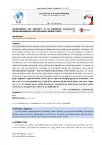
Fig. 1. Schematic view of considered designs (cross sections): (a) tunneljunction VCSEL array, (b) air-gap tunnel-junction VCSEL array, (c) antiresonant reflecting optical waveguide tunnel-junction VCSEL array. The insets in the upper part of each panel show top views of the patterned structures. The separation between the emitters (L) and the coordinate system applied in the analysis of all the three designs are shown in (a). The etching depth (dE ) of air-gap patterning is defined in (b)
II. VCSEL ARRAY STRUCTURE AND NUMERICAL MODELS The analyzed structure (see Fig. 1) [13] incorporates InAlGaAs quantum wells within an InP cavity. The cavity is bounded by 35 pairs of Al0.9 Ga0.1 As/GaAs DBRs from the bottom and 20 pairs of Al0.9 Ga0.1 As/GaAs DBRs from the top. Laterally patterned TJ layers are responsible for funneling carriers into the active region and for the resultant separately defined emitters (pixels). In the analysis, we consider 3 × 1 VCSEL arrays, which are composed of three square-shaped TJ mesas of dimensions 6 μm × 6 μm as shown in Fig. 1. The emitted wavelength of this TJ VCSEL array, close to the threshold, is about 1310 nm. To simulate rigorously the physical phenomena taking place in the device, we use a multiphysical model [18], [19], which comprises three-dimensional models of optical (plane wave admittance method), thermal, electrical, and diffusion phenomena (all the three based on finite-element method). Such comprehensive model allows to determine the modes which are strongly enough confined to appear in the laser spectrum. The model used in the analysis is very well suited for that goal since precisely includes
all physical phenomena contributing to the modifications of the refractive index distribution in the laser. The model does not determine which modes are lasing, but which of them have potential to lase. Such an approach allows determining the maximal broadening of the laser spectrum, which does not change if the analysis includes spatial hole burning (SHB). SHB is the process which introduces competition between the modes but it does not change their wavelengths. Moreover the parametrical study in which SHB is included would lead to the critical increase of the computational requirements. In the past only simpler models were used in parametrical studies of VCSEL arrays [15]–[17]. The simplification of the model by ignoring electrical or thermal phenomena leads to neglecting thermal focusing, which is an important mechanism responsible for confining the modes. The model used in the analysis is the a tradeoff allowing for precise and extensive analysis of large range of the construction parameters. The material parameters used in the analysis are shown in Table I. The optical confinement methods mentioned earlier are illustrated in Fig. 1. In the structure without any lateral in-build distribution of the refractive index, thermal focusing is the dominant process. Such a structure is illustrated in Fig. 1(a). Only the
CZYSZANOWSKI et al.: SPATIAL-MODE DISCRIMINATION IN GUIDED AND ANTIGUIDED ARRAYS
TJ layer provides here a nonuniform distribution of the refractive index in the lateral x-y direction. In the fabrication process, a highly doped InAlGaAs layer is etched to form separate islands and then overgrown with InP to provide the patterned TJ structure [13]. The contrast between the refractive indexes of the TJ InAlGaAs layer and the neighboring InP layer is 0.2. The influence of the refractive index contrast on the lateral-mode distribution is significantly reduced by placing the TJ layer in the node of the standing wave. Hence, the dominant effect responsible for the confinement of the modes is thermal focusing. In the structure of the TJ VCSEL array, the dominant parameters affecting the modal characteristics and the modes distributions are the separation between the TJ squares (L) and the injected current (I). Both are investigated here in the broad range of values: 0 < L < 4 μm and 11 mA < I < 30 mA. Air-gap patterning, which is introduced at the interface between the cavity and the top DBR [see Fig. 1(b)], is responsible for further stabilizing the mode distribution, rendering it independent of thermal focusing [31]. The air-gap patterning is designed in such a way as to create separate windows for each emitter. Hence, the dominant effect on modal characteristics and optical-mode distribution is caused by the geometry of the airgap patterning. In the case of an air-gap tunnel-junction (AG TJ) VCSEL array, one should evaluate the effect of the etching depth and the distance between the emitters (L), since an increase in both the parameters strengthens the optical confinement effect and causes corresponding modifications in the mode parameters. However, evaluation of the mode confinement driven by a change in etching depth (dE ) is more instructive, since this shows the mode evolution from a weak confinement case driven by thermal focusing to a strong confinement governed by an etching depth of 180 nm. The third design that we analyze utilizes an ARROW scheme, which is also introduced by patterning the interface between the cavity and the top DBR, covering the TJs [see Fig. 1(c)]. In the simulations, we assumed that the low-refractive-index material used to create the ARROW structure is ZnSe [32], represented by a refractive index equal to 2.46 [33]. In the ARROW TJ VCSEL, the mode is confined laterally by the constructive interference of the light reflected from the interfaces, between the islands of low and the regions of high refractive index. Such a mechanism favors selectively modes in resonance with the ARROW structure, which is expected to be the origin of strong discrimination. Since here interference is the mechanism governing beam confinement, the distance between the low refractive index islands (L) is crucial in assuring resonance conditions. III. CURRENT INJECTION AND TEMPERATURE DISTRIBUTION The current flow and the recombination of carriers are the main sources of heat generation in lasers and are taking place in their active regions. Heat is generated by the nonradiative recombination processes in the quantum wells and by the Peltier effect at the edges of the active region, where the carriers cross near the 0.5 eV energy step from the InP cladding to the InAlGaAs barrier. Their kinetic energy is dissipated through the phonons contributing to the heating of the structure. These
1702010
Fig. 2. Distributions of the temperature (left column) in the plain perpendicular to the active region (x–z plane) and carrier concentration (right column) in the active region under current injection equal to 20 mA for three different distances between emitters [(a) and (b)] L = 0.1 μm, [(b) and (c)] L = 4.0 μm, and [(e) and (f)] L = 8.0 μm.
processes, as well as the volume Joule heating in all structure layers and the barrier Joule heating in the contacts have been taken into account in our analysis. Fig. 2 illustrates the calculated temperature distribution in the TJ VCSEL array [see Fig. 1(a)]. In the calculations, we vary the distance between the emitters (L) in the range from 0.1 to 8 μm. The heat generated in the active region is transferred through the substrate to the heat sink, and only a very small part of it is transported to the top DBR, where the heat is dissipated by the convection process. The distance between emitters affects predominantly the temperature distribution within the VCSEL, which governs the distribution of the refractive index. The transition from a small to a large distance (8 μm in our analysis) between emitters modifies the temperature and the refractive index distributions (see Fig. 2). In the case of a small distance [see Fig. 2(a)], the temperature distribution is very similar to that observed in broad area VCSELs, so pixels do not behave as separate heat sources. An increase in the distance between emitters leads to a weaker overlap of the temperature distributions of neighboring emitters and to more pronounced thermal separation of the emitters. In this case, three peaks in the temperature can be observed on top of the dominant central peak [see Fig. 2(b)]. An even larger distance between emitters [see Fig. 2(c)] reduces the thermal interaction between emitters, which is manifested in a drop in the temperature between the emitters. In the case of close packing of the emitters, the heat transfer is somewhat hampered, while a large distance between emitters broadens the heat path to the heat sink and leads to a more
1702010
IEEE JOURNAL OF SELECTED TOPICS IN QUANTUM ELECTRONICS, VOL. 19, NO. 5, SEPTEMBER/OCTOBER 2013
Fig. 3. Maximal temperature (T m a x ) in the active region as the function of the distance between emitters (L) in the case of TJ VCSEL [see Fig. 1(a)] under 20 mA injection.
intense heat flux. Increasing the distance between the emitters contributes to a reduction of the maximal temperature (see Fig. 3). However, the reduction of the maximum temperature is not the dominant effect affecting the modal characteristics, but rather the change in temperature distribution is more significant. The calculated threshold current of the single TJ VCSEL of the same vertical design as shown in Fig. 1(a) and square-shaped TJ of dimension 6 μm × 6 μm equals 3 mA, while the threshold current of TJ VCSEL array is slightly above 6 mA. The modification of the carrier concentration within the active region, due to change in the emitter separation, reveals a transition from the distribution similar to a single, broad aperture laser [see Fig. 2(b)], through intermediate distribution [see Fig. 2(d)], to the distribution typical of separate, nearly independent emitters [see Fig. 2(f)]. The carrier density is very uniform within each emitter. It is mostly driven by the geometry of the contacts and by the use of the TJ, which reduces the amount of p-layers and eliminates the current crowding effect through a very high doping level. Consequently, the gain distribution is close to a Gaussian distribution, as a result of diffusion in the active region. The SHB effect (SHBE) is not considered in our analysis, which focuses on providing an exhaustive parametrical study of the different VCSEL array designs, and on methods of mode confinement. In the case of multimode operation, the numerical analysis of SHBE is extremely time consuming since the mode competition is a strongly nonlinear phenomena. Moreover, the influence of the distribution of the carriers on the optical confinement mechanism is dominated by thermal focusing, which occurs not only in the active region but also in the whole volume of the device. SHBE is responsible for governing mode competition; however, its influence on the shape of particular modes is almost imperceptible. In the present analysis, we have decided to keep a constant level of carriers in the active region, regardless of the current injection, and to maintain all the other current dependences on (to mention only the most dominant) heat generation, the refractive index, on gain, electrical conductivity, and on thermal conductivity. In such an approach, the determination of the modal gain provides information on the modes interaction with the active region. The modes that are strongly confined acquire large modal gain due to their large overlap with the gain in the active region. Another approach, in which one would neglect the SHBE and take into account the
realistic relation between current injection and carrier concentration in the active region, would lead to an unrealistic increase in modal gain, which should be zero while lasing, due to the balance between generated and emitted/absorbed photons. We have therefore chosen an intermediate approach in which we find a level of injection close to the threshold for a typical design and use the same current injection to calculate the diffusion of carriers in a plethora of designs. This allows us to reach close to the real level of the carriers in the active region and to significantly reduce the computational time neglecting SHBE. On the basis of the carrier distribution, we determine the spatial dependence of the gain taking into account the temperature distribution within the active region. This allows us to find the modal gains in the considered designs. Hence, our investigation determines: 1) the influence of thermal and in-built mode confinement on mode discrimination; 2) the set of the modes that are expected to be present in the lasing spectrum; 3) the spectral width that we define as the spectral distance between two extreme modes. The differences between the three analyzed structures are relatively insignificant with respect to the thermal and electrical properties. The AG and ARROW patterns responsible for optical confinement are distant from the current path; hence, they do not affect the current flow. Additionally, although both patterns are defined by smaller thermal conductivities as compared to that of InP (0.022 W/(m·K) for ZnSe and air an 18 W/(m·K) for InP), they are placed above the active region; hence, they do not affect the heat transfer to the heat sink. This explains the very similar distributions of the temperature within the three designs considered and nearly identical carrier distributions under the same level of injection. IV. TJ VCSEL ARRAY Properly designed single-emitter TJ VCSELs, considered here, typically provide single-mode operation from the threshold to the rollover [34] point. The resulting mode distributions may display mode patterns with more near-field lobes than TJ pixels, as illustrated in Fig. 4 for a three-pixel TJ VCSEL array. This figure shows the typical mode distributions considered in the analysis. These exemplary mode distributions in the plane of the active region have been calculated for the TJ VCSEL array [see Fig. 1(a)], under 20 mA current injection. Fig. 4(c) illustrates a so-called array mode ε0,2 defined by the number of lobes equal to the number of pixels. Such array mode is especially desired to achieve high efficiency of laser operation, since it provides the best overlap between the gain and the mode distribution. Fig. 5 illustrates the influence of the distance between the emitters on the modal characteristics for three different currents, which correspond to the proximity of the threshold (11 mA), intermediate excitation (20 mA), and near rollover (30 mA). Fig. 5(a) shows the wavelength of the possible modes, while Fig. 5(b) shows their modal gains. Low-level injection produces a moderate gradient in the temperature in proximity to the active region. A weak guiding mechanism confines very low order modes only. Fig. 5(b) shows two modes (ε0,0 , ε0,1 ) of the largest and relatively close modal gain
CZYSZANOWSKI et al.: SPATIAL-MODE DISCRIMINATION IN GUIDED AND ANTIGUIDED ARRAYS
1702010
Fig. 4. The normalised intensity distribution of the lowest order modes in the plane of the active region (x − y plane) in a TJ VCSEL array [Fig. 1(a)] under 20 mA current injection and L = 2 μm. White squares represents the borders of the tunnel junctions. (a) ε0 , 0 . (b) ε0 , 1 . (c) ε0 , 2 . (d) ε0 , 3 . (e) ε1 , 0 . (f) ε1 , 1 . (g) ε1 , 2 . (h) ε1 , 3 .
for designs with small distance between emitters. ε0,0 is the mode of the largest modal gain; however, it does not determine whether this mode dominates, since mode domination is eventually the result of mode competition due to SHBE, which is not considered here. However, the largest modal gain of ε0,0 indicates that the mode appears first above the threshold. The modal gain of ε0,1 is very close to that of ε0,0 and probably those two modes can be observed in the lasing spectrum, since ε0,1 is predominantly concentrated in the first and third pixel, while ε0,0 is located predominantly at the second pixel; hence, both the modes are fed by stimulated photons generated in the independent pixels. Their spectral distance is only 0.2 nm [see Fig. 5(a)], which yields a very narrow emitted spectrum. The third array mode ε0,2 is of relatively low modal gain, since the thermal focusing effect is too weak to efficiently confine the array mode and all other higher order modes characterized by significant modal absorption. An increase in the distance between the emitters allows for better overlap between broad modes (ε0,2 and ε0,3 ) and regions of positive gain. The modal gain of such modes increases with increasing distance between pixels, since the shift of the emitters is bigger than the broadening of the mode distribution. Such behavior reduces the absorption of the outer lobes. The modal gain of all other modes, whose distributions overlap the gaps between the TJ pixels, decreases since the gain between the emitters reduces with the increase in distance between pixels [see Fig. 2(b), (d), and (f)]. If the distance is larger than 2 μm, ε0,2 dominates with respect to the modal gain, since it becomes adjusted very closely to the gain distribution. Hence, for a distance between emitters larger than 2 μm three modes can be present in the spectrum, which makes the spectrum 0.3 nm wide. A further increase in the distance between the emitters reduces the spectral width to 0.25 nm [see Fig. 5(a)]. Increasing the injection level [see Fig. 5(c) and (d)] introduces stronger thermal focusing, which is manifested in spectral redshift [see Fig. 5(a) and (c)] and in the reduction of the modal gain difference between higher order modes: ε0,2 , ε0,3 , and ε0,4 [see Fig. 5(b) and (d)]. Additionally, the array mode becomes dominant in structures with a smaller distance between emitters
Fig. 5. [(a), (c), and (e)] Mode wavelengths and [(b), (d), and (f)] modal gains as a function of the distance between the emitters (L) for three different currents: [(a) and (b)] 11 mA, [(c) and (d)] 20 mA, and [(e) and (f)] 30 mA for the TJ VCSEL array [see Fig. 1(a)].
(L = 1.5 μm). ε0,0 , ε0,1 , and ε0,2 are modes of the largest and closest value to the modal gain in the case of small distances [see Fig. 3(d)], so the spectrum of the emitted beam is of 0.6 nm width. For larger distances between emitters, the array mode becomes more preferable since the gain between emitters reduces, eliminating lower order modes, and ε0,2 reveals the best overlap with the gain distribution. The modal gain difference between ε0,2 and ε0,0 reaches 3.3 cm−1 . If such a modal gain difference can be reduced by the mode competition, then one expects a 0.3 nm spectral width containing three modes. Otherwise, the emitted beam would contain a single mode. A very strong injection, close to the rollover point, produces an even stronger thermal focusing, which confines additionally ε0,3 . The emitted spectrum can be composed of at most four modes, both for small and large distance between emitters. ε0,2 is of largest modal gain; however, the difference with respect to other modes is not significant and one can expect that mode competition can lead to the coexistence of four modes in the spectrum. Hence, the spectrum is expected to be 1.2 and 0.6 nm wide in the case of small and large distances between the emitters, respectively. V. AG TJ VCSEL ARRAY The main disadvantage of the TJ VCSEL array [see Fig. 1(a)] is a lack of efficient control on the lateral-mode field distributions. The desired array mode distribution does not overlap the
1702010
IEEE JOURNAL OF SELECTED TOPICS IN QUANTUM ELECTRONICS, VOL. 19, NO. 5, SEPTEMBER/OCTOBER 2013
Fig. 6. The normalised intensity distribution of selected modes within the plane of the active region (x-y plane) for different etching depth of the patterning in an AG TJ VCSEL array structure [see Fig. 1(b)]. The columns correspond to different etching depths (dE ) of AG (left column) dE = 0.02 μm, (central column) dE = 0.08 μm, and (right column) dE = 0.18 μm. White borders represent the borders of the AG patterning. The inner squares relate also to the borders of TJ.
positive gain distribution well, since it is too broad under low levels of injection, or it must compete with higher order modes under strong thermal focusing, induced by a high level of injection. We will investigate here whether the introduction of the etched pattern at the interface between the cavity and the top DBR would structure the array mode and discriminate against the modes of which the lobes do not correspond to the etching pattern. Such possibility is provided by the AG TJ VCSEL array. We assume the same structure as that of TJ VCSEL array with the air-gap patterning introduced at the interface between cavity and top DBR [see Fig. 1(b)]. The optical confinement mechanism governed by the etched pattern is limited to a small part of the cavity only, which is thinner than 200 nm. On the other hand, the confinement mechanism triggered by thermal focusing affects the whole structure. However, the first mechanism introduces a refractive index difference of four orders of magnitude larger than the second; and according to the calculations, the influence of thermal focusing on the mode distribution is eliminated in such designs for an etched pattern deeper than 50 nm. Hence, to highlight the essential influence of air-gap confinement on modal characteristics, we will focus on an analysis of the etching depth varying in the range from 0 to 180 nm under a constant level of injection, which we will set equal to 11 mA. The distance between the emitters (L) is set at 0.4 μm. Larger distance causes weak interaction between the emitters. Fig. 6 shows the near-field distributions of the selected modes in the AG TJ VCSEL array for different etching depths. First column illustrates the distribution of the modes for shallow etching depth of 0.02 μm, which nearly does not affect the mode distributions with respect to the ones in the corresponding
Fig. 7. (a) Mode wavelengths and (b) modal gains as a function of the etching depth dE for 11 mA current in AG TJ VCSEL [see Fig. 1(b)].
TJ VCSEL array. The central column relates to 0.08 μm etching depth, which further confines the modes, and the lobes of the modes become weakly localized in the pixels. The right column (0.18 μm etch depth) shows strong confinement of the modes and lobes of the modes become strongly localized in central or outer pixels. Fig. 7 displays the (a) wavelengths and the (b) modal gains of the modes supported by the structure as a function of the etching depth dE . The increase in etching depth brings about the confinement of higher order modes. The lack of an air gap under 11 mA current injection allows only two modes (ε0,0 , ε0,1 ) to be confined strongly enough to reach the threshold. Increasing the etching depth increases confinement, which supports lasing of higher order modes. Another consequence of increasing the etching depth is a blueshift of the emission wavelength, which is also typically observed in single-emitter VCSELs and is driven by strengthening of the optical confinement [35]. The most characteristic behavior observed in the case of air-gap VCSEL arrays is the grouping of the modes. Fig. 7(a) shows that spectrally separated modes in the case of shallow etching tend to be collected in groups under deep etching. These groups are spectrally 1–2 nm apart, which is a typical spectral separation in the case of single-emitter air-gap VCSELs of 6 μm × 6 μm aperture. Each group consists of several modes, which spectral separation is of the order of 0.05 nm. All the modes are strongly confined; hence, their modal gains are close and large [see Fig. 7(b)]. Therefore, one can expect
CZYSZANOWSKI et al.: SPATIAL-MODE DISCRIMINATION IN GUIDED AND ANTIGUIDED ARRAYS
that depending on the mode competition many of those modes contribute to the laser spectrum. As a consequence, the VCSEL array spectrum resembles a comb consisting of several separated teeth. The small spectral separation of the modes in the tooth/group can be explained by the fact that an increase in the etching depth reduces the interaction between the pixels and the modes tend to single-emitter-like distribution within the pixel. The modes, which are defined by the same number of lobes in the pixel, create common groups. Moreover, strongly confined modes are located either in the single, central pixel or in the two outer pixels. Below, we show the modes that create separate groups with respect to the number of the lobes in the pixels. The numbers in the parentheses assign whether mode occupies single pixel (1) or two pixels (2): ε0,0 (1), ε0,1 (2), ε0,2 (2) → 1 lobe group ε0,3 (1), ε1,0 (1), ε1,1 (2), ε0,4 (2), ε1,2 (2), ε0,5 (2) → 2 lobes group ε1,3 (1), ε1,4 (2), ε1,5 (2) → 4 lobes group ε2,0 (1), ε2,1 (2), ε0,6 (1), ε0,7 (2), ε0,8 (2)→ 3 lobes group.
1702010
Fig. 8. Mode wavelength and modal gain of ε0 , 8 mode as a function of the distance between the emitters (L) for 11 mA current in ARROW TJ VCSEL [see Fig. 1(c)]. The vertical lines determine the borders of the L-regions for which the distribution of the mode is stationary with respect to the number of lobes occurring in the particular pixels.
VI. ARROW TJ VCSEL ARRAY None of the previously analyzed designs reveals strong-mode suppression. This shows that the confinement mechanism in those structures is not selective and confines all the modes roughly equally, reducing their discrimination. Antiresonantbased designs achieve strong-mode discrimination [36]–[39] at the expense, however, of large modal losses, originating in the lateral leakage of the modes. The confining mechanism is based on the coupling of lateral leaky modes, which adjust to the interfaces between the lateral regions of different refractive indexes in a very similar way as the standing wave in the vertical direction of the VCSEL. Hence, such a mechanism is selective with respect to the lateral-mode distribution and can be tuned by changing the distance between emitters (L). We investigate here the influence of this distance on the modal characteristics of an ARROW TJ VCSEL array [see Fig. 1(c)]. The structure is based on the TJ VCSEL array design with the addition of 138-nm-thick ZnSe islands overgrown at the interface between cavity and top DBR. The thickness of the ZnSe islands relates to quarter-wavelength, and they are placed at the interface between the cavity and the semiconductor DBR to additionally support the reflection from the top DBR. Lateral positions and dimensions of the ZnSe islands are identical to that of the TJ islands. Similar to the analysis of the AG TJ VCSEL array, the contrast of the refractive index produced by the ARROW structure is several orders of magnitude larger than the gradient induced by thermal focusing, and our analysis showed that its influence on the mode distribution is insignificant. The calculations were also performed under a constant level of injection, which we set at 11 mA. To analyze the mode modifications caused by a change in the distance between emitters, we can trace the changes of the arbitrarily chosen mode ε0,8, which is the in-phase mode desirable with respect to the quality of the far field. Additionally, being of high-order mode ε0,8 is a particularly interesting since the modifications of the mode distribution are very illustrative representing the transformations that concern all the modes in
Fig. 9. The ε0 , 8 normalised mode distributions in the plane of the active layer in the regions (a)–(f) depicted in Fig. 8 for 11 mA current. White squares represents the borders of ZnSe islands and TJs. TABLE II CHARACTERIZATION OF ε0 , 8 DISTRIBUTION WITH RESPECT TO THE DISTANCE BETWEEN EMITTERS (L)
the structures of the ARROW TJ VCSEL arrays. Fig. 8 shows the influence of the distance between the emitters (L) on the wavelength and modal gain of ε0,8 . One can determine the ranges of L for which the distribution of the mode is stationary with respect to the number of lobes occurring in the particular pixels (see Fig. 9). Each of these regions, which we call L-regions, is nearly 1 μm wide. The number of lobes of ε0,8 in the consecutive pixels are given in Table II. L-regions a and b (see Fig. 8) correspond to the distribution of the mode with three lobes in the central pixel [see Fig. 9(a) and (b)], while c, d, and e (see Fig. 8) correspond to one lobe in the central pixel [see Fig. 9(c)–(e)]. This shows that L-region d (see Fig. 8) is the most desirable
1702010
IEEE JOURNAL OF SELECTED TOPICS IN QUANTUM ELECTRONICS, VOL. 19, NO. 5, SEPTEMBER/OCTOBER 2013
Fig. 10. The ε0 , 8 normalised mode distributions in the plane of the active region at the interfaces c–d and d–e depicted in Fig. 8 for 11 mA current. White squares represents the borders of ZnSe islands and TJs. Red color corresponds to the maximal intensity of light.
with respect to the mode distribution [see Fig. 9(d)], which overlaps in the most efficient way the gain distribution, and it is defined by a low level of modal loss (see Fig. 8). The only imperfection in the mode distribution in L-region d (see Fig. 8) is the nonuniformity of the intensity peaks [see Fig. 9(d)]. These become uniform at the transition points between L-regions c-d and d-e only (see Fig. 8). The corresponding distributions of the modes are shown in Fig. 10. The modal gain function (see Fig. 8) reveals deep minima between the L-regions related to the small distance between the emitters (L-regions a, b, and c). The transition points between L-regions a-b and b-c relate to the unconfined mode distributions with enormous modal losses. The wavelength of the mode changes abruptly at the transition points between the L-regions a-b and b-c. They relate to three lobes in the central pixel [see Fig. 9(a) and (b)]. Further transition points between the L-regions related to one lobe in the central pixel [see Fig. 9(c)–(e)] can be noticed only as small dips in the modal gain function (see Fig. 8). The function of the wavelength remains almost constant in L-regions d and e. Although one can observe considerable changes in the mode distribution throughout L-regions a-f (see Fig. 8), we follow ε0,8 , which consists of nine lobes clearly visible in L-region a only [see Fig. 9(a)], where all lobes have nearly equal amplitudes. The transition between L-regions relates to the migration of two lobes in the space between emitters and the reduction of their amplitudes. L-region f relates to a situation in which the last lobe remaining in the central pixel migrates to the space between the pixels, which is equivalent to a deterioration of the mode. Fig. 11 illustrates the dependence of wavelength and modal gain on the distance between the emitters (L) of several, lower order, even modes. The odd modes have not been included in the figure since they suffer from significant modal losses due to their distribution. All the modes reveal similar behaviors but their plateau on the wavelength and maximal modal gain L-regions are shifted. This facilitates strong mode discrimination. Small distance between emitters (L) supports strong discrimination. We can notice the out-of-phase mode ε0,2 being dominant for L = 0.8 μm (∼10 cm−1 discrimination), while the in-phase mode ε0,4 becomes dominant for L = 1.6 μm (∼6 cm−1 discrimination). A larger distance between emitters no more supports the domination of a single mode but rather supports pairs of the modes. Then, the modal gain difference between the pair of the dominating modes and others is of the order of 10 cm−1 . The spectral distance between couple modes is typically smaller than 0.5 nm. These pairs consist of two neighboring even modes,
Fig. 11. (a) Mode wavelengths and (b) modal gains as a function of the distance between the emitters (L) for 11 mA current in ARROW TJ VCSEL.
which are in- and out-of-phase modes. Such behavior allows the design of single-mode ARROW TJ VCSEL arrays with relatively small distances between emitters. The construction hampers efficient heat extraction from the active region. A larger distance between the emitter would favor more efficient devices allowing for stable, two-mode emission. VII. CONCLUSION Using a three-dimensional, self-consistent model of physical phenomena in VCSELs, we have investigated three means of optical confinement in VCSEL arrays: thermal focusing observed in the laterally patterned tunnel-junction (TJ VCSEL array), in-build guiding realized in air-gap patterning (AG TJ VCSEL array), and antiguiding implemented by low-refractiveindex material overgrowth (ARROW VCSEL array). We have investigated the crucial parameters for these designs, which affect the strongest mode distribution and modal characteristics. In the case of TJ VCSEL arrays, it was the distance between the emitters and the level of the injection; in the AG TJ VCSEL array, we investigated the influence of the etching depth; finally, in the ARROW TJ VCSEL array, we considered the distance between the emitters. All the investigated means of confinement were imposed on the InAlGaAs/InP 1.3 μm VCSEL structure. The analysis showed that, in the case of TJ VCSEL array, a distance between the emitters larger than 2 μm supports singlemode operation under some injection levels. The maximal mode
CZYSZANOWSKI et al.: SPATIAL-MODE DISCRIMINATION IN GUIDED AND ANTIGUIDED ARRAYS
discrimination reaches 3.3 cm−1 and the emitted mode is out of phase ε0,4 . The width of the spectrum increases with the injection level and with a reduction in the distance between the emitters and may reach 2 nm. The AG TJ VCSEL is defined by the largest modal gain induced by a strong, in-build waveguide mechanism. The same mechanism of strong waveguiding is responsible for the disappearance of mode discrimination. Under strong confinement, the modes tend to be localized in the central or outer pixels and to convert into a typical single-emitter mode distribution. The light emitted forms spectral combs where each tooth is a group of modes, each with the same number of lobes in a single pixel. The spectral distance between the two extreme modes of one tooth is 0.3–0.5 nm, while the distance between the teeth is 1–2 nm. The ARROW TJ VCSEL array suffers from the largest modal losses due to the typical leakage of its modes. Strong mode discrimination was observed in the range of 10 cm−1 for out-of-phase and 6 cm−1 for in-phase modes, in the case of distances less than 2 μm between the emitters. Larger distances support two-mode operation. Pairs of inand out-of-phase modes are strongly discriminated from other modes, while the modal gain gap reaches up to 10 cm−1 . The spectral separation of the couple is less than 0.5 nm, and under carefully designed parameters, it can further be reduced.
REFERENCES [1] C. Jung, R. J¨ager, M. Grabherr, P. Schnitzer, R. Michalzik, B. Weigl, S. M¨uller, and K. J. Ebeling, “4.8 mW singlemode oxide confined top surface emitting vertical cavity laser diode,” Electron. Lett., vol. 33, no. 21, pp. 1790–1791, 1997. [2] A.-S. Gadallah and R. Michalzik, “High-output-power single-higher-order transverse mode VCSEL with shallow surface relief,” IEEE Photon. Technol. Lett., vol. 23, no. 15, pp. 1040–1042, 2011. [3] D. Zhou and L. J. Mawst, “High-power single-mode antiresonant reflecting optical waveguide-type vertical-cavity surface-emitting lasers,” IEEE J. Quantum Elect., vol. 38, no. 12, pp. 1599–1606, 2002. [4] E. Kapon and A. Sirbu, “Long-wavelength VCSELs. Power-efficient answer,” Nat. Photon., vol. 3, pp. 27–29, 2009. [5] P. S. Ivanov, P. J. Heard, M. J. Cryan, and J. M. Rorison, “Comparative study of mode control in vertical-cavity surface-emitting lasers with photonic crystal and micropillar etching,” IEEE J. Quantum Electron., vol. 47, pp. 1257–1265, 2011. [6] L. Zhang, Y. Ning, Y. Zeng, L. Qin, Y. Liu, X. Zhang, D. Liu, H. Xu, J. Zhang, and L. Wang, “High-Power bottom-emitting vertical-cavity surface-emitting lasers under continuous-wave, quasi-continuous-wave, and pulsed operation,” Appl. Phys. Exp., vol. 4, pp. 052102-1–052102-3, 2011. [7] L. A. D’Asaro, J.-F. Seurin, and J. D. Wynn, “High-power, high efficiency VCSELs pursue the goal,” Photonics Spectra, vol. 39, pp. 62–66, Laurin Publishing, 2005. [8] O. G. Okhotnikov, Semiconductor Disk Lasers, 1st ed. New York, NY, USA: Wiley-VCH, 2010. [9] M. Orenstein, E. Kapon, N. G. Stoffel, J. P. P. Harbison, L. T. Florez, and J. R. WullertII, “Two-dimensional phase-locked arrays of vertical-cavity semiconductor lasers by mirror reflectivity modulation,” Appl. Phys. Lett., vol. 58, pp. 804–806, 1991. [10] E. Kapon, J. Katz, and A. Yariv, “Supermode analysis of phase-locked arrays of semiconductor lasers,” Opt. Lett., vol. 9, pp. 125–127, 1984. [11] S. Uchiyama and K. Iga, “Two-dimensional array of GaInAsP/InP surfaceemitting lasers,” Electron. Lett., vol. 21, pp. 162–164, 1985. [12] L. D. A. Lundeberg, G. P. Lousberg, D. L. Boiko, and E. Kapon, “Spatial coherence measurements in arrays of coupled vertical cavity surface emitting lasers,” Appl. Phys. Lett., vol. 90, pp. 021103-1–021103-3, 2007.
1702010
[13] L. Mutter, V. Iakovlev, A. Caliman, A. Mereuta, A. Sirbu, and E. Kapon, “1.3μm-wavelength phase-locked VCSEL arrays incorporating patterned tunnel junction,” Opt. Exp., vol. 17, pp. 8558–8566, 2009. [14] D. F. Siriani and K. D. Choquette, “Implant defined anti-guided verticalcavity surface-emitting laser arrays,” IEEE J. Quantum Electron., vol. 47, no. 2, pp. 160–164, 2011. [15] M. Osinski and W. Nakwaski, “Thermal analysis of closely-packed twodimensional etched-well surface-emitting laser arrays,” IEEE J. Sel. Topics Quantum Electron., vol. 1, no. 2, pp. 681–696, 1995. [16] P. Debernardi, G. P. Bava, F. Monti diSopra, and B. M. Willemsen, “Features of vectorial modes in phase-coupled VCSEL arrays: Experiments and theory,” IEEE J. Quantum Electron., vol. 39, no. 1, pp. 109–119, 2003. [17] D. L. Boiko, G. Guerrero, and E. Kapon, “Thermoelectrical model for vertical cavity surface emitting lasers and arrays,” J. Appl. Phys., vol. 100, pp. 103102-1–103102-9, 2006. [18] M. Dems, R. Kotynski, and K. Panajotov, “Planewave admittance method—A novel approach for determining the electromagnetic modes in photonic structures,” Opt. Exp., vol. 13, pp. 3196–3207, 2005. [19] R. P. Sarzala and W. Nakwaski, “Optimization of 1.3 μm GaAs-based oxide-confined (GaIn)(NAs) vertical-cavity surface-emitting lasers for low-threshold room-temperature operation,” J. Phys., Condens. Matter, vol. 16, pp. S3121–S3140, 2004. [20] W. Nakwaski, “Thermal conductivity of binary, ternary and quaternary III–V compounds,” J. Appl. Phys., vol. 64, pp. 159–166, 1989. [21] S. Adachi, “Optical dispersion relations for GaP, GaAs, GaSb, InP, InAs, InSb, AlxGa1-xAs and In1-xGaxAsyP1-y,” J. Appl. Phys., vol. 66, pp. 6030–6040, 1989. [22] J. Piprek, J. K. White, and A. J. SpringThorpe, “What limits the maximum output power of long-wavelength AlGaInAs/InP laser diodes?,” IEEE J. Quantum Electron., vol. 38, no. 9, pp. 1253–1259, 2002. [23] R. F. Kazarinov and G. L. Belenky, “Novel design of AlGaInAs-InP lasers operating at 1.3 μm,” IEEE J. Quantum Electron., vol. 31, pp. 423–426, 1995. [24] S. Adachi, “GaAs, AlAs, and Al(x)Ga(1-x)As: Material parameters for use in research and device applications,” J. Appl. Phys., vol. 58, pp. R1–R29, 1985. [25] S. Gehrsitz, F. K. Reinhart, C. Gourgon, N. Herres, A. Vonlanthen, and H. Sigga, “The refractive index of AlxGa1-xAs below the band gap: Accurate determination and empirical modeling,” J. Appl. Phys., vol. 87, pp. 7825–7837, 2000. [26] S. Adachi, Physical Properties of III-V Semiconductor Compounds. New York, NY, USA: Wiley, 1992. [27] M. Amiotti and G. Landgren, “Ellipsometric determination of thickness and refractive index at 1.3, 1.55, and 1.7 μm for In(1 −x ) Gax As y P(1 −y ) films on InP,” J. Appl. Phys., vol. 73, pp. 2965–2971, 1993. [28] R. J. Sladek, “Thermal conductivity of indium-thallium alloys at low temperatures,” Phys Rev, vol. 97, pp. 902–915, 1955. [29] N. V. Zavaritskii and A. G. Zeldovich, “Thermal conductivity of technical materials at low temperatures,” Zh. Tekh. Fiz., vol. 26, pp. 2032–2036, 1956. [30] J. Minch, S. H. Park, T. Keating, and S. L. Chuang, “Theory and experiment of In1-xGaxAsyP1-y and In1-x-yGaxAlyAs long-wavelength strained quantum-well lasers,” IEEE J. Quantum Electron., vol. 35, no. 5, pp. 771–782, 1999. [31] L. Mutter, B. Dwir, A. Caliman, V. Iakovlev, A. Mereuta, A. Sirbu, and E. Kapon, “Intra-cavity patterning for mode control in 1.3μm coupled VCSEL arrays,” Opt. Exp., vol. 19, pp. 4827–4832, 2011. [32] M. G. Mauk and B. W. Feyock, “Vapor-phase epitaxial lateral overgrowth of ZnSe on GaAs,” J. Crystal Growth, vol. 211, pp. 73–77, 2000. [33] (2013). [Online]. Available: http://refractiveindex.info/ [34] E. Kapon and A. Sirbu, “Long-wavelength VCSELs: Power-efficient answer,” Nature Photon., vol. 3, no. 1, pp. 27–28, 2009. [35] T. Czyszanowski and W. Nakwaski, “Comparison of exactness of scalar and vectorial optical methods used to model a VCSEL operation,” IEEE J. Quantum Electron., vol. 43, no. 5, pp. 399–406, 2007. [36] D. K. Serkland, K. D. Choquette, G. R. Hadley, K. M. Geib, and A. A. Allerman, “Two-element phased array of antiguided vertical-cavity lasers,” Appl. Phys. Lett., vol. 75, pp. 3754–3756, 1999. [37] D. Zhou, L. J. Mawst, and Z. Dai, “Modal properties of 2-D antiguided vertical-cavity surface-emitting laser arrays,” IEEE J. Quantum Electron., vol. 38, no. 6, pp. 652–664, 2002. [38] L. Bao, N.-H. Kim, L. J. Mawst, N. N. Elkin, V. N. Troshchieva, D. V. Vysotsky, and A. P. Napartovich, “Near-diffraction-limited coherent
1702010
IEEE JOURNAL OF SELECTED TOPICS IN QUANTUM ELECTRONICS, VOL. 19, NO. 5, SEPTEMBER/OCTOBER 2013
emission from large aperture antiguided vertical-cavity surface-emitting laser arrays,” Appl. Phys. Lett., vol. 84, pp. 320–322, 2004. [39] D. F. Siriani and K. D. Choquette, “Implant defined anti-guided verticalcavity surface-emitting laser arrays,” IEEE J. Quantum Electron, vol. 47, no. 2, pp. 160–164, 2011.
Tomasz Czyszanowski received the M.Sc. and Ph.D. degrees in physics from the Lodz University of Technology, Lodz, Poland, in 2000 and 2004, respectively, and the D.Sc. degree in physics from the Wrocław University of Technology, Wrocław, Poland, in 2012. His Ph.D. work involved studies on determination of validity limits of approaches to optical fields in diode lasers. He was a Visiting Researcher at CFD Research Corporation, Huntsville, AL, USA, where he was involved mainly on optical scalar models of semiconductor lasers. From 2005 to 2007, he was a Postdoctoral Research Fellow at Vrije University, Brussels, Belgium as a fellow of Foreign Fellowships for Young PhD’s awarded by Foundation for Polish Science, where he was involved in the analysis of the photonic-crystal vertical-cavity surface-emitting lasers (VCSELs) performance. In 2012, he was appointed as an Associate Professor in the Institute of Physics, Lodz University of Technology, Lodz, Poland. His current research interests include modeling and designing of the VCSEL arrays and vertical-external-cavity surface-emitting lasers. He has authored or coauthored more than 40 publications, more than 40 publications in international conference proceedings, and 2 book chapters.
Robert P. Sarzała received the M.Sc. degree in technical physics from the Technical University of Lodz, Lodz, Poland, in 1989, the Ph.D. degree in electrical engineering from the Institute of Electron Technology, Warsaw, Poland, in 1998, and the D.Sc. degree in physics from the Institute of Physics, Wrocław University of Technology, Wrocław, in 2006. In 1990, he joined the Laboratory of Computer Physics, Institute of Physics, Technical University of Lodz, where was a Teaching Staff Member in the Faculty of Technical Physics, Computer Science and Applied Mathematics. In 2007, he became an Associate Professor at the Institute of Physics, Technical University of Lodz, where he was involved in teaching photonics. He has been involved in an intense investigation of laser devices, which may be used in modern opticalfiber communication systems taking advantage of successive “optical windows” (0.85, 1.3, and 1.55 μm). He is currently involved in modeling of the operation of GaAs-based diode lasers with both the (GaIn)(NAs)/GaAs quantum well and the InAs/GaAs quantum-dot active regions. His current research interests include self-consistent computer modeling of physical phenomena crucial for operation of diode lasers and simulation of optical, electrical, thermal, and mechanical phenomena taking place during operation of in-plane diode lasers and vertical-cavity surface-emitting diode lasers as well as of diode-laser arrays.
Maciej Dems received the M.Sc. degree in physics (strain determination in thinlayered structures) in 2002 from Technical University of Lodz, Lodz, Poland, where he is currently working toward the Ph.D. degree (numerical simulation of optical properties of photonic crystals). His current research interests include photonic bandgap materials and their application to the new-generation light-emitting instruments. He has participated three times in the short-term scientific missions to the Department of Applied Physics and Photonics, Vrije University, Brussels, Belgium, where he was involved in the numerical simulation of optical properties of photonic crystals. Dr. Dems is a regular member of the Optical Society of America.
Michał Wasiak photograph and biography not available at the time of publication.
Włodzimierz Nakwaski photograph and biography not available at the time of publication.
Jarosław Walczak received the M.Sc. degree in electrical engineering in 2007 from the Faculty of Electrical, Electronic, Computer, and Control Engineering, Technical University of Lodz, Lodz, Poland, where he is currently working toward the Ph.D. degree in the Photonics Group, Institute of Physics. His current research interests include vertical-cavity surface-emitting laser and vertical-external-cavity surface-emitting laser computer-aided design and simulations.
Vladimir Iakovlev received the M.S. degree in microelectronics from the Technical University of Moldova, Chisinau, Moldova, in 1985, and the Ph.D. degree in optoelectronics from the Institute of Applied Sciences, Chisinau, Russia, in 1985. He was involved in research in the field of semiconductor light-emitting and laser diodes based on GaAs and InP in collaboration with the Group of Alferov, Ioffe Institute, St. Petersburg, Russia. In 1997, he was with Ecole Polytechnique F´ed´erale de Lausanne, Lausanne, Switzerland. In 2001, he was a Founding Member at BeamExpress SA, Lausanne, Switzerland, where he is currently in charge of design, test, and failure analysis of long-wavelength vertical-cavity surface-emitting lasers (VCSELs). His current research interests include research, development, and industrialization of long-wavelength VCSELs.
Nicolas Volet received the B.Sc. and M.Sc. degrees in 2007 and 2009, re´ spectively, from Ecole Polytechnique F´ed´erale de Lausanne (EPFL), Lausanne, Switzerland, where he is currently working toward the Ph.D. degree on opticalmode control in long-wavelength vertical-cavity surface-emitting lasers. During 2006–2007, he was at Carnegie Mellon University, Pittsburgh, PA, USA, where he was involved a one-year exchange program. During 2008–2009, he was with University of Houston, where he was involved in a semester on solar cells based on quantum confinement.
Eli Kapon received the Ph.D. degree in physics from Tel Aviv University, Tel Aviv, Israel, in 1982. For two years, he was a Chaim Weizmann Research Fellow at the California Institute of Technology, Pasadena, USA, where he was involved mainly on phase-locked arrays of semiconductor lasers. From 1984 to 1993, he was at Bellcore, Piscataway, NJ, USA, first as a Technical Staff Member, before becoming a District Manager in 1989. He was involved in integrated optics in III–V compounds and in low-dimensional semiconductor nanostructures, particularly quantum wires and quantum dots. He managed the Quantum Structures District (from 1989 to 1992) and the Integrated Optoelectronics District (from 1992 to 1993) at Bellcore. In 1993, he joined the Physics Department, Ecole Polytechnique F´ed´erale de Lausanne, Lausanne, Switzerland, as a Professor, where he headed the Laboratory of Physics of Nanostructures. From 1999 to 2000, he spent his sabbatical as a Sackler Scholar with the Mortimer and Raymond Sackler Institute of Advanced Studies, Tel Aviv University. During that period, he helped establish the Tel Aviv University Center for Nanoscience and Nanotechnology and served as its first Director (from 2000 to 2002). In 2001, he founded the startup company BeamExpress SA, Lausanne, Switzerland, where he has been the Chief Scientist. He is an author or coauthor of more than 300 journal articles and editor of 2 books on semiconductor lasers. His current research interests include self-organization of nanostructures, optical properties and electron transport in low-dimensional quantum structures, quantum wire and quantum dot lasers, semiconductor-based quantum photonics, and vertical cavity surface emitting lasers. Dr. Kapon is a Fellow of the Optical Society of America, the Institute of Electrical and Electronics Engineers, and the American Physical Society of America. He is a recipient of the 2007 Humboldt Research Award.