Web-enabled hypertextual applications serving the workflow of multiple ... Key
words: Web site design, web site management, workflow, application integration.
Journal of Web Engineering, Vol. 1, No.1 (2002) 000-000 © Rinton Press
SPECIFICATION AND DESIGN OF WORKFLOW-DRIVEN HYPERTEXTSa MARCO BRAMBILLA STEFANO CERI SARA COMAI PIERO FRATERNALI Dipartimento di Elettronica e Informazione, Politecnico di Milano Via Ponzio 34/5, 20133 Milano, Italy +39 2 23 99 34 05 mbrambil|ceri|comai|fraterna @elet.polimi.it IOANA MANOLESCU INRIA Futurs 78153 Le Chesnay, France +33 1 39 63 51 46
[email protected] Received (to be filled by the JWE editorial) Revised (to be filled by the JWE editorial)
While the Web consolidates as the ubiquitous application delivery platform, the features of Web applications evolve to cover new requirements, like the capability of managing complex workflows spanning multiple users and organizations. This scenario challenges the Web engineering methods to address a broader class of applications. This paper introduces workflow-driven hypertexts, defined as Web-enabled hypertextual applications serving the workflow of multiple users, and proposes a design method integrating data, hypertext, and workflow modeling concepts for modeling lightweight Webenabled workflows; this approach extends the benefits of high-level conceptual modeling and automatic code generation to a much broader class of Web applications.
Key words: Web site design, web site management, workflow, application integration
Communicated by: (to be filled by the JWE editorial)
1 Introduction Web engineering is about applying the principles, techniques, and best practices of software engineering to Web application development. One of the key ingredients of software engineering is conceptual modeling, that is, the ability of describing the properties of an application at a high-level, for the purpose of establishing the requirements of the application. Conceptual modeling has been successfully applied to hypertextual applications for the Web [19] and is gaining momentum also in the market of software development tools [20, 14, 3]. In these days, while the Web is becoming the ubiquitous user interface for most computerized systems, the mission of Web applications is evolving from the support of online content browsing to the management of full-fledged collaborative applications and of workflows, spanning multiple individuals and organizations. These applications can be implemented either with the help of a generic workflow management system (e.g., [13, 17]), which may provide ways to deploy the interfaces for a
This research is part of the WebSI (Web Service Integration) project, funded by the EC in the Fifth Framework.
2
Specification And Design Of Workflow-Driven Hypertexts
executing activities over the Web, or using "traditional" Web development technologies and tools (e.g., [9] or Microsoft VisualStudio.NET [16]). However, "impedance mismatch" issues arise with both approaches: workflow systems are heavy-weight applications, focused on the control aspects of workflow enactment, and not specialized in the design of rich hypertextual interfaces. Conversely, Web development tools are smart in the definition of the front-end pages and of the data access logic, but tend to bury the control aspects in the server-side code, where they become hard to maintain. In this situation, the opportunity arises of applying hypertext conceptual modeling to the domain of lightweight Web-enabled workflows and of extending the benefits of high-level conceptual modeling and automatic code generation to a much broader class of Web applications. The aim of this paper is to propose a fusion of data, hypertext, and workflow modeling concepts and methods into a novel approach. Our contribution can be summarized in the following points: o
Process, data, and hypertext conceptual modeling are identified as the key ingredients of the model-driven development of Web-enabled workflow systems.
o
The mutual interactions of the above mentioned modeling perspectives are examined. In particular, our claim is that the process model can be represented using suitable extensions of the data and hypertext models, modulo some simplifications in the enforceable process constraints, which are perfectly acceptable for many Web-enabled "lightweight" workflows.
o
The concept of "hypertext realization" of a process model is introduced, as that of deriving from the process model a hypertext specification that embodies the interfaces for executing the process activities, respecting the process constraints.
o
The implementation of the proposed approach in the context of an existing CASE tool is discussed, and a real-life application development experience is reported.
The paper is structured as follows: Section 2 introduces the notion of workflow-driven hypertext and presents the main ingredients for a conceptual model describing it. Sections 3, 4 and 5 provide a general description of the process model, the data model and the hypertext model perspectives, respectively. Section 6 extends traditional data and hypertext models with new primitives for supporting workflow concepts. The relationship between the process model and the hypertext model is treated in Section 7. Section 8 proposes a simple example to show our approach at work. Section 9 discusses its implementation and our experience. Section 10 presents related work and, finally, Section 11 draws the conclusions. 2 Workflow-Driven Hypertexts Before presenting our integrated modeling approach, it is important to expose the essential differences between hypertexts and workflows, and identify the class of applications that are the potential target of an integrated modeling approach. A hypertext is a set of linked pages containing pieces of information and navigation anchors, designed to let users explore a body of information freely, by following the available links without obeying to predefined sequences of actions. The power of hypertexts is in their feature-rich interfaces for navigating in a non-linear way a collection of related data. Workflows, on the contrary, are software systems for directing the work of users, by superimposing control over their activities and supplying only the data needed to accomplish the currently ongoing tasks. In workflows, the sequence of possible actions is predetermined and the user
M. Brambilla, S. Ceri, S. Comai, P. Fraternali, I.Manolescu
3
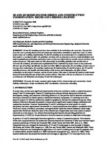
is accompanied through the activities according to the workflow specification. The power of workflow systems is in the richness of the constraints they can enforce: e.g., an activity can be performed only if a certain set of activities have been completed, cannot be closed until a certain condition is satisfied, and so on. Integrating hypertexts with workflows means delivering Web interfaces that permit the execution of activities and embody constraints that drive the navigation of users. We call these applications workflow-driven hypertexts (WFdHT, for short). Figure 1 pictorially contrasts the characteristics of workflow managements systems, of hypertext applications, and of WFdHTs. "Pure" workflow management systems are characterized by a rich set of constraints, do not allow free navigation, and expose only the data needed for accomplishing the workflow objective. "Pure" hypertexts are at the opposite side, because they do not constrain navigation nor establish the accessible information a priori. WFdHTs lay in the middle of the spectrum. Constraints, the degree of navigation freedom, and the amount of displayed information can be tuned to obtain different application flavors.
Contraints
Pure WFMS
WF-driven hypertexts Pure hypertexts Information & navigation richness Figure 1 – Hypertexts vs. workflows
The definition of WFdHT does not cover all the possible workflow systems, leaving out those applications where the enforcement of complex process constraints is the prevalent concern. As an example of what could be considered a complex constraint we mention: complex temporal conditions, workflow exceptions, composite workflows consisting of independent sub-workflows, and so on. However, we claim that many Web applications demand simple workflow capabilities smoothly integrated with navigational interfaces, and are well represented by the concept of WFdHT. The development process that we advocate for WFdHTs is centered on conceptual modeling, a phase in which the application requirements are formalized in a high-level and platform-independent way. The conceptual model of a WFdHT blends three ingredients: o
The process model: it represents the process to be executed, in terms of the activities that compose it, their precedence constraints, and the actors in charge of executing each activity.
o
The data model: it represents the domain objects published and manipulated in the application, and possibly additional data necessary for implementing the application (e.g., data about the users, auditing data, and so on).
o
The hypertext model: it specifies the elements of the hypertextual interfaces for executing the activities, in terms of the pages delivered to the user, the content published in each page, the operations callable from the interface, and the links necessary to enable navigation and operation invocation.
4
Specification And Design Of Workflow-Driven Hypertexts
The process, data, and hypertext models are orthogonal perspectives, which must be integrated into a coherent application design method. In the next sections, we briefly overview the notations used in each individual model, and then show how the process modeling perspective affects the data and the hypertext model. Then, in Section 7 we show how the process model can be transformed into the specification of a hypertext that "realizes" it; such hypertext offers a set of interfaces whereby the actors of the process can execute the required activities, respecting the workflow constraints. 3 Process model Several high-level notations can be used to specify the process model of a workflow application. In the sequel, we will adopt the terminology defined by the Workflow Management Coalition - WFMC [21], which is based on the following concepts: o
Processes, i.e., the description of the supported workflows.
o
Cases, i.e., the process instances created, managed and (eventually) terminated by the application. Cases represent the specific activations of the process.
o
Activities, i.e., the units of works composing a process.
o
Activity instances, i.e., the individual instantiations of an activity within a case.
o
Actors, i.e., the users performing the work.
o
Constraints, i.e., the logical precedence among activities. The WFMC specifications includes a rich set of primitives: sequences of activities, AND-splits (i.e., points where a single thread of control splits into two or more threads, which can proceed autonomously and independently), AND-joins (points where two or more parallel activities converge), OR-splits (points where a single thread of control makes a decision upon which branch to take among multiple alternative workflow branches), OR-joins (points where two or more alternative branches re-converge to a single common thread of control), iterations for repeating the execution of one or more activities, pre- and post-conditions (which represent entry criteria and exit criteria to/from a particular activity, respectively). Applicant
Company: Mgr
Application Request
StartValidation Not valid Valid
Company:Empl
Company:Empl
JobCheck
SecurityCheck
Company:Mgr EndValidation
Figure 2 - Loan application process.
Figure 2 exemplifies a process modelled according to the WFMC specification. The process deals with the validation of a loan request. The process starts with an application request issued by an applicant, which is submitted for validation to a manager of the loan company. The manager may
M. Brambilla, S. Ceri, S. Comai, P. Fraternali, I.Manolescu
5
either reject it (if the application is not valid) and this choice terminates the process, or assign it in parallel to two distinct employees for checking. After both checks are complete, the manager receives the application back and makes the final decision. 4 Data model Data modeling aims at specifying the information assets produced and consumed by the application. Data modeling is traditionally performed with the Entity-Relationship (E-R) language, which is based on the well-known concepts of entities, attributes, and relationshipsb. As an example, Figure 3 shows the E-R schema describing the database of a loan application: it contains the description of different loan categories and loan solutions, and news related to the loan solutions. Solution
Category Name Description
0:N
1:1 Code
Name Description
News 0:N
0:N Date
Text
Figure 3 - Sample data model for a loan application.
5 Hypertext model Hypertext specification aims at expressing the navigable front-end of the application; in the sequel, we adopt the WebML language [6] c, a high-level notation for specifying Web applications developed on top of database content described using the ER model. A WebML schema consists of one or more hypertexts (called site views), expressing the Web interface used to publish or manipulate the data specified in the underlying E-R schema. A site view is a graph of pages to be presented on the Web. Pages enclose content units, representing atomic pieces of information to be published (e.g., indexes listing items from which the user may select a particular object, details of a single object, entry forms, and so on); content units have a selector, which is a predicate identifying the entity instances to be extracted from the underlying database and displayed by the unit. Pages and units can be connected with links to express a variety of navigation effects. Besides content publishing, WebML allows specifying operations, like the filling of a shopping cart or the update of content. Basic data update operations are: the creation, modification and deletion of instances of an entity, or the creation and deletion of instances of a relationship. Operations do not display data and are placed outside of pages; user-defined operations can be specified, such as sending e-mail, login and logout, e-payment, and so on. Figure 4 shows two pages of a simple loan Web site and the WebML specification corresponding to such pages. The leftmost page shows a list of loan categories, displayed as text anchors. The corresponding WebML model presents a Loans page enclosing an index unit named “Categories Index”. When the user selects a category, he is taken to a page displaying data about the selected category and the list of related loan solutions. This is modeled in WebML by a second page ("Solutions page") enclosing a data unit (“Category”), displaying the attributes of the selected loan category, and an index unit (“SolutionsIndex”) displaying the loan solutions of the selected category. b
Data modelling can be alternatively conducted using UML class diagrams. In this paper, we use E/R diagrams, because there is no need of expressing class methods exhibiting complex business logic. c We use WebML as a representative of hypertext modelling languages. Other comparable languages could be used, without prejudice to the illustrated approach.
6
Specification And Design Of Workflow-Driven Hypertexts
Note that the link between the "Categories Index" unit and the "Details" data unit transports as an implicit parameter the identifier of the category to display; this identifier is also associated as a parameter with the incoming link of the "SolutionsIndex" unit and is used to compute the unit's selector ([CategoryToSolution]), which retrieves only the solutions connected by the relationship "CategoryToSolution" to the category visualized in the "Category" data unit. By selecting a specific solution from the index, its details are shown in the same page: this is specified by the "Solution" data unit linked to the "SolutionsIndex" unit. Figure 5 shows an example of WebML hypertext with operations, and its rendition in HTML. The Administrator page encloses an entry unit enabling the user to insert a new piece of news; clicking on the “submit” button activates an operation chain composed by a create operation, generating a novel piece of news, and a connect operation, connecting the piece of news to the currently selected solution. 6 Modelling Workflow-Driven Hypertexts Modeling WFdHTs requires a convergence of concepts from process, data, and hypertext modeling. In particular, the process model affects the data and hypertext models: o
The data model must incorporate user-related and workflow-related meta-data, which enable the specification of access control and activity tracking requirements.
o
The hypertext model must express the boundaries of activities (i.e., where in the application interface an activity can be started and terminated) and the operations necessary to track the execution of the process.
Solutions page
Category Loans page
Solutions Index
Name:
Loans Categories
Educational
° Consumer loans Æ Educational loans ° Saving plans
Description:
° Basic undergr. Æ Basic graduate ° Parents
...
Solution details Basic graduate solution This solution ...
Loans page
Solutions page
Categories Index
Category
SolutionsIndex
Category
Category
Solution [CategoryToSolution] Solution Details
Solution
Figure 4 - Hypertext fragment of a loan application.
M. Brambilla, S. Ceri, S. Comai, P. Fraternali, I.Manolescu
7
Administrator page
Selected solution Solutions page
Name: Basic graduate
Solutions Index
Description:
° Basic undergrad.
...
Æ Basic Graduate ° Parents
News details
° ...
Date: Text: Submit
Solutions page Solutions Index
Administrator page Selected
Solution
Solution
Connect
Create News
NewsToSolution
News
Insert news data
Figure 5 - Hypertext fragment with operations.
6.1 Data model for WFdHTs In the specification of a WFdHT, the data model, which is normally used to describe the domain objects, is extended with user-related and workflow-related data. Figure 6 shows a basic data model encompassing all the main concepts of the WFMC process model. The schema includes entities representing the elements of a process, and relationships expressing the semantic connections of the process elements. Entity Process is associated with entity ActivityType, to represent the classes of activities that can be executed in a process. Both entities describe general data about processes and activities, which need not be replicated for each process/activity instantiation. Entity Case denotes an instance of a process, which has a name, used as a label for communicating with the user, a start time, an end time, and a status, which can be: initiated, active (when at least an activity is started), or completed. Entity ActivityInstance denotes the occurrence of an activity, described by the start time, the end time, and the current status, which can be: inactive, active and completed. Entities User and Group represent the workflow actors, as individual users organized within groups. A user may belong to different groups, and one of such groups is chosen as his default group, to facilitate access control when the user logs in. Activities are "assigned to" user groups: this means that users of that group can perform the activity. Instead, concrete activity instances are "assigned to" individual users, who actually perform them. The schema of Figure 6 makes some simplifications with respect to the full WFMC specification, such as, for example, the omission of sub-activities. However, this basic schema may be enriched with
8
Specification And Design Of Workflow-Driven Hypertexts
further relationships and/or attributes, according to the requirements of the specific workflow application. The user and workflow data model is an extension of the application data model and the designer can specify an arbitrary number of relationships between the application data and the workflow data, which may be required to connect the workflow activities to the data items they use. This connection can be expressed as a relationship (generically called "RelatedTo", as shown in Figure 6), which connects the instances of the application entities with the activity instances where they are used. In this way, it is always possible to deduce from any application object the activity instance(s) where the object is currently in use, and, consequently, the case(s) and the user(s) associated with the activity instance. Workflow Data Model Group
0:N
0:N Assigned To
ActivityType
1:1
Name Description
0:N
0:N
0:N
1:N
Default 1:1
1:1
Process
1:N PartOf
Name Description
Instance-of
Case
Activity Instance
User 0:N
1:1 Assigned To 0:N
Status StartTimeStamp EndTimeStamp
0:N
0:N
RelatedTo
1:1
RelatedTo
0:N
0:N
Entity X
Entity Y
1:N Status PartOf CaseName StartTimeStamp EndTimeStamp
RelatedTo 0:N
Entity Z
Application Data Model Figure 6 - Data model incorporating workflow concepts.
To make the data model more concise, the presence of a relationship between application entities and workflow activities can be specified by tagging the entities for which such relationship holds with a "W" tag (where “W” stands for workflow-related), as shown in Figure 7. Entity X
W
Figure 7 – Graphical shorthand for entities related to a workflow activity.
6.2 Hypertext model for WFdHTs To ease the specification of hypertexts for executing workflows, a few additional primitives are introduced in WebML for updating workflow-related data as a result of activity execution, for accessing the data associated with a specific activity instance, and for expressing the assignment of data objects to the "work queue" of an activity instance. Recording the execution of activities. Updating the workflow-related data as a consequence of the execution of an activity requires ad hoc constructs; the pages/units associated with the execution of an activity must be enclosed between the two workflow-related operations shown in Figure 8: start activity and end activity.
M. Brambilla, S. Ceri, S. Comai, P. Fraternali, I.Manolescu Start Activity
End Activity
ActivityName
ActivityName
9
Figure 8 – Start and end activity operations.
These operations delimit a portion of the hypertext devoted to the execution of an activity and have the side effect of updating the workflow data. Specifically, starting an activity implies creating an activity instance, recording the activity instance activation timestamp, connecting the activity instance to the current case (using relationship PartOf), to the current user (using relationship AssignedTo), and to the proper activity type, and setting the status of the activity instance to "active". Symmetrically, ending an activity implies setting the status of the current activity instance to "completed" and recording the completion timestamp. The start activity operation can also be tagged as the start of the case, when the activity to start is the first one of the entire process; dually, the end activity operation can be tagged as the end of the case, when the activity is the last one of the entire process. At case start, a new case instance is created with status=“running”; when the case ends, its status is set to “terminated”. Figure 9 shows the graphic notation for case start / end. The circles in the upper part of the icon denote that the operation starts or ends the case. Start Activity
End Activity
ActivityName
ActivityName
Figure 9 – Start and end case notations.
Accessing the data associated with an activity instance. For retrieving the data objects related to the instances of a particular activity, workflow-aware content units can be used. These units are like the regular WebML content unit but are tagged with a "W" symbol denoting a simplified syntax for their selector, which shortens the expression of predicates involving both application data and workflow data. For example, Figure 10 shows a workflow-aware index unit that retrieves all the instances of entity Document, related to an instance of activity "Translation" relevant to the user passed as a parameter to the unit. The selector [ActivityType = "Translation", User = CurrentUser] is written as if the ActivityType and User attributes were defined locally in the Document entity, even if these attributes belong to the workflow-related entities of the data schema. Specifically, the selector of Figure 10 is equivalent to the following (more verbose) expression, which exploits the relationships between the entity Document and the workflow-related entities illustrated in Figure 6: [DocumentToActivityInstance.ActivityInstanceToActivityType.name="Translation"], [DocumentToActivityInstance.ActivityInstanceToUser.OID= CurrentUser]
10
Specification And Design Of Workflow-Driven Hypertexts
Current User
Relevant documents W
Document [ActivityType="Translation"] [User=CurrentUser]
Figure 10 – Workflow-aware content unit notation.
Assigning data to activity instances. The assign operation is a WebML operation unit conceived for connecting an application object (or a set of objects) to an activity instance, identified by a particular activity type and case. Optionally, the assign unit can specify a user, who should take charge of processing the object as requested by the activity instance. Figure 11 shows the graphical representation of the assign operation, which assigns the document passed in input by the link to the activity called "Translation", for the current case and for the currently logged user. The assign unit permits the specification of a "data connection" between activities: when activity X produces some item I, which is consumed by an activity Y in the same case, the item I can be "passed" from activity X to activity Y by placing a suitable assign operation in the hypertext pages associated with activity X. DocID
Assign A
Document [Activity="Translation"] [User=CurrentUser] [Case=CurrentCase]
Figure 11 - Graphical notation of the assign operation.
Conditional links. The navigation of a WFdHT may need to be conditioned by the status of activities, to reflect the constraints imposed by the workflow. Conditional navigation can be expressed in WebML by means of two dedicated operations (the "if" and "switch" operations, illustrated in Figure 12), performing the necessary status tests and deciding the destination of a navigable link. result parameter 1
Switch
... parameter N
[1] [2] [3]
OK
parameter 1
result
... parameter N
OK
If
[true]
OK
[false] OK
result OK
KO
KO
result OK
Figure 12 - Switch and if units
Both the switch and the "if" units receive in input a set of parameters and use these parameters to evaluate an expression. If the evaluation of the expression fails, a KO-link is followed, typically
M. Brambilla, S. Ceri, S. Comai, P. Fraternali, I.Manolescu
11
leading to an error paged. If the evaluation of the expression succeeds, one of the output OK-link is followed depending on the result of the evaluation. The "if" unit evaluates a Boolean expression and provides two output OK-links, one to be followed if the condition is true, and one in case the condition is false. The "switch" unit evaluates a constant expression and presents a set of output links, one for each case to be considered in the switch statement, plus one for the default case. A guard-condition on the result of the expression is specified on each non-default output link to decide which link to follow (in the example in Figure 12 three cases are considered: the result of the expression may be 1, 2, or 3). Note that "if" and "switch" units introduce a degree of flexibility in navigation control, that is, in the decision of what to do in response to a user-generated navigation event. Such control is normally represented by links in the hypertext diagram, which show which page to display, or which operations to execute, after a user's click. Without "if" and "switch" units, navigation diagrams assume that the link destination is known at design time; conversely, the introduction of "if" and "switch" units allows a form of dynamic control of navigation, because the destination of a link is determined at runtime by evaluating a logical condition. 7 Mapping processes to hypertexts So far, we have discussed the individual modelling perspectives of a WFdHT, and the ways in which the data model and the hypertext model can incorporate workflow-specific notions. We now discuss how the three modelling perspectives interact in the design process of a WFdHT. Our approach considers the process model a higher-level specification, from which the designer can produce a hypertext that "realizes" the process model. Such hypertext exploits the data schema representing the generic workflow concepts, exemplified in Figure 6. Given the process model dictating the flow of activities to be performed by a set of actors, a hypertext that realizes it is obtained in the following steps: o
Design in the large: the site views to be delivered to the different kinds of actors involved in the workflow and the activities of each site view are identified.
o
Design in the small: the hypertextual interfaces of the individual activities are designed in such a way that the constraints among the activities in each site view are respected.
7.1 Design in the large A site view is a set of linked pages delivered to a specific group of users. Similarly, workflow processes involve different classes of actors in charge of different activities. Therefore, it seems natural that the site views associated with the various groups are used to cluster all the pages that implement the activities of a specific class of workflow actors. As an example, consider a generic workflow like the one in Figure 13, which describes the activities performed by three classes of users (Group1, Group2, and Group3), and the precedence of these activities.
d
In the examples of the following sections we will not explicit KO-links. By default, in case of operation failure the last page displayed to the user is re-displayed.
12
Specification And Design Of Workflow-Driven Hypertexts
Group1
Group2
Group3
Activity1
Activity2 Activity3
Activity4 Activity5
Figure 13 - General workflow.
A workflow involving N user groups can be rewritten as a set of N workflows, each representing the activities of a single group. For example, the process described in Figure 13 can be split into the three sub-workflows shown in Figure 14. The activities of each sub-workflow are then implemented inside the site view of the corresponding group. Note that constraints between the activities in different sub-workflows must be enforced. Consider, for example, Activity5: it must follow both Activity2 and Activity4, which are performed by different users and will be implemented in different site views. These precedence constraints must be specified in the site view of Group 1 by means of suitable hypertext design patterns, produced during design in the small.
Group1
Activity1 Act.2 and Act.4 completed
Activity5
Group2
Act.1 completed
Activity3
Group3
Act.1 completed
Activity2
Activity4
Figure 14 – Sub-workflows for groups 1, 2 and 3.
M. Brambilla, S. Ceri, S. Comai, P. Fraternali, I.Manolescu
13
7.2 Design in the small Workflow activities are realized in the hypertext model by suitable configurations of pages and units representing the interfaces for executing them, enclosed between start / end activity operations. Workflow constraints must be turned into data passing and navigation constraints among the pages of the activities, ensuring that the data shown by the application and user navigation respect the constraints described by the process specification. In this section we describe how the precedence and synchronization constraints between the activities can be expressed in the hypertext model. In this paper we treat only some of the WFMC precedence constraints, which include sequences of activities, pre- and post-conditions, AND-splits, AND-joins, and OR-splits. The simplest WFMC constraint is the sequence: given two activities A and B, the constraint expressing that activity B must be performed after activity A can be realised in an hypertext specification as illustrated in Figure 15. Figure 15.a shows a first realisation based on an explicit link going out of the page implementing the interface of Activity Ae: navigating the link terminates activity A, starts activity B and opens the page for executing B; Figure 15.b shows an alternative realization based on data coordination: when the link outgoing the page of Activity A is navigated, it assigns some data to activity B; the page of activity B can be accessed at any time, but activity B can be performed only when some data assigned from activity A is available in a workflow-aware content unit, like the index unit shown in Figure 15.b. If no data has been assigned to activity B, the index remains empty and thus the link for stating activity B cannot be navigated. a)
pages/ units
...
Start Activity
Activity A pages/units
End Activity
... A
A
Start Activity
Activity B pages/units
End Activity
...
... B
b)
pages/ units
B Activity A pages/units
Start Activity
...
... A
...
Assign
Applic. Index
Start Activity
Activity B pages/units
B
pages/ units
... A
End Activity
pages/ units
...
...
W Application [Activity="B"]
End Activity
A
Application [Activity="B""] [Case=CurrentCase]
Validation choice pages/ units
pages/ units
B
Figure 15 – Hypertext realization of the sequence
Pre-conditions, i.e., conditions that have to be true in order to start an activity, can be expressed through if units. Figure 16.a shows a first realization, where the link outgoing from the page of Activity A terminates this activity, checks a condition (the pre-condition), if this is true starts Activity B, and opens the page for executing Activity B. If the condition is false the user will be led to another page, which in this example has not been represented. Activity B can be therefore performed only if e
The following examples use generic rectangles to denote the implementation of the interface of an activity. In reality, they consist of pages/units, and links to operations necessary for performing the activity.
14
Specification And Design Of Workflow-Driven Hypertexts
the pre-condition specified by the "if" unit is true. Figure 16.b shows a different realization, which extends the case already seen in Figure 15.b: some data are assigned to Activity B only if a condition is satisfied; since activity B will be performed according to the availability of such data, the precondition is enforced. a)
pages/ units
Start Activity
...
Activity A pages/units
End Activity
If
[true]
... [false]
A
A
Start Activity
Activity B pages/units
pages/ units
End Activity
...
... B
b)
pages/ units
...
B
Activity A pages/units
Start Activity
[false] If
[true]
...
Applic. Index
Start Activity
A
pages/ units
End Activity
...
...
W Application [Activity="B"]
Activity B pages/units
pages/ units
...
Application [Activity="B""] [Case=CurrentCase]
Validation choice
...
End Activity
A
A
pages/ units
Assign
B
B
Figure 16 – Realization of pre-conditions
Post-conditions, i.e., conditions that have to be true in order to declare an activity completed, must be tested before terminating an activity; this can be done using a hypertext like the one shown in Figure 17: when the link exiting the page of Activity A is navigated a condition for terminating the activity is checked: if this is true the activity can be terminated, otherwise the user is led back to the pages implementing the activity, to complete the work.
pages/ units
...
Start Activity
Activity A pages/units
[false] If
[true]
End Activity
...
... A
pages/ units
A
Figure 17 – Realization of post-conditions
AND-splits and AND-joins can be represented as shown in Figure 18: activities A and B can be performed in any order; when both activities have been terminated activity C can start. In the realization in Figure 18.a, from the initial page the user may either choose activity A or activity B; after termination of activity A (B) a test condition checks if activity B (A) has not been executed yet. If this condition is true a navigation link leads the user to the starting point of activity B (A), so that also activity B be executed; instead, if both activities have been completed the next activity C can be started. The realization in Figure 18.b specifies the same constraint using data coordination. Both activities A and B can be started. When activity A ends and activity B has been already performed, then some data are assigned
M. Brambilla, S. Ceri, S. Comai, P. Fraternali, I.Manolescu
15
to activity C; analogously, when activity B ends and A has been already done. Activity C is therefore enabled only when both activities have been completed. a)
Activity A pages/units
Start Activity
End Activity
If [false]
... [true]
Page
A
A
...
Start Activity
[true]
Activity B pages/units
End Activity
C
If [false]
... B
b)
pages/ units
...
B [false]
Activity A pages/units
Start Activity
If
[true]
Assign
...
...
A
Assign
End Activity
If
...
Application [Activity="C""] [Case=CurrentCase]
Validation choice Applic. Index
Start Activity
Activity C pages/units
Application [Activity="C"]
B
pages/ units
End Activity
...
...
W
pages/ units
...
A
B
...
...
Application [Activity="C""] [Case=CurrentCase]
[true]
pages/ units
pages/ units
[false]
Activity B pages/units
Start Activity
End Activity
A
A
pages/ units
pages/ units
Start Activity
C
C
Figure 18 – Realization of AND-split and AND-join
As a final example, Figure 19 represents the realization of an OR-split, where the branch to be followed is decided according to a data-dependent criterion: when the navigation link outgoing from the initial page/unit represented on the left hand side of the example is followed, the condition of a switch unit is checked, which redirects the user to the starting point of activity A, B or C, respectively: only one of these three activities is started. Start Activity
Activity A pages/units
End Activity
...
... pages/ units
...
[1] Switch [2]
A Start Activity
Activity B pages/units
A End Activity
B Start Activity
Activity C pages/units
B End Activity
pages/ units
...
... C
pages/ units
...
...
[3]
pages/ units
C
16
Specification And Design Of Workflow-Driven Hypertexts Figure 19 – Realization of OR-split with outcome automatically chosen by the system.
8 Example of WFdHTs The following example will show the proposed approach at work in the specification and design of a small-scale example. Consider a simplified workflow for managing the application for a loan. The Web site, beside publishing pages containing information about the solutions provided by the company, allows a user to apply for a loan by filling some forms. Once the forms have been filled the company performs some checks and returns a response to the user who will be then contacted by an advisor for the final contract. Figure 2 details the process model describing the flow of the activities supported by the Web site: first the applicant makes a request; then the company starts the validation process, checking if the request is valid or not: if it is not valid the process stops, otherwise an application reference number is supplied by e-mail to the applicant, which allows him to see the data of his request from the Web site, and some checks are performed in parallel by the company. According to the results of such checks the company takes a final decision and ends the validation process. We will suppose that managers perform the start and the end validation activities, and that employees perform checks. Three site views will be designed, one for each group of users: applicants, company's managers, and company's employees. For each group the sub-workflows of this process can be immediately obtained as seen in Section 7. The data schema for this example is very simple: in particular, it will include an entity (we will call it Application) containing the application data inserted by a user and some additional information added by the company during the validation/check process. We suppose that the Application entity is related to the workflow data. Figure 20, Figure 21, and Figure 22 show a possible site view for the applicant, the manager and employee groups, respectively. The applicant (Figure 20) may start the process from the home page. The other pages of the site are omitted in this example, but they should be specified in this site view. Since the request for an application starts the whole process, the start activity operation starts also the case. The applicant may then fill a form with his personal data and all the data needed for granting a loan. A new application containing the data inserted by the user is then created, and assigned to the start validation activity. The applications assigned to this activity will be then retrieved by a workflow-related index unit in the manager’s site view. At this point the activity ends and the user is led to the home page again. Applicant Site View ApplicationRequest page
Home page Start Activity
Data Entry
CreateData
Assign
End Activity
A
Request
Application
Application [Activity="StartValidation"] [Case=CurrentCase]
Figure 20 – Applicant site view.
Request
M. Brambilla, S. Ceri, S. Comai, P. Fraternali, I.Manolescu
17
The manager (Figure 21) may start two activities: he may start the validation of a new application or end a validation process of an application already checked by the company’s employees. From the home page two links allow him to reach two pages, where the lists of the applications for which the validation process has to start or to end are shown by means of workflow-related index units. These units retrieve all the applications which have been assigned to the corresponding activities and which have not been processed yet. Once an application has been chosen, the corresponding activity starts. In the start validation activity the manager may either stop the process if the application is not valid (e.g., it does not contain meaningful or real data) or fill in a form to continue the process. In the former case both the activity and the case are ended. In the latter case some new data are added to the application using a “modify unit”, an e-mail is sent to the user providing an application reference number, the application is assigned to the subsequent checking activities and, finally, the activity is ended. In the end validation activity the manager fills in and submits a form; the submission updates the current application, sends an e-mail to the user, and terminates the activity and also the current case. The employees (Figure 22) may work on the two check activities: the first one checks that the applicant has a solid job, the second one that he has a clear record with his bank and the justice department. For both activities, the lists of the applications to be validated are retrieved by means of workflow-related index units. Then, selecting an entry from the index unit starts the respective activity. Both activities are similar, so we describe only one of them: the employee performs the required checks and fills in a form, which updates the current data of the application. If all the checks have been performed on the application (i.e., also all the other check activities have been completed for the current application), the application is ready to be assigned to the end validation activity. Notice that the if unit expresses the pre-condition for an AND-join, to decide if the application has to be passed or not to the next activity, which joins two process branches when both the checking activities have been completed. 9 Implementation and experience The modelling approach discussed in this paper has been experimented in the context of a real-world CASE tool, called WebRatio [20], which supports the model-driven development of "traditional" Web applications. WebRatio has an extensible architecture, where new modelling primitives can be easily plugged into the design environment and code generators, by wrapping the code that implements them using XML and XSL. The data and hypertext model primitives discussed in Section 6 have been implemented by extending the default data schema of WebRatio applications to incorporate the workflow-related entities and relationships, and by implementing a package of custom content units and operations and the associated code generator. The transformation of the process model expressed using the WFMC notation into the hypertext that realizes it, described in Section 7, has been performed manually. In the future, an XSL style sheet will be written to automate the production of the site views and generate the stubs of the pages for performing the activities, and the configuration of start/end operations, assign operations, and conditional links necessary to connect them. This function will ease the design process, by making most of the ad-hoc WebML syntax for expressing workflow-related aspects automatically generated by the system from higher-level specifications. When the design of the workflow-driven hypertext is complete, the WebRatio code generator transforms it into a J2EE or Microsoft .NET Web application, which includes the interfaces for executing the activities according to the workflow specification. Activities are synchronized using conditional navigation (implemented as server-side scripting instructions for dynamically calculating
18
Specification And Design Of Workflow-Driven Hypertexts
the destination of links) based on tests on the workflow-related data; no ad hoc controller has been developed, but the standard controller of the WebRatio MVC 2 architecture proved sufficient. Manager Site View Start Validation page
Start Validation choice Applic. Index
choice
Details
Start Activity
Data Entry
ModifyData
choice
W
Application [Activity="StartValidation"]
StartValidation
Application
Application NotValid SendMail End Activity
StartValidation Home page End Activity
StartValidation
Assign A
Application [Activity="JobCheck", "SecurityCheck"] [Case=CurrentCase]
End Activity
Applic. Index
choice
EndValidation
End Validation page
End Validation choice Start Activity
choice
Details
Data Entry
ModifyData
W
EndValidation Application [Activity="EndValidation"]
Application
Application
Figure 21 – Manager site view.
SendMail
M. Brambilla, S. Ceri, S. Comai, P. Fraternali, I.Manolescu
19
Employee Site View JobCheck page
JobCheck choice Applic. Index
choice
Start Activity
choice
Details
Data Entry
ModifyData
W
Application [Activity="JobCheck"]
JobCheck
Application
Application SecurityCheck Done
[false]
[true]
Home page End Activity
Assign A
JobCheck
Security Check page
SecurityCheck choice Applic. Index
Application [Activity="EndValidation"] [Case=CurrentCase]
choice
Start Activity
choice
Details
Data Entry
ModifyData
W
Application [Activity="Security Check"]
Security Check
Application
Application JobCheckDone
[false]
End Activity
[true]
Assign A
Security Application Check [Activity="EndValidation"] [Case=CurrentCase]
Figure 22 – Employee site view.
The ideas discussed in the paper have been benchmarked in the development of a real workflowdriven Web application (www.aceradvantage.com). The application deals with the process of requesting, checking, and activating a warranty extension for laptops and personal computers, which requires the execution of a workflow spanning several individuals and business units of the service provider. The application is a perfect representative of the concept of WFDHT, because it requires the use of hypertextual interfaces, to which the customer is accustomed, the delivery of data (e.g., the warranty contracts) and the enforcement of process constraints. The application was successfully delivered in a very short time (five weeks), and has been generated automatically from a conceptual model produced following the steps discussed in Section 7. Developers, who were previously trained in hypertext modelling, understood quickly the interplay of workflow and interface requirements, and appreciated the separation of concerns and clear "design workflow" induced by the proposed approach. The benefits of a formal design method became apparent when a major variation of the workflow intervened, to serve the specific requirements of new countries. The process model was redesigned, the hypertext model was updated accordingly, and the application was re-generated for the new countries.
20
Specification And Design Of Workflow-Driven Hypertexts
10 Related work WebML [6] is one of a family of proposals for the model-driven development of Web sites, which includes also other approaches, e.g., Araneus [2], Strudel [11], OO-HDM [18], W2000 [4], and OOHMETHOD [12]. Among these approaches only for Araneus the authors tried to extend the proposed framework with a workflow conceptual model and a workflow management system, cooperating with the other system tools [15]. Also many commercial enterprise toolsuite, such as IBM MQSeries Workflow [13] and Oracle Workflow 11i [17] implement complete workflow management systems, based on workflow engines. These tools aim at integrating different enterprise applications, often developed by the same vendor. In this scenario, application and workflow Web publishing consists in re-building the existing application for the Web context (e.g., as Java applets) and applying workflow rules for their cooperation. Differently from Araneus and the currently available commercial toolsuites, our proposal does not provide a workflow engine. We offer a methodology and a high-level modelling framework for a homogeneous description of a Web application with workflow constraints, helping the designer conceptualize and organise an application involving roles, and workflow-style paradigms. Our approach is suitable for lightweight applications, which are very common on the Web, and is based on simple concepts, whose code can be automatically generated. 11 Conclusions In this paper we have presented workflow-driven hypertexts, as an emerging class of Web applications that demand proper development methods, integrating concepts from "traditional" process, data, and hypertext modelling. We have proposed a structured development approach where the process model is transformed into a hypertext model that realizes it; such hypertext incorporates site views and pages assisting the different workflow actors in the correct execution of the activities assigned to them; this approach requires minimal extensions to the current Web modelling languages, no extension to the data modelling notations already familiar to developers, and is easily implementable in the context of state-of-the-practice CASE tools. Our future work will proceed along three directions: more complex process modelling features will be considered, to widen the spectrum of workflows to which the proposed approach can be applied; further experiments will be conducted with CASE tools, to better automate the derivation of hypertext from process models; finally, verification rules for keeping the hypertext model aligned with the process model during evolutive maintenance will be studied and implemented in the CASE tool. Acknowledgements We wish to thank Marco Caimi, Alberto Allara, Andrea Maurino and Maristella Matera for helpful comments and suggestions about the integration of workflows in WebML specifications. References 1. 2. 3.
Baumeister, H., Koch, N. and Mandel, L., Towards a UML Extension for Hypermedia Design. in UML 1999, (1999), 614-629. Paolo Atzeni, Giansalvatore Mecca, Paolo Merialdo: Design and Maintenance of Data-Intensive Web Sites. EDBT 1998: 436-450. Arcstyler Homepage: http://industry.java.sun.com/solutions/products/by_product/0,2348,all-26517,00.html
M. Brambilla, S. Ceri, S. Comai, P. Fraternali, I.Manolescu
4. 5. 6. 7. 8. 9. 10. 11. 12. 13. 14. 15. 16. 17. 18. 19. 20. 21.
21
Luciano Baresi, Franca Garzotto, Paolo Paolini: From Web Sites to Web Applications: New Issues for Conceptual Modeling. ER Workshops 2000: 89-100. Qiming Chen, Umeshwar Dayal, Meichun Hsu: Conceptual Modeling for Collaborative Ebusiness Processes. ER 2001: 1-16. Stefano Ceri, Piero Fraternali, Aldo Bongio: Web Modeling Language (WebML): a modeling language for designing Web sites. WWW9/Computer Networks 33(1-6): 137-157 (2000) Stefano Ceri, Piero Fraternali, Stefano Paraboschi: Data-Driven, One-To-One Web Site Generation for Data-Intensive Applications. VLDB 1999: 615-626. Stefano Ceri, Piero Fraternali, Aldo Bongio, Marco Brambilla, Sara Comai, Maristella Matera: Designing Data-Intensive Web Applications, Morgan-Kaufmann, December 2002. Coldfusion Homepage: http://www.macromedia.com/software/coldfusion/ J. Conallen: Building Web Applications with UML. Addison Wesley (Object Technology Series), 2000. Mary F. Fernandez, Daniela Florescu, Jaewoo Kang, Alon Y. Levy, Dan Suciu: Catching the Boat with Strudel: Experiences with a Web-Site Management System. SIGMOD 1998: 414-425. Jaime Gómez, Cristina Cachero, Oscar Pastor: Conceptual Modeling of Device-Independent Web Applications. IEEE MultiMedia 8(2): 26-39 (2001). IBM MQSeries Workflow Homepage: http://www.ibm.com/software/ts/mqseries/workflow/v332/ Jdeveloper Homepage: http://industry.java.sun.com/solutions/products/by_product/0,2348,all3445-99,00.html Giansalvatore Mecca, Paolo Merialdo, Paolo Atzeni, Valter Crescenzi: The (Short) Araneus Guide to Web-Site Development. WebDB (Informal Proceedings) 1999: 13-18. Microsoft .NET Homepage: http://www.microsoft.com/net/ Oracle Workflow 11i: http://www.oracle.com/appsnet/technology/products/docs/workflow.html D.Schwabe, G.Rossi: An Object Oriented Approach to Web Applications Design. TAPOS 4(4): (1998). The WebML Project Homepage: http://www.webml.org. WebRatio Homepage: http://www.webratio.com/ Workflow Management Coalition Homepage: http://www.wfmc.org