(B) This is a contract-based testing that requires the definition and testing of pre and .... subtyping [11] or contract-based programming must be followed, i.e., the ...
Specification-based Testing of User Interfaces Ana C. R. Paiva1, João C. P. Faria1,2, Raul F. A. M. Vidal1 1
Faculdade de Engenharia da Universidade do Porto / 2INESC Porto Rua Dr. Roberto Frias, s/n 4200-465 Porto, PORTUGAL
{apaiva, jpf, rmvidal}@fe.up.pt
Abstract. It is proposed an approach to integrate formal methods in the software development process, with an emphasis on the user interface development. The approach covers the specification by means of formal models, early model animation and validation, construction and conformity testing of the user interface implementation with respect to the specification. These conformity tests are described in detail through a state transition model with an abstraction function mapping concrete (implementation) to abstract (specification) states and operations. In order to illustrate the approach, it is presented a simple login/password dialog specification in VDM++, using a reusable control specification library, with a straightforward translation to Java or C#.
1 Introduction Our society is becoming more and more dependent on software systems. They are present in virtually all parts of modern society: airplanes and cars have computer boards, we do electronically payments, our identity information is registered on databases, we do shopping on the Internet, and so on. This growing implantation of software systems turns us more dependent on their functioning without errors. The correct functioning depends on the exact, unambiguous and complete capture of the customer requirements. It is well known that problems resulting from a misunderstanding of the customer requirements are the most costly to correct, and so there is a need to validate requirements as early as possible with the customer. Formal Methods are "mathematically based techniques for describing system properties" [17]. They can be seen as the applied mathematics of software engineering, providing the notations, theories, models and analytical techniques that can be used to control and analyze software designs. Formal Methods can be helpful to increase confidence in the correctness of software by proof, refinement and testing (both at the specification and at the implementation levels) [9]. Proof, sometimes called formal verification, involves a rigorous demonstration (usually involving deductive logic) that an implementation matches its specification. Refinement is the development of implementations that are correct by construction (a specification is rigorously transformed to derive an efficient implementation). An introduction to the subject can be found in [15], [3]. Testing at the specification level involves executing (animating) the
specification to verify (i.e. detect internal inconsistencies and problems) and validate (i.e., assure that customer requirements are correctly captured) the specification. Testing at the implementation level involves executing an implementation with some input and comparing the actual results to the ones expected. In the case of specificationbased testing, the results expected are obtained from the specification, thus reducing the effort required to prepare them. Nevertheless, the use of formal methods in the industry is still quite limited. Some of the reasons for this difficulty are: • Limited tool support: Existing tools usually cover only specific tasks and aspects, and the integration of different tools is difficult due to different notational rules. • Complexity and unfamiliarity with formal notations: Formal notations are based on simple mathematical concepts, but some notations used may seem unfriendly to software engineers. • Incomplete life-cycle coverage: There is a lack of models and notations that support all the activities of software development (specification, implementation, verification and validation). • Limited application of Formal Methods to the development of graphical user interfaces (GUI): Nowadays, a considerable part of the time spent in application development is consumed with the user interface. Formal specification of user interfaces is important to find errors and inconsistencies during initial phases of development and to prove desired properties. Examples of these properties are: absence of deadlock, predictability of a command, ability to reinitiate, availability of a command, succession of commands, exclusion of commands, bound of state variable and integrity constraints [13]. In spite of investigation about Formal Methods applied to user interfaces, this area is not yet a common area of application. The approach we propose gives a contribute to encourage integration of formal methods in software development process since it supports all phases of software development process and supports the formal specification of user interfaces aspects that are important to assure its correct functioning. The rest of the paper is organized as follows: sections 2 and 3 describe architectural and process issues of the approach. Conformity testing is explained in more detail in section 4. Section 5 presents a specification of a login/password dialog in VDM++ and shows how to apply conformity tests on it. Finally, section 6 summarizes the results achieved.
2 Architectural Issues The ultimate goal of our approach is to help the integration of formal methods in the software development process. To reach that goal the approach intents are: • allow the specification of enterprise applications at a high level of abstraction, without concerns about implementation and platform details, by means of formal models describing both the business logic (business entities and transactions) and
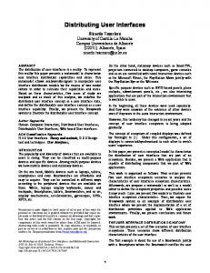
the user interface logic (user interface structure and behaviour, but not user interface style and layout); • allow the execution (animation) of the formal models in early stages of the development process, combined with a non-formal definition of the user interface style and layout, for early model testing and validation of requirements with the customer; • allow, in future, the translation of the specification into a target implementation language in an automatic, manual or semi-automatic way; • support the automatic testing of conformity of the implementation with respect to the specification to assure a correct application and user interface functioning. Fig.1 presents an architectural overview of the approach proposed, showing the main artefacts (or modules) produced during the software development process, at different levels of abstraction (specification and implementation) and layers (database, business logic and user interface layers), as well as the relationships between them. S P E C I F I C A T I O N
I M P L E M E N T A T I O N
Business Logic (BL)
DB
User Interface Logic
Function Call
Business Logic
Result
User Interface Logic
Interpreted action
Result
User Interface Style and Layout
Uninterpreted Action
Visualization
User Interface
Lege nd: Refinement
Message Flow
Testing
Fig. 1. Architectural overview of the approach proposed.
To achieve a good compromise between high level of abstraction of the specification and ease of validation and implementation, a similar architecture is followed at the different levels of abstraction (specification and implementation). Both levels are defined in terms of similar layers (business logic and user interface) and building blocks (classes, event-handlers, user interface widgets, etc.). At the implementation level, there is a separation between the business logic layer (responsible to implement business transactions) and the database layer (responsible to store information about business entities). At the specification level, we are not concerned with persistency issues, and the business layer includes the in memory representation of the system state (information about business entities). Classes that form the building blocks of the business logic layer capture the state of the business entities and the transactions on those entities.
The user interface layer is divided in two sub-layers: • User interface logic: This sub-layer is concerned with describing structure (intervening widgets) and behaviour of the user interface (event-action triggers, validations, maintenance of derived data, enabling/disabling interactive objects, navigation between dialogs/windows, etc.), but not with style and layout issues. This sub-layer communicates with the business logic layer and is defined in both levels (specification and the implementation). • User interface style and layout: This sub-layer is concerned with presentation aspects like disposition of interactive objects on display, colours, size and other “physical” properties. It is also concerned with capturing "raw" (uninterpreted) user actions and translating them into interpreted actions that are propagated to the user interface logic sub-layer. This sub-layer is defined only at the implementation level, but in such a way that it can be used in connection with the user interface logic specification. The separation of the logical aspects of the user interface (structure and behaviour) from its "physical" aspects (style and layout) is fundamental to the effective application of formal methods in the development of user interfaces. The user interface should be defined by the composition of reusable interactors 1 [5] (or widgets or controls), capable of both input and output, and that encapsulate state that is perceivable to the user in the form of a rendering. As such, an interactor spans the two sub-layers above defined (structure and behaviour, and style and layout). Interactors are defined as classes with active properties, events and possibly other instance variables and methods (or operations). An active property is defined as a combination of an instance variable, get and set methods and an event that is raised when its value is changed. The behaviour of interactors can be extended and combined by subclassing, by event-handler addition or by using reusable behaviour elements (such as range validators) that take care of event handling. To ease the mapping between the two levels of abstraction, interactors should also be defined at the specification level, as abstract interactors, without concern about style, layout and platform specific aspects. At the specification level, pre and post-conditions are included to prescribe behaviour. An example can be seen in the appendix. The connection between elements at different levels of abstraction enables: • the execution (animation) of the specification, in combination with the non-formal definition of the user interface style and layout for early model testing and requirements validation; • the translation of the user interface logic specification into a target implementation language, reusing existing widgets or controls (this is an area for future work); • the automatic testing of conformity of the implementation with respect to the specification to assure a correct application and user interface functioning, as will be explained in more detail in section 4.
1
User-interfaces can be defined by a system of objects that communicate with the user. These objects are called interactors.
3
Process issues
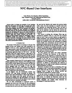
Figure 2 summarizes the sequencing of activities (rounded rectangles) to be performed during the whole software development process and the artefacts produced (rectangles) and used in each activity, emphasizing specification-based testing activities. The process starts with specification activities (activities 1 and 2) and ends with testing in the deployment environment (activity 12).
Specification
User Interface Design
1. Specification of business logic
Business logic specification
2. Specification of user interface logic
User interface logic specification
3. Automatic generation
Default prototype
4. Design user interface
User interface style and layout module
5. Integration of specification and user interface design
Model testing package
Integration and Model Testing (...)
6. Model testing FAIL
Database schema OK
Business logic implementation
7. Generate and enhance business logic implementation and database schema Implementation
User interface style and layout (enhanced)
8. Generate and enhance user interface implementation
User interface logic implementation
9. Integrate Conformity testing package
10. Conformity testing (...) FAIL OK Integration and Implementation Testing
11. Build deployment package
Deployment package
Legend:
12. Final testing
Data/object flow
(...)
Control flow
FAIL OK
•
Activity Artefact
Fig. 2. Activity diagram summarizing the sequencing of activities to be performed during the software development process and the artefacts produced and used in each activity.
The specification activities produce business and user interface logic that gather statements describing the structural and behaviour aspects of the product to be delivered to the customer. Testing usually involves constructing a suite of test cases that should cover a large number of possible situations. Specification-based testing, also known as black-box tests, uses a (formal) specification for determining appropriate inputs and expected outputs. There are two kinds of specification-based testing activities that occur at different points of the software process: activity 6 (model testing) validates ("Are we building the right product?") the specification in the presence of the customer and assures that the requirements specified meet customer’s intent; conformity testing (activity 10) runs a test suite comparing results obtained from implementation and specification levels. These tests are only necessary when manual implementation is used. These testing activities are preceded by integration activities when artefacts are linked together. Non-specification based tests are also needed, e.g., performance tests executed in the deployment environment (activity 12). Activities 3, 7 and 8 can produce artefacts through a refinement process with more or less programmer intervention. The general refinement process between specifications and implementation is a well-studied subject, see for example [15] and [3]. Referring to the user interface generation from interface model, several model-based environments/methods have been constructed. Examples of these environments/methods are: [12] (where a user interface is constructed from a data model), Mecano project [1], FUSE system [8], TRIDENT [7], MASTERMIND [16] and TADEUS [6]. Integration activities are the ones responsible for establishing a relation between specification and implementation levels and provide an environment for early model validation and conformity testing.
4 Conformity Testing The purpose of conformity testing is to automatically check, at run time, that the implementation obeys the specification. In this section, we use a state transition model to represent conformity tests (fig. 3) and discuss different ways of performing them (table 1). To describe conformity tests, we assume the following execution model (both at the specification and implementation level): • The system behaviour is described by transitions between states (including user interface and database state) caused by operations executed in response to user actions or events. • The operations effect may be described as a function F from initial state S1 and possible input arguments FArgs to final state S2 and possible outputs FOut. • The outputs produced can be a message or sequence of messages sent to the user. • The system state (namely state at the user interface logic layer) may be or not observable by the user. A specification can describe behaviour of the user interface,
from the user perspective, by making internal state observable or by sending appropriate output messages to the user. To perform conformity testing automatically, we need to define an abstraction function from the implementation to the specification levels comprising two mappings [19]: • A mapping (R) from the state variables of the implementation to the state variables of the specification, which describes how the abstract states of the specification are represented in the implementation [2]. One implementation is adequate if it can represent all the states that could be represented by the abstract specification. Since the implementation is more detailed, multiple concrete states (at the implementation level) may correspond to the same abstract state (at the specification level). • A mapping (T) from sequences of interface operations at the implementation level to sequences of interface operations at the specification level. Given these two maps, it is possible to perform the elementary tests illustrated in fig. 3 on every state transition. Inv I’
II’
Pre
III’
CS1 IMPLEMENTATION
Pos
VIII’
Inv
CS2
CF CFRes
CFArgs
R
R
R Pos
R SFArgs
T
Inv
SS2
IV
VI
SFRes
SPECIFICATION
=? =? SFResA
SF
SS1
I
Inv II
Pre
III
Pos
VII
V SS2A
VIII
Inv
Fig. 3. Conformity tests model.
Assume that we start at a concrete state CS1 when we apply concrete function CF. In consequence, at the specification level, we start at SS1, that corresponds to CS1 (SS1=R(CS1)), over which it is applied the specification function SF (equivalent of CF). In fact, only a subset of the elementary tests shown in fig. 3 need to be performed in each situation. Table 1 summarizes different ways of performing conformity tests and shows the elementary tests to be performed in each situation.
Table 1. Different ways of performing conformity testing. Specification Specification with obwith output servable state
Execute specification operations
Elementary tests to be performed
A
Yes
Yes or No
Yes
Test initial state invariant (I), pre-condition (II), compare outputs (V) (if present) and final states (VII).
B
Yes
Yes or No
No
Test initial state invariant (I), pre-condition (II), post-condition (IV) and, optionally, final state invariant (VI) at the specification level.
C
Yes
Yes or No
No
Test initial state invariant (I’), pre-condition (II’), post-condition (III’) and, optionally, final state invariant (VIII’) at the implementation level.
D
No
Yes
Yes
Compare outputs (V).
Notes: (A) This is a comparison-based testing that requires the definition in executable form and the execution of specification operations and does not require the definition and testing of post-conditions. (B) This is a contract-based testing that requires the definition and testing of pre and post-conditions. The definition in executable form and execution of specification operations is not needed. A contract-based specification is followed in [4]. (C) This is a code generation based testing that requires the generation of pre and post-conditions at the implementation level from their definitions at the specification level. This approach is not addressed on this paper but can be found in [2]. It is supported by VDMTools [18]. (D) Since internal state is not observable, a different state representation may be chosen at specification and implementation levels. Consequently, a mapping between implementation and specification states cannot be established, and all tests based on such mapping cannot be performed.
5 Case Study In order to illustrate the approach described in the previous sections, in this section we present a specification of a simple login/password dialog in VDM++ [18]. The target implementation languages are Java and C#. The language VDM++ was chosen because: • it is an object-oriented model-based specification language (in our approach, this is important to ease the mapping between the specification and the implementation); • it is based on the ISO/VDM-SL standard; • it is supported by a commercially available tool - VDM Toolbox [18] - that provides a CORBA-based API that allows programs written in any language (namely Java) to interact with the VDM++ interpreter (in our approach, this interaction is crucial to link the specification and the implementation levels);
The building blocks of a VDM++ specification are classes with instance variables (to represent state), operations with pre and post-conditions (to change state) and invariants (to restrict valid states). The requirements for the login/password dialog are: R1: The dialog window should have two fields, allowing the user to enter the login and password, and two buttons to validate the data introduced (Ok button) and cancel the dialog (Cancel button). R2: It should be possible to validate the login and password only after both have been introduced. R3: The Cancel button closes the dialog. R4: When the user presses the Ok button, the pair login/password is validated (using an operation provided by a business logic layer) and a message "User Valid" or "User not Valid" is sent back to the user. We use an interactor specification library that can be found in the appendix. The interactors specification captures only the relevant characteristics for this example. A first specification of the login/password dialog in VDM++ is: class LoginDialog is subclass of Form instance variables public Login: TextBox; public Password: TextBox; public Ok: Button; public Cancel: Button; inv -- derivation Ok.Enabled = Login.getText()"" and Password.getText()""; operations -- event handlers public Ok.OnClick() post if BusinessLogic`Validate( login.getText(),Password.getText()) then Message`post_send("User Valid") else Message`post_send("User not Valid"); public Cancel.OnClick() post post_Close(); end LoginDialog
This is an example of a specification with both observable states and outputs (i.e., messages sent to the user). R1 is captured by the instance variables, R2 is captured by the invariant (after keyword inv), R3 is captured by the Cancel.OnClick operation and R4 is captured by the Ok.OnClick operation. Form, Button and TextBox are interactors described in the appendix. The Validate operation from business logic layer is not relevant to this paper. The special comment “-- derivation” is used to define derived data elements (in this case the property Ok.Enabled). The left-hand side of the equality constraint should be automatically updated with the value of the expression at the right-hand side. Since, VDM++ only supports “plain” invariants, but not the automatic maintenance of derived data, the specification above presented has to be refined into a more detailed specification. In the case of buttons Ok and Cancel, the operation OkClick defined in class Button is overridden with the shorthand notation InstanceVari-
able.Operation, extending the behaviour defined in the Button class. This is not legal VDM++ syntax, and, once again, the specification above presented has to be refined into a more detailed specification. The post-condition of Ok.OnClick specifies that a message “User Valid” or “User not Valid” should have been sent to the user. Message`post_send is the post-condition of static operation send of class Message defined in the Appendix. Message class keeps a history of the messages sent to the user, allowing the definition of post-conditions based on those messages. In a post-condition, symbol "~" after the name of an instance variable is used to mean the old values of the instance variable. A more detailed and executable specification obtained by a refinement process from the first specification is presented below. class LoginDialog is subclass of Form instance variables public Login: MyTextBox := new MyTextBox(self); public Password: MyTextBox := new MyTextBox(self); public Ok: Button := new Button(); public Cancel: Button := new Button(); inv Ok.getEnabled()= (Login.getText()"" and Password.getText()""); operations public LoginDialog() == (Ok.setEnabled(false); Ok.Click.registerHandler(new OkClickHandler(self)); Cancel.Click.registerHandler(new CancelClickHandler(self))) end LoginDialog class MyTextBox is subclass of TextBox instance variables private container: LoginDialog; operations public MyTextBox(c: LoginDialog) == container := c ext wr container post container = c; public setText(t: seq of char) == if text t then ( text := t; container.Ok.setEnabled( container.Login.getText()"" and container.Password.getText()"") ) ext wr text rd container post text = t and container.Ok.getEnabled() = (container.Login.getText()"" and container.Password.getText()""); end MyTextBox class OkClickHandler is subclass of EventHandler instance variables private container: LoginDialog; operations public OkClickHandler(c: LoginDialog) == container := c
ext wr container post container = c; public handleEvent(e: Event) == if BusinessLogic`Validate(container.Login.getText(), container.Password.getText()) then Message`send("User Valid") else Message`send("User not Valid"); post if BusinessLogic`Validate(container.Login.getText(), container.Password.getText()) then Message`post_send("User Valid") else Message`post_send("User not Valid"); end OkClickHandler class CancelClickHandler is subclass of EventHandler instance variables private container: LoginDialog; operations public CancelClickHandler (c: LoginDialog) == container := c ext wr container post container = c; public handleEvent(e: Event) == container.setVisible(false) ext wr container post container.getVisible() = false; end CancelClickHandler
For the specification to be executable, operations are defined in explicit form (body after "=="). In order to maintain the derived property Ok.enabled, a subclass MyTextBox of TextBox was defined. Operation MyTextBox.setText overrides operation setText inherited from TextBox and takes care of updating the Ok.enabled property. The behaviour of the Ok and Cancel buttons is defined by the addition of event handlers (instances of OkClickHandler and CancelClickHandler). An external field (ext clause) precedes post conditions, listing the instance variables that the operation may read but not write (listed after rd) and the instance variables that the operation can simultaneously read and write (listed after wr) [10]. All the instance variables not included in this field (after wr) cannot be changed by the operation. When overriding operations inherited from a superclass, the rules of behavioural subtyping [11] or contract-based programming must be followed, i.e., the superclass pre-condition must logically imply the subclass pre-condition and the subclass postcondition (post plus ext wr clauses) must logically imply the superclass post-condition. This is the case of operation setText defined in TextBox and overridden in MyTextBox. These rules constrain the ways of organizing a specification. The detailed specification was tested in connection with a Java implementation of the style and layout aspects of this dialog (activity 6: Model Testing in fig.2). Obtaining a Java or C# implementation from the detailed specification presented above would be straightforward, and the details are omitted in this paper. The imple-
mented class has a similar structure to the specification LoginDialog class. As an example, a possible implementation in C# of the text changed event handler is: private void OnTBTextChanged(Object source, EventArgs e) { BOk.Enabled = TBLogin.Text != "" && TBPasword.Text != ""; }
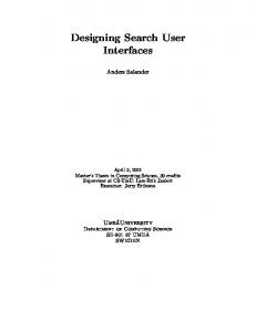
To test the conformity of the implementation with respect to the specification, we define a mapping establishing a correspondence between instance variables and operations of different levels of abstraction. Such mapping is illustrated in the test situation presented in fig. 4 (arrows labelled R and T).
Implementation
CS1: TBLogin.text = "user" TBPassword.text="" BOk.enabled=false
CF: TBPassword.setText(“guest”)
CS2: TBLogin.text="user" TBPassword.text="guest" BOk.enabled=true
R R
T SS2:
Specification
SS1: Login.text="user" Password.text="" Ok.enabled=false
SF: Password.setText(“guest”)
SS2A: Login.text="user" Password.text="guest" Ok.enabled=true
Fig. 4. A conformity test situation.
Assume that we are in a state (CS1 / SS1) where the login is already filled in, and the user fills in a password. At the implementation level, the method TBPassword.setText is called, taking as argument the string filled in by the user, the TextChanged event is raised and handled by the OnTBTextChanged method, which in turn updates the BOK.enabled property to true. We can perform a comparison-based test (test of kind A) or a contract-based test (test of kind B). Test A: Test I: The invariant is verified on state SS1: Ok.Enabled = Login.getText()"" and Password.getText()""
Tests II and V: Not applicable because operation setText in class MyTextBox has neither pre-condition nor outputs (messages sent to the user). Test VII: States SS2A and SS2 are identical. Test B: Tests I and II: As above. Test IV: Post-condition is verified: Text="guest" and container.Ok.getEnabled() = (container.Login.getText()"" and container.Password.getText()"")
Test VI: Invariant is verified on state SS2: Ok.Enabled = Login.getText()"" and Password.getText()""
6 Conclusions and Future Work The proposed architecture promotes the integration of formal methods in user interface development process. Activities like requirement specification of business logic and user interface, validation, design and verification are supported. This architecture links the often independently treated specification by formal methods and implementation levels. This integration is obtained through the user interface layout module that transmits user actions to the specification and implementation levels. Two maps (state variables and operations) that relate the specification with the implementation levels allow this communication. In this way, the objective of early validation of requirements with the client and running automatic conformity tests is attained while the connection makes it possible to have the product partially implemented during the demonstration or tests. A description of the automatic conformity tests was presented in the form of a state transition model. To illustrate the concept, a conformity test over the case of login/password dialog was presented. The dialog specification was made using VDM++ and the correspondent implementation was developed in C# code. In our future work we will: - Study the refinement process between the user interface specification and the implementation; - Study the possibility of automatic generation of the user interface style and layout and connection to the user interface logic specification; - Construct run-time support to automatic test of conformity. - Expand the approach to more complex patterns of user interfaces. - Analyze the possibility to propose enhancements to the VDM++ language in the context of user interfaces.
References 1. A. Puerta, The MECANO Project: Comprehensive and Integrated Support for ModelBased Interface Development, CADUI'96, J. Vanderdonckt (eds), 1996, pp. 19-36. 2. Bernhard K. Aichernig, Automated black-box testing with abstract VDM oracles. In John Fitzgerald and Peter Gorm Larsen, editors, Workshop Materials: VDM in Practice!, Part of the FM'99 World Congress on Formal Methods, Toulouse, pages 57–66, September 1999. 3. Carroll Morgan, Programming from Specification, Prentice Hall, 2nd ed., October 1998. 4. Daniel F. Gieskens and James D. Foley, Controlling User Interface Objects Through Preand Post-conditions, GVU Technical Report Number GIT-GVU-91-09, June 1991. 5. David Duke and Michael Harrison, Towards a theory of Interactors, Human Computer Interaction Group, Department of Computer Science, University of York, February, 1993.
6. Egbert Schlungbaum and Thomas Elwert, Automatic User Interface Generation from Declarative Models. CADUI'96, J. Vanderdonckt (ed.), 1996, pp. 3-18. 7. François Bodart, Anne-Marie Hennebert, Jean-Marie Leheureux, Isabelle Provot, Benoît Sacré, Jean Vanderdonckt, Towards a Systematic Building of Software Architecture: the TRIDENT Methodological Guide, DSVIS'95, Palanque & Bastide (eds), 5-7 June 1995, pp. 262-278. 8. Frank Lonczewski, The FUSE-System: an Integrated User Interface Design Environment, CADUI'96, J. Vanderdonckt (eds), 1996, pp. 37-56. 9. Ian MacColl and David Carrington, User Interface Correctness, Human Computer Interaction – Spring 1997 – 3.3. 10. John Fitzgerald and Peter Gorm Larsen, Modelling Systems Practical Tools and Techniques in Software Development, Cambridge University Press, 1998. 11. Liskov, B. H. and J. Wing. Behavioural subtyping using invariants and constraints. Technical Report CMU CS-99-156, School of Computer Science, Carnegie Mellon University, July 1999. 12. Morten Borup Harning, An Approach to Strctured Display Design - Coping with Conceptual Compexity, 2nd InternationalWorkshop on Computer-Aided Design of User Interfaces CADUI'96 (Namur, 5-7 June 1996), J. Vanderdonckt (Ed.), Presses Universitaires de Namur, Namur, 1996, pp. 121-138. 13. Philippe Palanque and R. Bastide, A Formalism for Reliable User Interfaces, Workshop Software Engineering/Human Computer Interaction associated with the IEEE/ICSE 16 conference, Sorento, Italy 16-22 May 1994. 14. S. Alagar and K. Periyasamy, Specification of Software Systems, Springer, 1998. 15. Sharon Flynn, Expression Refinement Explained, Information Technology Centre, National University of Ireland, Galway, 1999. 16. Thomas P. Browne, David Dávila, Spencer Rugaber, Kurt Stirewalt, Using Declarative Descriptions to Model User Interfaces with MASTERMIND, In F. Paterno and P. Palanque, editors, Formal Methods in Human Computer Interaction. Springer-Verlag, 1997. 17. Wing, J. M. Formal methods. In John J. Marciniak, editor, Encyclopedia of Software Engineering, pages 504-517. John Wiley & Sons, 1994. 18. http://www.ifad.dk/ifad.htm [conferred at 9/Oct/2002]. 19. http://beethoven.site.uottawa.ca/ELG7186W2000/cn00ch4B.ps
Appendix: Interactor specification library in VDM++ class EventHandler operations public handleEvent(e: Event) == is subclass responsibility; end EventHandler class Event instance variables private handlers : seq of EventHandler := []; operations public registerHandler(h : EventHandler) == handlers := handlers ^ [h] ext wr handlers post handlers = handlers~ ^ [h]; public raiseEvent() == executeHandlers(handlers); private executeHandlers(s: seq of EventHandler) == if s [] then let [h] ^ t = s in
(h.handleEvent(self); executeHandlers(t)); end Event class Control instance variables protected enabled: bool := true; protected visible: bool := true; protected text: seq of char := ""; public EnabledChanged: Event := new Event(); public TextChanged: Event := new Event(); public VisibleChanged: Event := new Event(); public Click: Event := new Event(); operations public getText() res: seq of char == return text ext rd text post res = text; public setText(t: seq of char) == if t text then (text := t; OnTextChanged()) ext wr text post text = t; protected OnTextChanged() == TextChanged.raiseEvent(); -- omitted similar member functions to handle visible -- and enabled properties public OnClick() == Click.raiseEvent() pre enabled and visible; end Control class Button is subclass of Control end Button class TextBox is subclass of Control end TextBox class Form is subclass of Control end Form class Message instance variables public static history : seq of seq of char := []; operations public static send(msg: seq of char) == history := history ^ [msg] ext wr history post history = history~ ^ [msg]; public static getHistory() res : seq of seq of char == return history ext rd history post res = history; end Message