mentation of interfaces (for example, bus interfaces and device drivers) a ... This
thesis presents one approach to hardware/software interface synthesis that ...
Specification, Synthesis and Validation of Hardware/Software Interfaces
Mattias O’Nils
Stockholm 1999
Electronic system Design, Department of Electronics Electrum 229, Isafjordsgatan 22-26 S-164 40 Kista, Sweden
Submitted to the School of Electrical Engineering, Royal Institute of technology, in partial fulfillment of the requirements for the degree of Technical Doctor.
Abstract Design based on intellectual property (IP) is emerging to close the gap between steadily increasing capacity, in terms of transistors on integrated devices, and design productivity, in terms of the number of transistors designed in a given period. However, the integration of several IP blocks into a single system on one chip makes the specification and implementation of interfaces (for example, bus interfaces and device drivers) a dominant design problem for embedded systems. There is therefore a need for effective ways of modelling, refining, and implementing communication within embedded systems. This thesis presents one approach to hardware/software interface synthesis that ranges from the specification to the implementation and validation of hardware/software interface protocols. The information required for hardware/software interface synthesis is separated into three parts: the protocol specification, information related to the operating system, and information related to the processor. From these inputs a synthesis tool generates (a) device driver functions, (b) a combination of device driver functions and a DMA controller, or (c) simulation models, depending on what the designer decides. The clean separation of information facilitates (1) efficient design space exploration with combinations of different processors, operating systems and protocols, and (2) efficient maintenance of a large number of different versions and variants of hardware/software interfaces. The three-phase validation approach is based on standard simulation methods and facilitates simulation of the interfaces at several steps during development. We keep all the simulation models consistent with both the specification and the implementation by generating the models using the same technique that is used for synthesis. Validation in several phases is justified (1) by the faster simulation of early phases (up to four times faster than late phases), and (2) by allowing both hardware designers and software developers to work in their familiar tool environments as long as possible. Protocols are specified as a grammar, which is fully independent of architecture and implementation. After the initial selection of implementation alternatives, the methods presented are fully automated. Using real-life examples we demonstrate the effectiveness of the simulation models and show that the quality of the generated code is close to handwritten quality in terms of performance, area and code size.
Acknowledgements I would like to begin by expressing my gratitude to Professor Hannu Tenhunen for accepting me as a PhD student at the Electronic System Design Laboratory. I would also like to send huge thanks to Dr Axel Jantsch for agreeing to be my supervisor and for his little jokes, which helped me overcome the setbacks caused by rejected papers and other obstacles. In my opinion Axel’s supervision has been a textbook example of how a supervisor should work. I am very grateful to Professor Ahmed A. Jerraya for agreeing to be the opponent of this thesis. I would also like to thank the people at the ESD Lab at the Royal Institute of Technology, especially Henrik Olson for making my stays in Kista more fun, and Johnny Öberg for his help during this work, together with the people at ITE, Mid Sweden University, for being good colleagues, specially Hans-Erik Nilsson and Bengt Oelmann for all the useful and fun discussions. Thanks also to Miguel Berg and the system administrators in both Stockholm and Sundsvall for helping me with computer problem and, of course, a big thank you to my golfing partners Claes Lindkvist, Stefan Pettersson and Per-Erik Näsholm, who together with the floorball team Sundsvall Academics helped take my mind off work. Ingalill Arnfridsson, you’re a well of patience and smiles. Thanks for all the help with arranging my travels and other boring administrative stuff during my time as a PhD student. I would like to thank the following for their financial support: Mid Sweden University, the Swedish National Board for Industrial and Technical Development – NUTEK, and the Swedish Foundation for Strategic Research – SSF. Lastly I would like to take the opportunity to thank my loving girlfriend Susanne for all her support and love. Without you, life would be so boring. Sundsvall, May 1999 Mattias O’Nils
Contents Abstract
i
Acknowledgements Contents
1
vii
List of Figures
xi
List of Papers
xiii
Introduction
Specification..............................................................................................7 Design .......................................................................................................9 Validation ................................................................................................10
History of codesign research ..................................................................... 10 2.2.1 2.2.2
2.3
Vulcan .....................................................................................................11 COSYMA................................................................................................12
Advanced research..................................................................................... 13 2.3.1 2.3.2 2.3.3 2.3.4 2.3.5 2.3.6 2.3.7 2.3.8
COSMOS ................................................................................................13 Polis.........................................................................................................14 CoWare....................................................................................................15 Chinook ...................................................................................................15 SpecSyn...................................................................................................16 Tosca .......................................................................................................16 Miscellaneous approaches.......................................................................17 Summary .................................................................................................18
HW/SW interface design 3.1 3.2 3.3
21
Definition................................................................................................... 21 Motivation ................................................................................................. 23 HW/SW Interface synthesis ...................................................................... 24 3.3.1 3.3.2
3.4 3.5
5
Design challenges........................................................................................ 7 2.1.1 2.1.2 2.1.3
2.2
1
Thesis outline .............................................................................................. 3
Embedded systems 2.1
3
v
Abbreviations and Acronyms
1.1
2
iii
Device driver synthesis ...........................................................................25 Bus interfaces synthesis ..........................................................................27
Validation................................................................................................... 27 ComSyn ..................................................................................................... 30 3.5.3
Objective .................................................................................................30
vi
Contents 3.5.4 3.5.5 3.5.6
4
Summary of papers 4.1
4.2
Paper 6, HLDVT 1998 ............................................................................ 39 Paper 7, IPSDP 1998............................................................................... 41
Author’s contributions ...............................................................................41
Thesis summary 5.1 5.2
43
Conclusions................................................................................................43 Future work................................................................................................44 5.2.1 5.2.2 5.2.3
6
Paper 3, DATE 1999 ............................................................................... 38 Paper 4, VLSI Design 1999 .................................................................... 39 Paper 5, Kluwer DAES Submitted 1999................................................. 39
Protocol validation.....................................................................................39 4.4.7 4.4.8
4.5
Paper 2, Euromicro 1998 ........................................................................ 38
Protocol synthesis ......................................................................................38 4.3.4 4.3.5 4.3.6
4.4
Paper 1, Norchip 1997 ............................................................................ 37 Paper 8, Norchip 1998 ............................................................................ 38
Protocol description ...................................................................................38 4.2.3
4.3
37
Analysis and problem formulation ............................................................37 4.1.1 4.1.2
5
Design flow ............................................................................................. 32 Target architecture................................................................................... 33 Protocol modelling in ProGram .............................................................. 34
Specification............................................................................................ 44 Synthesis ................................................................................................. 44 Target architecture................................................................................... 45
References
47
Paper 1
57
Paper 2
67
Paper 3
73
Paper 4
81
Paper 5
91
Paper 6
123
Paper 7
133
Paper 8
141
Abbreviations and Acronyms General ADC. . . . . . . . . . . . . . Analog to Digital Converter AMPS . . . . . . . . . . . . Advanced Mobile Phone System API. . . . . . . . . . . . . . . Application Program Interface ARM . . . . . . . . . . . . . Advanced RISC Machines ASIC . . . . . . . . . . . . . Application Specific Integrated Circuit ATM. . . . . . . . . . . . . . Asynchronous Transfer Mode CAD. . . . . . . . . . . . . . Computer Aided Design CAN. . . . . . . . . . . . . . Controller Area Network CISC . . . . . . . . . . . . . Complex Instruction Set Computer CMOS . . . . . . . . . . . . Complementary MOS CORBA . . . . . . . . . . . Common Object Request Broker Architecture CSP . . . . . . . . . . . . . . Communicating Sequential Processes D-AMPS . . . . . . . . . . Digital AMPS DAC . . . . . . . . . . . . . . Digital to Analog Converter DMA . . . . . . . . . . . . . Direct Memory Access DMAC . . . . . . . . . . . . DMA Controller DRAM . . . . . . . . . . . . Dynamic RAM DSP . . . . . . . . . . . . . . Digital Signal Processing EDA . . . . . . . . . . . . . . Electronic Design Automation FIFO . . . . . . . . . . . . . First In First Out FSM . . . . . . . . . . . . . . Finite State Machine GSM . . . . . . . . . . . . . Global System for Mobile Communications HCCS. . . . . . . . . . . . . Host Code Cosimulation HDL. . . . . . . . . . . . . . Hardware Description Language HLS . . . . . . . . . . . . . . High Level Synthesis HW . . . . . . . . . . . . . . Hardware I/O . . . . . . . . . . . . . . . Input/Output
viii
Abbreviations and Acronyms
I2C . . . . . . . . . . . . . . .Inter Integrated Circuit bus IEE . . . . . . . . . . . . . . .Institution of Electric Engineers IEEE . . . . . . . . . . . . . .Institute of Electrical and Electronic Engineers IP . . . . . . . . . . . . . . . .Intellectual Property ISR . . . . . . . . . . . . . . .Interrupt Service Routine ISS . . . . . . . . . . . . . . .Instruction Set Simulator LoC. . . . . . . . . . . . . . .Lines of Code MOS . . . . . . . . . . . . . .Metal-Oxide-Silicon NUTEK . . . . . . . . . . .Swedish National Board for Industrial and Technical Development OAM. . . . . . . . . . . . . .Operation and Maintenance OS. . . . . . . . . . . . . . . .Operating System ProGram . . . . . . . . . . .Protocol Grammar RAM. . . . . . . . . . . . . .Random Access Memory RISC . . . . . . . . . . . . . .Reduced Instruction Set Computer ROM. . . . . . . . . . . . . .Read Only Memory RPC . . . . . . . . . . . . . .Remote Procedure Call RTL. . . . . . . . . . . . . . .Register Transfer Level RTOS . . . . . . . . . . . . .Real-Time Operating System PC . . . . . . . . . . . . . . . .Personal Computer PDA . . . . . . . . . . . . . .Personal Digital Assistant SDL . . . . . . . . . . . . . .Specification and Description Language SSF . . . . . . . . . . . . . . .Swedish Foundation for Strategic Research SW . . . . . . . . . . . . . . .Software TCCS . . . . . . . . . . . . .Target Code Cosimulation TDMA . . . . . . . . . . . .Time Division Multiple Access UART . . . . . . . . . . . . .Universal Asynchronous Receiver Transmitter USART . . . . . . . . . . . .Universal Synchronous/Asynchronous Receiver Transmitter VHDL. . . . . . . . . . . . .VHSIC Hardware Description Language VHSIC . . . . . . . . . . . .Very High Speed Integrated Circuit VLSI . . . . . . . . . . . . . .Very Large Scale Integration VSI . . . . . . . . . . . . . . .Virtual Socket Initiative YACC . . . . . . . . . . . . .Yet Another Compiler Compiler
ix
Research groups and approaches AKKA . . . . . . . . . . . . Royal Institute of Technology’s early codesign approach CASTLE . . . . . . . . . . Codesign and Architecture driven Synthesis TooL Environment CCG. . . . . . . . . . . . . . Communication Classification Graph, defined in [89] CFSM . . . . . . . . . . . . Codesign FSM, defined in [28] Chinook . . . . . . . . . . . University of Washington’s codesign approach CodeSign . . . . . . . . . . Object oriented codesign approach, ETH, Zurich, Swiss ComSyn . . . . . . . . . . . Royal Inst. of Techonlogy’s HW/SW interface synthesis tool COSMOS. . . . . . . . . . An SDL-based Codesign Tool, TIMA, Grenoble, France COSYMA . . . . . . . . . COSYnthesis for eMbedded Architectures Cx . . . . . . . . . . . . . . . . Super set of C, defined in [50] ESG . . . . . . . . . . . . . . Extended Syntax Graph, defined in [19] FGM . . . . . . . . . . . . . Flow Graph Model, defined in [83] HardwareC. . . . . . . . . Modified C dialect for hardware synthesis LYCOS . . . . . . . . . . . LYngby COSynthesis system Polis . . . . . . . . . . . . . . A codesign system for control application, Berkley, USA PSM . . . . . . . . . . . . . . Program State Machine, defined in [55] RTC . . . . . . . . . . . . . . Register Transfer C, defined in[21] SOLAR . . . . . . . . . . . FSM based design representation, used in COSMOS SpecSyn . . . . . . . . . . . University of California - Irvine’s codesign approach STG . . . . . . . . . . . . . . Signal Transition Graph, defined in [80] Tosca . . . . . . . . . . . . . Politecnico di Milano’s codesign approach Vulcan . . . . . . . . . . . . Early codesign approach presented in [58]
x
Abbreviations and Acronyms
List of Figures Figure 1.1:
The growing gap between what engineering teams can design and what fabrication lines can economically produce [53]. ...............2 Figure 1.2: Organization of the thesis. ..................................................................4 Figure 2.1: Products that include embedded systems. ..........................................5 Figure 2.2: Typical embedded system...................................................................7 Figure 2.3: System synthesis design flow..............................................................8 Figure 2.4: Vulcan design flow............................................................................11 Figure 2.5: COSYMA design flow. .....................................................................13 Figure 3.1: Communication routes in a heterogeneous embedded system. ........21 Figure 3.2: Break down of the HW/SW communication into different parts. ....22 Figure 3.3: Simplified schematic of the pay phone controller system. ...............23 Figure 3.4: Mapping of hardware/software communication protocols onto selected architecture. ........................................................................24 Figure 3.5: HW/SW interface design flows. (a) Without HW/SW interface synthesis tool and (b) with a HW/SW interface synthesis tool. ...................................................................................25 Figure 3.6: Device driver protocol mapped onto an architecture........................30 Figure 3.7: Providing device driver implementation for two device driver protocols mapped onto two RT-kernels and two processors, using two different APIs, with and without DMA. (a) describes the generation of implementation with the ComSyn approach, and (b) with a handwritten library. ...................................................32 Figure 3.8: Overview of the ComSyn synthesis system......................................33 Figure 3.9: Simulation levels in embedded hardware/software systems development: (a) system description simulation, (b) HW/SW stub simulation, (c) HW/SW host code cosimulation, and (d) target code cosimulation. ............................................................34 Figure 3.10: Grammar rule with actions. ..............................................................35 Figure 4.1: Identification of paper contents in the ComSyn design flow. ...........37
xii
List of Figures
List of Papers Papers included in this thesis: 1. Mattias O’Nils, Axel Jantsch, “Communication in Hardware/Software Embedded Sys-
tems - A Taxonomy and Problem Formulation”, Proceedings of the 15th IEEE Norchip Conference, pp. 67-74, 1997. 2. Mattias O’Nils, Johnny Öberg, Axel Jantsch, “Grammar Based Modelling and Synthe-
sis of Device Drivers and Bus Interfaces”, Proceedings of EUROMICRO Conference, pp. 55-58, 1998. 3. Mattias O’Nils, Axel Jantsch, “Operating System Sensitive Device Driver Synthesis
from Implementation Independent Protocol Specification”, Proceedings of Design, Automation and Test in Europe (DATE), pp. 562-567, 1999. 4. Mattias O’Nils, Axel Jantsch, “Generation of DMA Controllers from Device Driver
Descriptions”, Proceedings of IEEE VLSI Design Conference, pp. 138-145, 1999. 5. Mattias O’Nils, Axel Jantsch, “Device Driver and DMA Controller Synthesis from
HW/SW Communication Protocol Specifications”, submitted to Design Automation for Embedded Systems, Kluwer Academics Publisher, 1999. 6. Mattias O’Nils and Axel Jantsch, “Multi-phase Validation of Hardware/Software Inter-
faces based on Generated Simulation Models”, Proceedings of the IEEE International High Level Design Validation and Test Workshop, pp. 40-46, 1998. 7. Mattias O’Nils, Axel Jantsch, “HW/SW Interface Validation in IP based System
Design”, Proceedings of International. Workshop on IP based Synthesis and System Design, pp. 79-84, 1998. 8. Mattias O’Nils, Axel Jantsch, “Refinement of HW/SW Communication Channels:
Case Study and Comparison”, Proceedings of the 16th IEEE Norchip Conference, pp. 230-237, 1998.
xiv
List of Papers
Other papers: 1. Mattias O'Nils, Kalle Tammemäe, Axel Jantsch, Ahmed Hemani, Hannu Tenhunen,
“Experiences using Akka: A Hardware-Software Codesign Tool Kit in design of Telecommunication systems”, Poster session of CAVE'95 Workshop, 1995. 2. Kalle Tammemäe, Mattias O'Nils, Axel Jantsch, Ahmed Hemani, “AKKA: A Codesign
Environment”, Proceedings of 13th Norchip Conference, pp. 249, 1995. 3. Mattias O'Nils, Axel Jantsch, Ahmed Hemani, Hannu Tenhunen, “Interactive Hard-
ware-Software Partitioning and Memory Allocation Based on Data Transfer Profiling”, Proceeding of International Conference on Recent Advances in Mechatronics, pp. 447452, 1995. 4. Kalle Tammemäe, Mattias O'Nils, Anders Tornemo, Hannu Tenhunen, “VLSI System
Level Codesign Toolkit AKKA”, Proceedings of the 14th IEEE Norchip Conference, pp. 196-202, 1996. 5. Mattias O'Nils, Kalle Tammemäe, Axel Jantsch, Ahmed Hemani, “Design of D-AMPS
Channel Decoder with Codesign Methodologies”, Proceedings of Baltic Electronic Conference, pp.397-400, 1996. 6. Kalle Tammemäe, Mattias O'Nils, Ahmed Hemani, “Flexible Codesign Target Archi-
tecture for Early Prototyping of CMIST Systems”, Field-Programmable Logic Smart Application, New Paradigms and Compilers, Springer-Verlag, ISBN 3-540-61730- 2, pp.193-199, 1996. 7. Kalle Tammemäe, Mattias O'Nils, Axel Jantsch and Ahmed Hemani, “AKKA: A Tool-
kit for Cosynthesis and Prototyping”, IEE Digest no:96/036 of Colloquim on Hardware-Software Cosynthesis for Reconfigurable Systems, pp.8/1-8/8, 1996. 8. Bengt Oelmann, Mattias O’Nils, “Asynchronous Control of Low-Power Gated-Clock
Finite-State Machines”, Proceedings of IEEE International Conference on Electronics, Circuits and Systems, 1999. 9. Bengt Oelmann, Mattias O'Nils, “A Low Power Hand-Over Mechanism for Gated-
Clock FSMs”, Proceedings of the European Conference on Circuit Theory and Design, 1999.
1 Introduction Many types of electronic systems exist and they can be found almost everywhere, for example, cellular telephones, toys, cars, and so on. Looking at the evolution of electronic products one can identify several characteristics that are becoming more important, and will therefore also influence the design process. The characteristics are increased system functionality, more-portable systems (that is, battery operated), and shorter product lifetime. Table 1.1 outlines how the different characteristics will influence the design process. The first and second columns indicate the product trend. Columns 3 and 4 show how each trend affects the design and the design process. Table 1.1: Electronic product trends and their effects on product design.
Product trend Increasing complexity
∆
This leads to
∆
Increasing design time Increasing power
Decreasing power
Increasing design time
Decreasing product lifetime
Decreasing design time
Both the increase in system complexity and the requirements for low-power operation lead to increased design time. Increased complexity can also lead to increased power consumption. Design time will therefore increase because the designer needs to put more effort into low-power design. At the same time, the decreased product lifetime requires a reduction in design time. The design task will thus become more complex and the design time for these systems will need to be reduced. In short, the electronic systems design process has to be made more efficient by using better design methods. In the past the driving force behind increased electronic system complexity has been the advances in silicon technology. Figure 1.1 shows that the gap is increasing between silicon capacity, in terms of the number of gates on a chip, and the size of designs. Thus the limitations are moving towards design productivity rather then technology capacity. This is becoming a problem for silicon vendors because their production capacity is not fully used, leading them to take more interest in design issues in recent years [6,15].
2
Log scale [Gates/cm2]
Introduction
3,830k
Moore’s Law
2,410k
1,520k
Widening Gap
957k 603k 380k
100k
1994 0.6µ
125k
1995 0.5µ
156k
1996 0.35µ
195k
1997 0.25µ
244k
305k
Average Cell-based Design Start 1998 0.2µ
1999 0.15µ
Figure 1.1: The growing gap between what engineering teams can design and what fabrication lines can economically produce [53].
In conclusion we see that there is a demand for more-efficient design methods from both consumers and producers of electronic systems. This demand also includes efficient design methods for low power. There are several ways of increasing electronic design productivity. This thesis concentrates on the system design of the digital parts of embedded systems. However, there exist several unsolved problems in other areas such as analog design [78], electronic system packaging [9] and the integration/testing of electronic systems [3,68]. There are two major ways of achieving increased design productivity: (1) using computer aided design (CAD) tools, and (2) using design based on intellectual property (IP) components. There are several techniques to achieve low-power operation for a system. This is also reflected in several research approaches for low-power implementations, for example: asynchronous logic [96], highly parallel low-speed structures [22,26], isosynchronous techniques [5,61] or power management techniques [17]. The predominant computer aid for hardware design is still schematic capture and logic synthesis [39]. Design tools for higher levels of abstractions are becoming more mature and have resulted in tools for graphical design [103] and tools for high-level synthesis (HLS) [24,54]. The reuse of hardware IP components is starting to gain recognition in the designer community. The VSI Alliance [117] for the documentation and exchange of hardware IP com-
1.1 Thesis outline
3
ponents is a good start, but there are still many issues that have to be solved to enable the complete success of IP-based hardware design, for example, copyright protection [27], the validation of IP components [38,93] and CAD tools for IP-based design (communication synthesis) [100,115,124]. Tools accepted and widely used by the software-designer community are C cross compilers and debuggers for particular microprocessors. These tools are usually not portable, that is, a software development system will only support one processor family (processor architecture). Only a few software CAD tools support different optimization strategies and analysis methods for size/performance/power constraints. Tools exists for higher levels of abstractions for software synthesis, that is, case tools [34,42]. These tools enable designers to work on a higher level of abstraction while the tools themselves handle the low-level implementation details. These tools have not yet gained widespread recognition. The reuse of software IP components (code) has been proposed and debated for a long time in the software community. It is only recently, with approaches like Corba [35] and JavaBeans [73], that IP-based software design has gained acceptance among designers. Hardware/software codesign1 is the next evolutionary step for embedded systems CAD tools. Hardware/software codesign research has been going on for about 10 years [46,55,82,118]. Although the joint design of hardware and software is much older than this, the concept of hardware/software codesign is to merge the design flows for hardware and software into one hardware/software design flow. In recent years codesign research has resulted in a few commercial design tools like Coware [21], Arexsys [105] and Felix [104]. Most approaches to hardware/software codesign focus on top-down design, that is, starting from a high-level specification that is then refined into an implementation. Only a few research groups focus on methods for IP-based design [47,92,122].
1.1 Thesis outline The next section goes through embedded systems, embedded systems’ design and the research in hardware/software codesign. Section 3 analyses the task of hardware/software interfacing and describes the related work in this area. It also describes the ComSyn system, that is, the hardware/software communication synthesis system presented in the appended papers. Section 4 summarizes the work covered by all papers included in this 1. “HW/SW codesign means meeting system-level objectives by exploiting the synergism of hardware and software through their concurrent design.” – Giovanni De Micheli, Stanford University.
4
Introduction
thesis. Section 5 summarizes and concludes the contributions of this thesis. It also indicates unresolved problems in communication synthesis. The eight papers that present the original contribution are appended to the end of the thesis.
1 Introduction
2 Embedded systems 2.1 Design challenges
2.2 History of codesign research
2.3 Advanced research
3 HW/SW interface design 3.1 Definition
3.2 Motivation
3.3 HW/SW Interface synthesis
3.4 Validation
3.5 ComSyn
4 Summary of papers
5 Thesis summary
6 References
Papers included in thesis HW/SW Communication analysis
HW/SW Protocol Specification
HW/SW Protocol Implementation
HW/SW Protocol Verification
Paper 1 Paper 8
Paper 2
Paper 3 Paper 4 Paper 5
Paper 6 Paper 7
Figure 1.2: Organization of the thesis.
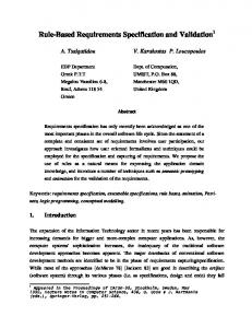
2 Embedded systems Today embedded computer systems have become everyday gadgets for most people, who use them even without even knowing it. Figure 2.1 and the bulleted items below show some examples of things, taken from the author’s daily life, that contain one or more embedded computer systems. Each example includes a description of tasks that can be carried out by embedded systems. • microwave oven – providing the user interface and controlling the cooking of food. • audio equipment – providing the user interface and processing the audio data. • engine preheater – providing the user interface and controlling the power to the pre-
heater in accordance with the user’s wishes and the climatic conditions. • cars – today cars usually contain several embedded systems: anti-lock brake controller,
ignition control, air conditioning controller, etc. • cellular phone – providing the user interface, encoding data, speech compression, etc. • TV set-top box – controlling the on-screen user interface, image processing, etc. • Answering machine – compressing and storing speech data.
One reason why embedded computer systems are so popular is the combination of highperformance hardware with flexible software that has a short design time. The first embedded systems were banking and transaction systems running on mainframes and
Figure 2.1: Products that include embedded systems.
6
Embedded systems
arrays of disks. Since this sort of equipment was built from very expensive components, it was used for relatively few but important applications. When equipment was as expensive as the early mainframes were, it was easy to motivate high costs for the design and maintenance of systems. What is an embedded system? There are probably as many definitions of what an embedded system is as there are designers. The word embedded implies that the system will not change after it has been designed, and that it has a specific task. This makes sense for the examples above, but there is actually no generally accepted definition of what an embedded system is. For example, is a PC that only runs a phone book application an embedded system? Or is a PDA that uses the same processor running the same phone book application an embedded system? All embedded systems mentioned in this thesis refer to hardware/software systems with one or more microprocessors, similar to the system shown in figure 2.2. An embedded system has several components (see figure 2.2), but the most important device, which has enabled the evolution of embedded systems, is the microprocessor [64]. The microprocessor has evolved from the simple 4004 [33] from Intel with only a few thousand transistors, to the microprocessors of today (1999) with 6.5 to 100 million transistors on a single chip, for example, the AlphaTM 21364 [13], the PowerPCTM 750 [102], the Pentium IITM[101]. The invention of the microprocessor enabled the use of embedded systems in low-cost consumer products like the ones listed above. The complexities of the processors mentioned above, together with memory devices containing up to 256 million devices on a single chip [1], have made it possible for chips to contain entire systems. This in turn enables system functionality well beyond traditional ASIC-based systems, for example, a whole GSM mobile phone can now be integrated on a single chip. The complexities of today’s systems mean that many problems will emerge during the design process, as mentioned in the introduction. First of all, the design of embedded systems embraces several design areas such as distributed system design for linking the system’s network of communicating microprocessors and real-time design to ensure that the embedded system operates within the time constraints set by the user. These constraints may be soft, as with a laser printer, where a delay in printing a page is not critical, or they may be hard, as with an autopilot, which must without fail respond in real time. Many embedded systems include at least a few hard real-time constraints. The designer’s job is to choose the engine that does the job most economically, but at the same time satisfy such constraints as physical size and power consumption. However, it is performance
7
2.1 Design challenges
Embedded System Processor Core(s)
RAM
ROM AD Converter DMA DA Converter I/O Interface(s)
Application Specific Logic
Figure 2.2: Typical embedded system.
constraints, particularly the hard real-time deadlines, that determine the basic requirements of a hardware engine.
2.1 Design challenges To refine an embedded system from idea to finished product, a designer has to perform a huge number of design and validation tasks. A great deal of effort is being put into developing a design tool that offers computer aided design support for the whole design process, but several design sub-problems have yet to be analysed and researched before a tool for system synthesis becomes reality. Figure 2.3 shows a design flow for the design of hardware/software embedded systems. The tasks within this design flow are identified below. The different design tasks are divided into three different classes: specification, design and validation. 2.1.1 Specification Many different aspects of a system have to be captured in a specification, that is, behaviour, architecture and requirements. Writing a specification is a very challenging task since the specification should be unambiguous, consistent and complete. Specifications have traditionally been captured, if at all, in natural language. The challenge for the future in the area of specification is to find formal methods of capturing the information needed to specify an embedded system.
8
Simulation Model checking Theorem proofing
Specification - Requirements - Behaviour - Architecture Executable spec. Spec. of control-flow
Spec. of data-flow
Partitioned spec. Design Task assignment Fix. arithmetic precision Estimation Scheduling of tasks HW/SW partitioning
Test Prototyping
Validation
Embedded systems
Communication synthesis Interface synthesis Code generation Generation of glue logic Integration Data-flow oriented
Control-flow oriented
Figure 2.3: System synthesis design flow.
• Behavioural specification. Captures the functional parts of a system, such as algo-
rithms and control flow. • Architectural specification. Describes the architectural parts of the system, that is,
describes all parts of the system that are reused (for example, processors and IP Components). • Requirements specification. Describes non-functional system requirements, for exam-
ple, throughput constraints, power consumption constraints and descriptions of external interfaces. • Executable specification. Captures the behaviour of the system in a format that can be
executed on a computer, thus enabling validation and elaboration of system properties.
2.1 Design challenges
9
• Specification partitioning. Partitions a specification into, for example, control- and
data-flow dominated parts, that is, individual specifications of parts of the system that need to be handled in different design flows. 2.1.2 Design To transform a specification into an implementation, a designer has to go through several refinement steps. The design task can be divided into four stages: (1) applying the specification to a specific implementation and estimating design properties, (2) assigning the specification to execution units and scheduling it, (3) synthesizing the interconnections, and (4) code generation and integration. • Task assignment. Break down the specification into a set of tasks that perform the sys-
tem functionality to enable concurrency and optimization. • Fix arithmetic precision. For fixed-point implementation, the arithmetic width has to
be defined and verified so that the implementation meets the initial specification. • Estimation. Estimate cost parameters for both hardware and software. Cost parameters
can be, for example, timing performance, gate count (HW), code size (SW), power, memory size, and statistics on execution frequency. Estimated values are used to aid designers/tools to make design decisions, thus decreasing the number of design iterations. • Allocation. Allocate a set of processors and execution units that will deliver enough
computation power to meet all cost, performance and other constraints. • Hardware/software partitioning. Partition a system into multiple processors and other
execution units. Partitioning decisions should consider timing, power and other cost constraints. • Scheduling. Find a system schedule and allocation, taking into consideration timing
constraints and the need to minimize system costs. • Communication synthesis. Define the communication protocol from the system specifi-
cation, select a suitable communication architecture that fulfils a set of communication constraints, and map the communication protocol onto the selected architecture. • Code generation. Generate code that is optimized for each specific execution unit. • Integration. Integrate hardware, software, memory, etc. into a complete system.
Most of the design tasks will affect each other’s results. For example, the allocation will affect the partitioning, scheduling and communication synthesis, but at the same time the communication synthesis can affect all the others. The quality of all design decisions depends on the quality of the estimation values.
10
Embedded systems
2.1.3 Validation System validation, which is carried out at the same time as the design and specification activities, includes verifying the specification, checking that models are consistent with each other and testing the final system. • Formal verification. Check models between abstraction levels and proof specifications. • Simulation. Generate accurate simulation models. Provide simulation models for
cosimulation, for example, hardware/software cosimulation and data-flow/control-flow cosimulation. • Prototyping. Rapidly develop an accurate implementation for evaluation, validation
and demonstration purposes. • Test. Verify that the final implementation of the system meets the initial system specifi-
cations.
2.2 History of codesign research As mentioned in the introduction, the research field of hardware/software codesign is about 10 years old. That is, the research for design methods where there is no bias towards a hardware or software implementation in the initial specification and the design processes for hardware and software have been merged. Initially almost every group that worked on hardware/software codesign developed their own hardware/software partitioning technique. There were approaches that attempted to speed up the initial software implementation by integrating computationally intensive parts into hardware [8,45,49,69,94]. Others attempted to partition a set of parallel processes into hardware and software [14,58,113]. Most of these approaches had evolved from high-level synthesis. As the research field has matured a wider range of research topics has been dealing with, for example, specification [15,71,122], architectural modelling [47,123], partitioning [48,63,66], scheduling [32,108,110], estimation [52,56,119], communication synthesis [36,97,115], validation [41,114], code generation [16,77,79] and prototyping [25,60,109]. The most mature topic is hardware/software cosimulation, which has earned a wide recognition in the designer community with tools like Seamless and the Eagle [41]. Another area that has resulted in a few start-up companies is communication synthesis, that is, CoWare [21], Arexsys [105] and Felix [104]. Even though these tools have more features, it is the cosimulation and communication synthesis techniques that are most important.
11
2.2 History of codesign research
HDL Specification
Compilation Graph Model Constraints analysis Partitioning
Program Graph
ASIC Graph Model
Interface
Code synthesis Interface gen. C Program
Structural synthesis
Compilation Assembly Program
ASIC Netlist
Simulation
Mixed System Implementation Figure 2.4: Vulcan design flow.
To illustrate the initial research efforts, the following two subsections present two different research projects. Each represents one class of approaches: COSYMA [49] (speed-up of software) and Vulcan [58] (evolved from HLS research). The remaining parts of the section describe the leading approaches in hardware/software codesign research. 2.2.1 Vulcan VULCAN takes a HardwareC specification [83] (hardware description language that is a subset of C with processes) as input. The description is compiled to a data flow graph model, FGM, that allows multiple threads. Starting with the whole system in hardware, functionality is successively moved to software. Global and local timing constraints can be expressed in the specification and a key feature of the partitioning is that it carefully analyses these timing constraints to meet them while minimizing design costs.
12
Embedded systems
Interprocess communication is modelled with send/receive primitives. The tool accepts blocking, non-blocking and buffered communication. All communication between processes is performed through static channels. The tool generates a buffered structure for synchronization and scheduling between processes. The first assumption made is that non-deterministic operations related to data-dependent loop operations define the beginning of program threads in software, while all other operations are implemented in hardware. If the initial assumption is feasible, iterative improvement is achieved by migrating deterministic operations between the partitions. Operations for migration are selected so that the move lowers the communication costs while maintaining satisfactory timing constraints. In addition, communication feasibility is checked by verifying the process communication for each thread and ensuring that processor and bus use constraints are satisfied [58]. The output from the system is C code for software and FGM for hardware (see the design flow in figure 2.4). 2.2.2 COSYMA The front-end language to the COSYMA system is a Cx (C extended with processes) description that is compiled into an internal graph-based representation, extended syntax graph (ESG) [19]. The graph is scheduled [18] into a single serialized process, and a system speed-up constraint is calculated to meet the timing constraints. The objective of the partitioner in this system is to move basic blocks from software to hardware until the system speed-up constraint is fulfilled [62]. The partitioning process is divided into two steps: firstly, an estimation-based partition that uses simulated annealing (inner loop) and, secondly, an evaluation of the partition feeds back the real values to the inner loop (outer loop). The simulated annealing in the inner loop starts with an all-software solution and extracts hardware iteratively until all timing constrains can be met. The objects extracted for hardware are basic blocks. To calculate the speed-up for each block the difference between the software execution time and the sum of the hardware execution time and the hardware/software communication time is measured. Software execution time is captured using execution profiling refined through static analysis. For the hardware execution time, each basic block is scheduled to a fixed data path. A hardware cost is generated from the schedule. The selected partition from the inner loop is evaluated in a cosimulation environment. If the constraints are still fulfilled the partition is accepted, otherwise the real values from synthesis are fed back to the inner loop. The output of the system is C code for software and an RTL VHDL for the hardware (see figure 2.5 for the design flow).
13
2.3 Advanced research
Inner partitioning loop Communication protocol
Cx system description Cx compiler
Simulator
Communication protocol
ES graph ES-graph -> C
partitioning
ES-graph -> CDFG
C-description
costestimation
CDFG description
C compiler (GNU) object code
Outer partitioning loop
high-level synthesis
run time analysis Figure 2.5: COSYMA design flow.
Communication in the Cx specification is modelled as logical static channels and bundles of channels. These logical channels can be mapped in the specification onto some predefined communication device/resource. The channel service functions are blocking and non-blocking send/receive, taken from a communication library [50].
2.3 Advanced research 2.3.1 COSMOS Jerraya et al. use SOLAR [74] as an intermediate language. It supports system level modelling and synthesis. SOLAR is based on a finite state model extended with concepts of hierarchy and parallelism and can be generated from C, VHDL and SDL. The design specification is partitioned by an interactive toolbox called Partif [67]. Partitioning starts with a set of hierarchical and communicating processes that are characterized by a cost
14
Embedded systems
function and performance. The partitioning tool allows the user to apply system level transformations to the design: move, merge, split, cut and map. These transformations are applied manually by the designer. The designer chooses which transformation should be applied based on information about interconnection, variable sharing, states, operators in the data path and local variables. The result from the partitioning tool is a set of design units connected by abstract channels. The communication semantics are based on the concept of rendezvous channel communication via send/receive operations. The types of protocols supported include blocking and non-blocking communication. A channel is implemented by allocating communication units from a library [36]. These library units are composed to fulfil a set of constraints put on the channel. The library consists of a set of communication services and protocols together with their implementations (a mixture of hardware and software). Interface synthesis techniques are used to permit communication between the processor and the chosen communication units. The research efforts in the COSMOS system have led to a commercial set of tools called Arexsys [105]. 2.3.2 Polis Polis [10] is focused on control-dominated applications with system architectures composed of a single processor surrounded by custom or library hardware. Polis uses Codesign Finite State Machines (CFSM) [28] as the internal representation for a system description, separating communication, behaviour and timing of the system. The CFSM is a finite state machine extended with a data path. The communication model is globally asynchronous, locally synchronous, with non-blocking finite buffers between CFSMs. So far, translation from Esterel [59] to CFSM has been reported. The description is manually partitioned with guidance of estimation values. C code and HDL code is generated from the CFSMs mapped to software and hardware respectively. Except for the I/O drivers and code generated from the CFSMs, the software code consists of a generated application-specific operating system for the selected processor. All communication within software or between software and hardware occurs through shared memory, I/O ports or memory-mapped I/O. The synthesized hardware includes the address decoders, multiplexers, latches and glue logic. Special-purpose hardware must follow a simple, data/strobe-based protocol to make it suitable for interfacing with other CFSMs. The Polis project has led to a commercial set of tools called Felix [104].
2.3 Advanced research
15
2.3.3 CoWare CoWare [21] is a design environment for heterogeneous hardware/software systems on a chip. CoWare’s main focus is system integration and the handling of communication in embedded systems. CoWare accepts heterogeneous communicating processes, which are specified in a super set of C. This description is then manually refined down to an RTL description in register transfer C (RTC) or in VHDL/DFL. The heterogeneous specification is mapped onto different processors (DSP, microcontroller or hardware). Software is generated with either an application-specific real-time kernel or generated by using software synthesis techniques [116]. Interprocess communication is done with point-to-point communication channels. The communication semantics are based on the concept of rendezvous channel communication via send/receive operations. Hardware/software communication channels are mapped onto a fixed architecture. This architecture is based on several library models. For software, the communication procedures are captured as parametrized C functions that are mapped onto a software model, that is, they adapt to processor-specific I/O handling, interrupt handling, etc. For hardware, a hardware interface cell is generated to connect via a handshake protocol to an I/O control unit [80,115]. This I/O control unit is a link between the processor and the handshake protocol. 2.3.4 Chinook The Chinook [30,31] approach extends the commonly used concept of device driver to include the bus interface as well. The driver/interface is described in a timing diagram description (SEQ), which captures both the behaviour and timing constraints for the interface. The description is synthesized into low-level software code that accesses the device via the ports of a microcontroller (for example, Intel 87C51 [2]) together with the required glue-logic. The synthesis procedure tries to find the cheapest implementation (smallest amount of hardware) regarding both timing and resource constraints. In their later work, Ortega et al. [29,97] expand the approach to communication synthesis for a distributed system. Input to the system is a behavioural description consisting of communicating processes. The processes communicate with each other via messages sent through ports connected by channels. All communication is of broadcast type, that is, one to many unidirectional. For each output port, the designer selects a high-level abstract protocol, that is, blocking or non-blocking, along with a deadline constraint. For each input port, the designer selects the appropriate queuing semantics. The designer also
16
Embedded systems
defines a system architecture that consists of heterogeneous processors connected by standard bus protocols (for example, CAN [121] and I2C [65]). Processes and communication channels are then mapped onto the selected architecture. The system then generates the communication interfaces. If there is no direct connection between two communicating processes, intermediate hop processes are automatically inserted to route a message from one bus to another bus. For each processor, a customized real-time operating system is generated that includes a real-time scheduler, a message routing process and device drivers. 2.3.5 SpecSyn SpecCharts [55] is used for capturing the system’s behaviour in SpecSyn. It is based on hierarchical program state machine (PSM). The PSM description allows VHDL code within the states. Communication in SpecCharts is modelled with shared variables. In later publications the group presents a specification language, SpecC [122], that has promising characteristics for IP-based design, that is, better support for interfacing of components, hierarchy and communication. So far, only specification methods using SpecC have been reported. In SpecSyn the SpecChart specification is compiled into an internal representation. Based on an estimation of cost and performance [56] several design refinement methods are applied to the system representation, that is, the allocation of processing elements and partitioning [113]. SpecSyn generates buses for communication between two processes using a technique called interface refinement. By analysing the size of the data communicated along with the rate of data generation, the bandwidth of the generated bus (number of wires and rate of transfer) is determined and the communication channels merged onto the bus. An abstract protocol is then directly implemented using additional control wires. Arbiters are synthesized to control access to the bus. The software send and receive subroutines are modified to use the synthesized bus. 2.3.6 Tosca Functionality in TOSCA [11] is captured in an OCCAM [75] description. OCCAM is built on communicating sequential processes (CSP). High-level languages like C (software) and VHDL (hardware) can be mapped/connected to the OCCAM description. Only processes that are written in OCCAM can be used in the exploration of the design space. Processes connected to the OCCAM description, for example, C, VHDL, are mapped to software and hardware respectively. The partitioning process starts with expanding the
2.3 Advanced research
17
description to parallel processes at the top level. Processes suitable for hardware or software are preallocated to the best implementation. The last step consists of pair-wise collapsing processes to new processes, considering user-defined closeness criteria. This is done until a user-specified cost constraint is fulfilled [12]. For software synthesis, a virtual machine code (VIS [7]) is generated from the OCCAM code. The implementation assembler code for the selected processor is then generated by translation from the virtual machine code. To verify and evaluate the design quality the TOSCA environment also provides a cosimulation facility, where the virtual machine code is executed in a VHDL model. The virtual processor accesses the system bus through a bus interface for the selected processor. The hardware/software interfaces are implemented with library functions on the software side and a fixed interface structure on the hardware side. 2.3.7 Miscellaneous approaches The seven approaches presented in detail in this section represent the most recognized and successful research groups. However, they still represent only a fraction of the work being done in hardware/software codesign. Some other research approaches are described in brief below. The author refers readers interested in hardware/software codesign to [46,55,82,118]. Lycos [81] is a system for speeding up C programs by implementing computationally intensive parts in hardware. The main application area has been image processing. Camposano et al. [23] present a similar approach called CASTLE. One system that has focused on data-flow-dominated systems is Cool [86]. Cool uses a subset of VHDL for specification. The main objective of Cool is heterogeneous implementation and its creators present several partitioning algorithms. Eles et al. [48] also present several different hardware/software partitioning algorithms. AKKA accepts system specification in C++ and partitions it into hardware and software components and synthesizes interfaces between them. The hardware component is coded in behavioural VHDL. Principal features of AKKA [72] are as follows: performance analysis, hardware/software partitioning [94] and cosimulation and coemulation environment [70,111]. The CodeSign [47] project presents an approach that starts with a heterogeneous specification. The tool supports several design refinements. The project also proposes methods
18
Embedded systems
for object-oriented modelling of the architectural parts. The architectural model is used during interface synthesis. Programming language Java is a hot topic in the information technology industry, which has led to several proposals for using Java for hardware/software codesign. Fleischmann et al. [51] use Java for specifying dynamically reconfigurable embedded systems. Young et al. [120] present a method for using JavaTime (extended Java) for specifications and their successive refinement. 2.3.8 Summary Even though a considerable amount of work has been done in the field of hardware/software codesign there are still several problems to be solved. One can observe that from the initial approaches, in which research was often aimed at automatically transforming a specification into an implementation, researchers now tend to focus on more specific problems. This is also the case in this thesis, which concentrates on the design of hardware/software interfaces or, more specifically, the specification, synthesis and design of the device-driver part of hardware/software interfaces. On studying the work done in the area of hardware/software with respect to interface design, one can observe that tools like CoWare [21], Polis [10] and Cool [86] are primarily designed for situations in which the whole design functionality is captured in its environment, with communication then being refined during system synthesis, that is, the device drivers are generated together with the custom hardware and an application-specific operating system. If designers use IP blocks and off-the-shelf real-time operating systems (RTOS), they are faced by the same problems that occur in manual design as described by Tuggle in [112]. COSYMA [49] and Lycos [81] use libraries for the hardware/software interfaces, which only moves the problems to the provider of the library. CodeSign [47] and MakeApp [57] are two tools that support the interfacing of IP components. CodeSign generates the interface code and an application-specific real-time kernel for the selected processor. It even supports some DMA access from data-flow specifications. MakeApp is a tool for generating device drivers for different devices and processors matching user-defined configurations. The work presented in this thesis, ComSyn, deals with hardware/software interface synthesis that ranges from the specification to the implementation and validation of hardware/software interface protocols. ComSyn takes an architecture- and implementationindependent description of the hardware/software interfaces as well as libraries capturing
2.3 Advanced research
19
the architecture. From these inputs a synthesis tool generates (a) device driver functions, (b) a combination of device driver functions and a DMA controller, or (c) simulation models, depending on what the designer decides. The clean separation of information facilitates (1) efficient design space exploration with combinations of different processors, operating systems and protocols, and (2) efficient maintenance of a large number of different versions and variants of hardware/software interfaces. This is not achieved by any of the other approaches. A careful examination of the problem and a review of the work done in hardware/software interfacing is presented in the next section, which also contains a thorough presentation of ComSyn, the tool for handling of hardware/software interface design developed by the author.
20
Embedded systems
3 HW/SW interface design In [89] we discussed the specification and implementation of communication in an embedded system. There we identified several different communication routes in a hardware/software embedded system, which includes both hardware and software library components (see figure 3.1). A communication specification can be mapped onto a large set of heterogeneous implementations (see table 3.1). If the specification can be mapped onto a distributed system the implementation set will be even larger and the communication synthesis task even more complicated. In [89] we also analysed the research dealing with communication in embedded systems. This analysis led us to focus on the hardware/software interfacing of IP components, since this was not well covered in the research work we found.
3.1 Definition A hardware/software interface can consist of up to four parts: (1) device driver functions, (2) direct memory access (DMA) controller, (3) bus interface, and (4) the register file and handshake behaviour of the device. A device driver is the wrapper for a hardware device
Hardware 7 H21
Software 11
Library modules 5
H11 6
Coprocessors
9
3
H12 8 Library component
Processors
P11 2 1
10 4 P21
Figure 3.1: Communication routes in a heterogeneous embedded system.
P22
22
HW/SW interface design Table 3.1: Communication routes in an embedded system.
#
Description
1. 2. 3. 4. 5. 6. 7. 8. 9. 10. 11.
SW process connected to another SW process on the same processor. SW process connected to another SW process on a different processor, with the same or a different operating system. SW process connected to an HW process (coprocessor). SW process connected to a peripheral, for example, off-the-shelf component, library module, etc. SW process connected to a library SW module. HW process connected to another HW process on the same chip (partition). HW process connected to another HW process on another chip (different partitions). HW process connected to a peripheral, for example, off-the-shelf component, library module, UART, etc. HW process connected to an SW process. Peripheral connected to an SW process. HW coprocessor connected to a library SW module.
accessed from software. The device driver’s behaviour is essentially that of a protocol defining how the device is accessed and synchronized with software. A device driver can perform all accesses to the device directly or it can use DMA to transfer data between two places in the address space. In the last case the device driver controls the DMA controller, which in turn accesses memory and other devices. Processor RTOS
b. I/O data to/from application program
initialize(...); open(...); read(..., data) {...} write(..., data); close(...); interrrupt_handler();
thread_5
thread_4
thread_3
thread_2
thread_1
Application program
Device drivers & Interrupt handlers dev_1
dev_2
dev_3
Bus interface Interface logic Device register register_1 register_2 register_3 Device register_4
DMA controller 00 01 02 03
a. Device driver entries c. Device driver behaviour
e. DMA controller behaviour f. DMA controller register file.
d. Device memory and registers
Figure 3.2: Break down of the HW/SW communication into different parts.
23
3.2 Motivation
Figure 3.2 illustrates the dependence of a device driver on various other parts, both hardware and software. We can observe that a device driver contains information on: (a) processor architecture and behaviour, (b) real-time kernel behaviour, (c) device architecture and behaviour, (d) access protocol of the device, (e) application programmer interface (API) rules, and (f) DMA controller architecture and behaviour. Device drivers thus accommodate a very high information density and are dependent on many parts that can appear in a large number of combinations. This fact is the reason for the low productivity of device driver modelling, which is four times lower than for ordinary software code [20].
3.2 Motivation
USART
USART
USART
Keyboard Display controller controller
Real-time clock
Counter array
Memory
USART
ARM7
Timers
I2C DMA interface controller
Figure 3.3: Simplified schematic of the pay phone controller system.
Días et al. [40] present a good example of design using IP components, in which more than 60% of the design consists of IP components. It illustrates how time-consuming the task of interfacing IP components can be, that is, design of the hardware/software communication parts of the system. Figure 3.3 shows a simplified schematic of the system, which is a pay phone controller. Consider the following design scenario: A system designer needs to evaluate the impact DMA controllers have on the system performance by comparing two alternative architectures of interfaces with the USARTs in figure 3.3: (1) no DMA controller, and (2) DMA controllers to interface the USARTs. The assessment is difficult because of the many dependencies, and a simple calculation is not accurate enough. This is supported by the observation that in many practical situations the traffic on the bus is identified as a performance bottleneck only after the system has been built. Ideally the two alternative architectures should be compared using simulation with all the interface details included in the simulation models. However, without tool support this is a formidable task because the designer must develop an entirely different interface code for each configuration and component. This is necessary because of the huge difference between implementing a hardware/software communication protocol in pure software and implementing it with a DMA controller. This task is so time-consuming that
24
HW/SW interface design
system designers typically consider a very limited number of design alternatives, and frequently only one. On the other hand a tool is perfectly capable of generating efficient models for this purpose from a high-level specification of the communication protocols, as this thesis shows. In addition to the evaluation of different architectures, there is the task of configuring a system for different product versions and product generations. For example, in a second version of the product it is decided to use a different processor and real-time kernel, but the functionality is the same. If the interface code was written with reuse in mind, that is, macros for real-time kernel functions and processor instructions are used in the code, most of the code can be reused. Only the APIs of the code have to be adapted to fit the new architecture. However, a new processor will require another DMA controller. The interface code dependent on the DMA controller therefore has to be redesigned. Now consider the evaluation and design architecture upgrade tasks using a tool for hardware/software communication. The designer maps a protocol description of the interfaces onto an architecture, that is, real-time kernel, processor and DMA controller (see figure 3.4). The communication synthesis procedure transforms the protocol descriptions into Processor HW/SW com. protocol
DMAC Real-time kernel Device driver
Figure 3.4: Mapping of hardware/software communication protocols onto selected architecture.
architecture-specific device driver code and application-specific DMA controllers. This enables IP providers to supply a wrapper for IP components. A designer that uses these IP components therefore only has to use the tool to generate the interface code for the specific architecture. Figure 3.5 illustrates the differences in design flow between manual and computer aided hardware/software interface design.
3.3 HW/SW Interface synthesis Many research groups have recently focused on the problem of communication synthesis for embedded real-time systems [98]. However, none of them has fully dealt with the problem described above. Tools like CoWare [21], Polis [10] and Cool [86] are primarily designed for cases in which the whole design functionality is captured within the tool’s
25
3.3 HW/SW Interface synthesis
b.
a.
DMA
kernel
processor device
API
device
protocol
kernel
DMA
protocol
processor
Library
Designer
API
Designer Device Driver
Bus Interface
HW/SW interface synthesis Device Driver
Bus Interface
Figure 3.5: HW/SW interface design flows. (a) Without HW/SW interface synthesis tool and (b) with a HW/SW interface synthesis tool.
environment and communication refined during system synthesis, that is, the device drivers are generated together with the custom hardware and the operating system. However, if users want to use IP blocks and off-the-shelf real-time operating systems (RTOS), they will face the same problems that occur in manual design [112]. As described above, a hardware/software interface consists of several parts that have to be generated during hardware/software interface synthesis. When generating hardware/software interfaces between software and hardware IP components, however, the interface synthesis task is reduced to the generation of device drivers (including DMA controllers) and bus interfaces. 3.3.1 Device driver synthesis Most codesign approaches support the generation of device drivers when a system description is synthesized down to an implementation. The interfacing of hardware library components is only supported in a few research projects [47,57,91]. Most approaches to hardware/software interface synthesis use a parametrized library for the device driver generation. This is the case for CoWare [21], where communication channels are mapped onto library procedures (device drivers). These device drivers are captured as parametrized C functions that are mapped onto a software model, that is, they adapt to processor-specific I/O handling and interrupt handling. A library component is therefore interfaced by writing parametrizable C functions. This is also the case for the Polis system [10].
26
HW/SW interface design
The Chinook [30,31] approach extends the commonly used concept of device driver to include the bus interface. The driver/interface is described in a timing diagram description (SEQ), which captures both the behaviour and timing constraints for the interface. The description is synthesized into low-level software code that accesses the device via the ports of a microcontroller (for example, Intel 87C51 [2]) together with the required gluelogic. The synthesis procedure tries to find the cheapest implementation (smallest amount of hardware) regarding both timing and resource constraints. In their more recent work, in which communication routes are synthesized onto a distributed architecture [97] with standard bus protocols, the device drivers are captured as library elements. In COSMOS [66] a communication channel is implemented by allocating communication units from a library [36]. These library units are composed to fulfil a set of constraints put on the channel. The library consists of a set of communication services and protocols together with their implementations (a mixture of hardware and software). MakeApp [57] is a tool for generating device drivers for different devices and processors matching user-defined configurations. MakeApp solves only part of the problems described in [112] since it does not support operating systems. This means that for example semaphores sometimes needs to be inserted when an operating system is used. Eisenring et al. [47] present a method for modelling the target architecture by means of object-oriented methods. The architectural model is used to generate hardware/software interfaces from data-flow descriptions. This is the only approach, besides ours, that handles the mapping of hardware/software communication onto DMA, but their approach is limited to a set of standard APIs and cannot handle more complex protocols, as in our approach [87,91]. The approach to device driver synthesis presented in this thesis is unique regarding the clean separation of behaviour and architecture [91,92], the efficient techniques for modelling, and the full support of direct memory access (DMA) [87,91]. The separation of behaviour and architecture enables the efficient reuse of the protocol descriptions since they can be mapped onto any combination of processors and real-time kernel. Protocols can also be mapped to an implementation using DMA. The information and size of the interface descriptions are much smaller than other modelling techniques [90,91,92,95].
27
3.4 Validation
3.3.2 Bus interfaces synthesis Bus-level protocols for components are usually described graphically by means of timing diagrams in a data sheet. For this reason [31] and [85] have developed specification languages based on timing diagrams. One problem with these approaches is that it is not possible to specify high-level behaviour. Lin et al. model the interface with an extended STG (signal transition graph) [80] based on Petrinets. They can use this modelling technique to model asynchronous events, and an extended-STG model to perform asynchronous synthesis. This approach enables the modelling of more complex behaviours. [44] and [55] use hardware description languages to model bus interfaces. Gajski et al. use a program state machine (PSM) to specify interfaces, but in all examples they use the HDL capability of the PSM to model interfaces. Öberg et al. present a communication protocol synthesis tool that specifies the design in a special-purpose language, ProGram [124], which is based on context-free grammar. The synthesizable subset is limited to a regular grammar with attributed conditions. Table 3.2 shows a comparison between some of the approaches described above and the extended version of ProGram presented in this thesis. The table shows that interfaces presented by other research groups are modelled more efficiently in ProGram. The example for SEQ in row 4 is an asynchronous circuit, which is the primary target for SEQ but not for ProGram. The ProGram model is still comparable with the SEQ model, however, and better suited to synchronous interfaces than SEQ. Table 3.2: Comparison of Lines of Code (LoC).
Reference model HDL (VHDL), list 1 in [44]
LoC
ProGram
Ratio
20
5
4.0
Extended TD, fig. 1 in [85]
16a
7
N.a.
PSM, fig. 8.10 in [55]
21 6 11
12 6 6
1.8 1.0 1.8
Timing diagram (SEQ), [32] Petrinets (E-STG), fig. 5 in [80] a. Number of conditions specified graphically.
3.4 Validation Validation is as important as design, since a design does not have any value until the designer knows that it fulfils the desired behaviour. In the traditional method of validating hardware and software in embedded system design, software is typically developed after a
28
HW/SW interface design
hardware design has begun to stabilize and prototypes are available for the integration of the hardware and software. This method provides limited visibility of both hardware and software operations. Software can also be prototyped in a host environment in which hardware/software communication is replaced by device drivers that emulate the hardware behaviour [84]. The problem with this approach lies in ensuring that the emulation models are consistent with the implementation. The alternative to the sequential validation of hardware/software communication is the emerging technology of hardware/software cosimulation [41]. Cosimulation means the simulation of a model of the hardware executing the software. This simultaneously provides both visibility and control of the hardware model while allowing software execution to be controlled and observed at all the levels of detail required to understand the behaviour of the system. Cosimulation leads to radical improvements in productivity because of the decreased effort required to model different levels of abstractions. This increased productivity comes at the cost of low simulation performance caused by the cost of the synchronization between the software and hardware simulation. Cosimulation can be performed at several different levels of abstraction and can be implemented in several different ways. Host code cosimulation: Host code cosimulation (HCCS) is when software is executed on the host workstation and the hardware/software communication is linked to a hardware simulator. HCCS can be performed with or without a bus interface. With a bus interface, a simulation device driver connects the software to the hardware simulator via the bus interface and addresses the device in the same way as it does in an implementation [107]. In cases where there is no bus interface, the hardware and software, for example, C and VHDL code, communicate with a handshake protocol [114]. RTL model of processor: The simplest method for hardware/software cosimulation is to develop an RTL model in HDL of the processor on which the target code is executed. This method can be improved by implementing an instruction set simulator connected to an HDL interface [4]. Cosimulation bridge tool: A bridge tool for cosimulation is a tool that connects two or more simulators, that is, it handles the synchronization and interaction between them. In the case of hardware/software cosimulation it is connecting an instruction set simulator (ISS) with an HDL simulator or a gate level simulator [43,107]. More general bridge tools also exist, such as Ptolomy [37], which can connect a large set of heterogeneous simulators. Valderrama et al. [114] present an approach in which they generate the simulation
29
3.4 Validation
models from an interface description. This approach is similar to ours [88,93], with the exception that we generate simulation models for commercial tools like Seamless [107] and support higher abstraction levels. Commercial hardware/software cosimulation tools like Seamless and the Eagle tools support selective focus as a mechanism to reduce simulation time. Simulation speed-up is achieved by filtering the data passed between the processor and the hardware. These filters can, for example, store the instruction memory locally in the ISS, that is, no code data is sent over the cosimulation interface. Another way of speeding up simulation is to activate the bus only during access and disable it at other times (saves HDL simulator time). Table 3.3: Commercial cosimulation tools and tools with cosimulation support.
Bridge tool Tool Seamless Eagle Virtual-CPU Virtual ICE VMLink Armulator Arexsys
Provider Mentor Graphics Synopsys Summit Design Yokogawa Electric Yokogawa Electric ARM Arexsys
HCCSa TCCSb x x x
Multilingual
RTL model
x x x x x x
x
x
x
a. Host code HW/SW cosimulation. b. Target code HW/SW cosimulation.
Columns 1–2 in table 3.3 respectively contain the name of the cosimulation tool and the name of the company that provides it. Columns 3–6 indicate what type of cosimulation each specific tool supports. Columns 3–5 indicate different types of bridge tools: (3) host code cosimulation, (4) target code cosimulation, and (5) multilingual simulator connections. The RTL model of processor is indicated in column 6. The multilevel validation approach presented in section 3.5.5 and [88,93] does not propose any new validation techniques, rather an improvement of well-established techniques. Both consistency between models and design productivity are improved. Consistency is improved because all simulation models and implementation are generated from the same interface protocol description. Design productivity is improved because the interface protocol descriptions can be reused over and over again and all simulation and implementation models are derived from the same interface description. The designer
30
HW/SW interface design
therefore only needs to write one description and then generate simulation models and implementation.
3.5 ComSyn ComSyn is the informal name of the project that is covered in this thesis. This section summarizes the objective, design flow and refinement methods presented in the appended papers [87,88,90,91,92,93,95]. 3.5.3 Objective The objective of ComSyn is to reduce the amount of effort required by the designer to reuse hardware IP components in hardware/software systems by reusing the hardware/ software interface. So far the ComSyn project has only concentrated on the access protocols of hardware/software interfaces, also known as the device drivers. To enable the easy reuse of hardware components the designer must access the device through an application programmer interface (API) suitable for the specific project. The designer should not have to be concerned with the implementation details of the interface. This is achieved in ComSyn by separating the behaviour of the protocol from the architecture and capturing the architecture in two different libraries: one that captures the processor-specific parts and another that captures the parts specific to the operating system. Implementations are generated from the behavioural description and the two libraries. Device driver
DMA controller Figure 3.6: Device driver protocol mapped onto an architecture.
Real-time kernel
API Processor protocol RT-kernel DMAC
Micro processor
Application SW
3.5 ComSyn
31
The information density of a device driver is very high, which is also the reason for the low reuse and lower productivity (about four times lower) in writing device drivers compared with application software [20]. In essence, a device driver is an interface protocol for synchronizing and transferring data between two parties, that is, application software and the interface device. The device driver can use a real-time kernel and a DMA controller to increase the performance of the implementation. During the implementation the device driver protocol therefore has to adapt to the application software, microprocessor, real-time kernel and a DMA controller (see figure 3.6). A device driver contains information on: • processor: a device driver can have processor-specific assembler code in it. Address
calculation for accessing device registers will also depend on the processor. • real-time kernel: a device driver can have real-time kernel functions for synchroniza-
tion, execution delay and handling of mutual exclusion. • device: the behaviour of the device and the structure of the interface will affect the
device driver. • access protocol: the protocol determines how the comminution should be performed. • API rules: determine how the communication between the device driver and the appli-
cation software is performed. • DMA controller (when DMA access is required): each DMA controller has its own
unique architecture and behaviour, that is, the device driver has to adapt its behaviour depending on the DMA controller used. Using ComSyn the designer only needs to model the access protocol to the device, the centre in figure 3.6, and let the tool generate the architecturally dependent parts, that is, the arrows in figure 3.6. To further illustrate the benefits of ComSyn, one can look at the example in figure 3.7. In this example we want to provide a library of device drivers for accessing a device. The library is based on two access protocols, and it should support two processors and two real-time kernels, as well as both DMA and non-DMA access and two different APIs. To write this library manually (see figure 3.7 (b)), the designer of the library has to write 16 models for each protocol (that is, a total of 32 models). This does not include the models necessary for verification. This can of course be improved if the device drivers are written for reuse with the help of macros, that is, removing the dependence on the processor and real-time kernel. If this is done only 4 models are required for each protocol, not counting the verification models (that is, a total of 8 models). Applying the same example to ComSyn one would need 2 models, each describing one access pro-
32
HW/SW interface design
a.
b.
Library
Library
ComSyn
protocol 1
= processor 1 = processor 2
= kernel 1 = kernel 2
= With DMA = No DMA
protocol 2
= API 1 = API 2
Figure 3.7: Providing device driver implementation for two device driver protocols mapped onto two RT-kernels and two processors, using two different APIs, with and without DMA. (a) describes the generation of implementation with the ComSyn approach, and (b) with a handwritten library.
tocol. From these descriptions the ComSyn tool would generate the desired implementations (see figure 3.7 (a)). This also includes the generation of verification models. One could argue that if using ComSyn the designer needs to capture the library entries for the different architectures, but this is almost the same amount of information that needs to be captured for manually written models using macros. 3.5.4 Design flow We model device drivers independently of the architecture using ProGram [124]. ProGram is a grammar-based notation for protocol applications, which is inspired by YACC [76]. Specifications in ProGram deal with sequences of allowed events as opposed to states and state transitions in an FSM model. In contrast to parsers for compilers ProGram allows several concurrent input and output streams. The ProGram description is synthesized into a set of untimed extended state machines [95,124], which is the input to the architecture mapping procedure described in [87] and [92].
33
3.5 ComSyn
There are two types of state machines: access functions and interrupt routines. As shown in figure 3.8, the mapping procedure uses data from two libraries to generate the architecture-specific code. The first library captures the information on the operating system architecture (OSLib) and the second library captures the processor-specific characteristics (ProcLib). This organization carefully separates protocol specification from operating system and processor dependencies. Using this input the tool can generate three alternative implementations: (I) pure software implementation, (II) code for mixed hardware/ software solutions with a DMA controller, and (III) multilevel simulation models. Communication protocol description in ProGram Library information captured for the supported processors: – processor-specific routines – processor characteristics – bus models
Synthesize FSMs ProcLib
OSLib Extended FSMs
Map Device Drivers onto the specified architec-
I.
Device driver
Application
Processor Device
Device driver
Multilevel simulation models (see figure 3.9)
II.
Processor Application
III.
Library information captured for the supported SW architectures: – function declarations – data types – kernel functions
DMA controller
Device Memory
Figure 3.8: Overview of the ComSyn synthesis system.
3.5.5 Target architecture As indicated in figure 3.8, our approach to device driver synthesis supports two alternative target architectures: (1) pure software implementation, and (2) software together with a generated DMA controller. Software implementation: For pure software implementation, access functions and interrupt routines are implemented as software functions in C, which are mapped to fit the selected real-time kernel and processor. An interrupt handler is generated for the appropriate call of the interrupt routine. With DMA controller: The combined DMA and software-based architecture is used when the designer has selected one of the state machines to be implemented as a DMA
34
HW/SW interface design
controller, which controls the data transfer between a hardware device and memory. This is the preferred solution if high peripheral data rates must be achieved, and performance and bus use is critical. HW/SW simulation models: ComSyn supports the generation of three different simulation models (illustrated in figure 3.9): (b) hardware/software stub simulation models, (c) device drivers for hardware/software host code cosimulation, and (d) device drivers for hardware/software target code cosimulation. In stub simulation, hardware and software are simulated separately. For software simulation ComSyn generates a device driver that emulates the device behaviour, and for hardware simulation it generates a testbench with the device driver behaviour. For host code cosimulation, in which software is executed on the host workstation and hardware simulated in an HDL simulator, ComSyn generates a device driver that connects the software to the hardware via the HDL simulator interface instead of reading and writing registers in the same way as in the implementation. Device drivers for target code cosimulation are the same as the ones used for implementation. System description simulation Simulation of System description
a.
HW/SW stub simulation b.
Code simulated on development system Software executed in Hardware behaviour a host environment simulated in software
HW simulator processor bus
SW and processor access behaviour implemented in HW
Device behaviour
HW/SW host code cosimulation HW simulator
c.
Code simulated on development system Software executed in Cosimulation a host environment device driver
Target processor code simulator
d.
Software simulated in a target code simulator
Cosim connection
Processor entity connected to cosimulation tools
HW/SW target code cosimulation Real device driver
Cosim connection
processor bus
Device behaviour
HW simulator
Processor entity connected to cosimulation tools
processor bus
Hardware behaviour
Figure 3.9: Simulation levels in embedded hardware/software systems development: (a) system description simulation, (b) HW/SW stub simulation, (c) HW/SW host code cosimulation, and (d) target code cosimulation.
3.5.6 Protocol modelling in ProGram A ProGram model defines the possible event sequences for several parallel inputs in terms of a grammar. Actions, which are associated with grammar rules, define the reaction to
35
3.5 ComSyn
input events and the event sequence on the output ports. A ProGram description consists of three parts: (1) interface declaration, (2) tokens and memories, and (3) grammar rules and actions. Interface declaration: The interface declaration describes the interface to the application and the device. There are four types of ports to describe the device driver interface: (1) ports to the application (SW), (2) registers of the interfaced device (HW), (3) internal signals (internal), and (4) interrupt signals from the device (interrupt). In addition to the type, a port declaration contains name, direction and bit width. A port declaration of a device register also requires the register’s relative address. Tokens and memories: A Token is a pattern of bits read from an input stream or written to an output stream. It can also be viewed as a constant. Reading and writing tokens are the primary events. Memories and variables can be defined to maintain a state and to communicate between concurrent activities of the protocol implementation. The size and layout of memory fields can be defined. Grammar rules and actions: The grammar description begins with one or more start rules. They define concurrent activities and work in practice as process declarations that define the signals used for the start condition. The synthesis process generates an access function or an interrupt routine for each start rule. Actions in the grammar specify the assignment of values to signals. Expressions to compute these values may be put directly in the assignments or may be associated with some symbols in the action value section. The assignments can then simply refer to these symbols. The expressions allow concatenation and conditionals in addition to the usual arithmetic and logic operations. The operands can be constants, signals, other action value symbols or bit patterns recognized by grammar symbols. A grammar rule consists of a grammar symbol that serves as a rule identifier and a list of alternatives. Each alternative is a sequence of non-terminal symbols, terminals and actions. Passing the new signal stream as a parameter to the subtree of productions redirects the input stream. Actions are enclosed in curly brackets (see figure 3.10). grammar_rule_1(sig):symbol_1 grammar_rule_2 | ... | symbol_n {action_section;};
Figure 3.10: Grammar rule with actions.
36
HW/SW interface design
4 Summary of papers The eight papers in this thesis can be categorized in four groups: (section 4.1) analysis and problem formulation, (section 4.2) specification of interface protocols, (section 4.3) synthesis of interface protocols, and (section 4.4) validation of interface protocols. Sections 4.1 to 4.4 outline the content and contribution of each paper. The content of each paper is identified in the design flow of our device driver synthesis tool, ComSyn, depicted in figure 4.1. Section 4.5 presents an outline of each author’s contribution to the papers. Paper 2
Communication protocol description in ProGram
Synthesize FSMs
Paper 8
ProcLib
OSLib Extended FSMs
Paper 1
Papers 6 & 7 Map Device Drivers onto the specified architec-
Papers 3 & 5
Multilevel simulation models
Papers 4 & 5 Processor Device driver
Application
DMA controller
Device
Device driver
Application
Processor
Device Memory
Figure 4.1: Identification of paper contents in the ComSyn design flow.
4.1 Analysis and problem formulation 4.1.1 Paper 1, Norchip 1997 This paper formulates the problem of communication synthesis in hardware/software embedded systems (a) by investigating the required concepts at the specification level and (b) by analysing potential communication routes in heterogeneous hardware/software
38
Summary of papers
architectures, thereby defining the input and output for communication synthesis. We also formulate a taxonomy for a complete classification of communication in hardware/software embedded systems. 4.1.2 Paper 8, Norchip 1998 This paper compares four different approaches to the specification and refinement of software parts in a hardware/software communication channel with respect to design productivity. The four approaches are CoWare [21], MakeApp [57], ComSyn [87,95,88,92] and manual refinement. This case study shows how the different tools can improve the design process. It also shows the deficiencies of the different approaches. The comparison is done by analysing the impact different techniques have on the design process. The analysis is based on two designs: a channel decoder of a transceiver in a D-AMPS base station and an operation and maintenance block of an ATM network. We compare design productivity by comparing the amount of effort required for development, validation and library maintenance.
4.2 Protocol description 4.2.3 Paper 2, Euromicro 1998 This paper presents an adaptation of the interface specification language ProGram to capture hardware/software interfaces, that is, device drivers and bus interfaces. ProGram is used for the architecturally independent modelling of device drivers and bus interfaces for mixed hardware/software systems. The specification of the protocol is separated from the description of processor bus interfaces and operating system device driver interfaces, which ensures high efficiency in device driver development and maintenance. A device driver synthesis method for single threaded architectures is presented together with the results of modelling and implementation efficiency for both device drivers and bus interfaces.
4.3 Protocol synthesis 4.3.4 Paper 3, DATE 1999 This paper presents a method for generating the software parts of a hardware/software interface (that is, the device drivers), which separates the behaviour of the interface from the architecture-dependent parts. The generation procedure targets a real-time kernel-
4.4 Protocol validation
39
based architecture. The synthesis procedure presented uses a ProGram protocol description and two libraries as input. The first library captures the processor-specific parts and the second captures the operating system kernel parts. The paper also presents an analysis and specification of the contents for the two libraries. 4.3.5 Paper 4, VLSI Design 1999 This paper presents a protocol synthesis method that generates a mixed hardware and software implementation, that is, a complement to the approach in paper 3. For the hardware part, the synthesis method will generate an application-specific DMA controller for each synthesized protocol specification. The software parts of the generated implementation are components for the initialization and synchronization of and communication with the DMA controller. Since this approach is based on a device driver synthesis system for software solutions (in paper 3), which adapts the device drivers generated to a selected processor and kernel, the generated hardware/software solution can also be adapted to any processor and OS kernel. 4.3.6 Paper 5, Kluwer DAES Submitted 1999 This paper presents an improvement of the approaches proposed in papers 3 and 4. The improvements are: • Improved description of the synthesis procedures. • Improved software synthesis procedure. • DMA controller synthesis extended to handle access functions. • Wider range of examples applied to the synthesis procedures. • Complexity analysis of the synthesis methods.
4.4 Protocol validation 4.4.7 Paper 6, HLDVT 1998 This paper presents a multiphase validation approach that facilitates the simulation of interfaces at several steps during development. The technique is base on the generation of simulation models from an interface protocol description. The presented validation method keeps the simulation models consistent with both the specification and the implementation by generating the models with a technique derived from interface synthesis (in
40
Summary of papers Table 4.1: Author’s contribution to each individual paper (M = main contributor, C = co-author).
Author contribution Paper #
MOa
AJb
1
M
C
2
M
C
3
M
C
4
M
C
5
M
C
6
M
C
7
M
C
8
M
C
a. Mattias O’Nils b. Axel Jantsch c. Johnny Öberg
JÖc
C
Contribution MO: Analysis of communication in embedded systems. MO: A taxonomy for classification of communication. AJ: Supervisor. MO & JÖ: Adaptation of ProGram to specification of HW/SW interface with ProGram. MO: A method for generating SW code for singlethreaded software. AJ: Supervisor. MO: Analysis and proposal of library structure for capturing architecturally dependent parts of device drivers. MO: SW code generation methods for real-time kernelbased embedded systems. AJ: Supervisor. MO: Proposal of a DMA architecture for synthesis. MO: A DMA controller synthesis method. AJ: Supervisor. MO: Improved description of the synthesis procedures. MO: DMA controller synthesis expanded to handle access functions. MO: Wider range of example applied to the methods. MO: Complexity analysis. AJ: Supervisor. MO: Multilevel validation technique based on generated simulation models. AJ: Supervisor. MO: Adaptation of the validation approach to validation of HW/SW interfaces in IP-based design. AJ: Supervisor. MO: A comparison between three different approaches with ours. MO & AJ: Case studies. AJ: Supervisor.
4.5 Author’s contributions
41
papers 3 and 5). This method enables the interface specification, simulation models and implementation to be consistent with each other. The paper shows that several validation phases are justified (a) by the faster simulation of early phases (up to four times faster than late phases), and (b) by allowing both hardware designers and software developers to work in their familiar tool environments as long as possible. 4.4.8 Paper 7, IPSDP 1998 This paper applies the approach taken in paper 6 to the verification of the interface protocols used for IP components in IP-based design. The method of generating simulation models results in significantly less effort being required to verify interfaces between software and IP components.
4.5 Author’s contributions The contribution of the author of this thesis has been essential to all the papers presented in the thesis. The exact contribution of each author is described in table 4.1. As described above, these papers cover the analysis, refinement, design and verification of hardware/ software interfaces.
42
Summary of papers
5 Thesis summary Aspects of modelling, synthesis and validation of hardware/software interfaces for low effort reuse have been studied and analysed in this thesis. Sections 2 and 3 give an extensive review of the related work. Section 3 also gives a motivation for the work together with a summary of the work presented in the eight appended papers. Section 4 identifies the original contribution for each paper. The following section summarizes the conclusions reached during work on this thesis, followed by suggestions for improvements of the approach presented.
5.1 Conclusions Paper 1 [89] presents an approach to the classification of communication within system specifications. It also defines the solution space and problem formulation of communication synthesis for embedded hardware/software systems. The problem formulation works as a base for the work covered by this thesis. The thesis presents an approach to the generation of hardware/software interfaces between application software and hardware IP components. This approach reduces the effort required in designing the hardware/software interfaces to the generation time of the interface (see paper 5 [91]). The reuse and generation of device drivers is enabled by modelling the interface protocols using an architecture- and implementation-independent description (ProGram) (see paper 2 [95]). ProGram is a grammar-based notation extended to model device drivers. The protocol description contains less information than comparable models in C because no architectural information is captured in the protocol. Results from the modelling of design examples indicate that the size of the grammar-based description is half that of an ordinary C description (see papers 2, 3, 5 and 8 [95,92,91,90]). Methods for translating the protocol description into software implementation are presented (see papers 2, 3 and 5 [95,92,91]), as well as into a DMA-based implementation (see papers 4 and 5 [87,91]). Results from these methods show that the performance (exe-
44
Thesis summary
cution time) and size (code size) for these are similar to those modelled by hand in C (see paper 5 [91]). Papers 6 and 7 [88,93] present methods for the generation of hardware/software co-verification models. These models can be generated for three levels of abstraction, each level differs in the details covered and simulation speed. The highest level of abstraction (stub simulation) gives up to four-times higher simulation performance and allows hardware and software developers to work in their familiar tool environments. The approach leads to better consistency between specification and implementation/simulation models for all abstraction levels, since all models are generated from the same protocol description.
5.2 Future work 5.2.1 Specification ProGram is the grammar-based description language used to describe communication protocols. The initial target for ProGram was to capture protocols that were intended for hardware implementations. In this thesis, ProGram has been adapted to capture interface protocols intended for a hardware/software implementation. Although ProGram has been adapted to model hardware/software interface protocols, it still requires awkward descriptions to model certain behaviours, for example, unbounded loops and buffers. Task: Learn from the results and do a thorough analysis of device drivers, and from this improve the description language. 5.2.2 Synthesis The synthesis procedure presented here starts from where the synthesis procedure for hardware [124] has generated a set of FSMs. The translation from ProGram to state machines is done with a hardware implementation in mind. The FSMs are then transformed and optimized for software or DMA-based implementation. As shown in this thesis, the quality of the generated code is similar to that for handwritten code with respect to performance and size. It is likely that the code quality will increase if the translations from specification to implementation are merged, that is, translation from ProGram to FSMs would be optimized for device driver synthesis. In addition, heuristics for the trading of size and performance of the generated code could be applied.
5.2 Future work
45
Task: Merge the tasks of protocol description synthesis, architectural mapping and code generation by developing new methods for translating from description to FSMs. 5.2.3 Target architecture As presented in this thesis, the methods for architectural mapping only support a simple bus architecture, as found in an embedded system. No work has been done to study the generation of device drivers for more complex systems with standard buses such as PCI [99] or SBus [106]. Task: Analyse the requirements for device drivers in a standard bus structure such as PCI and SBus, that is, multibus structure. Improve the library structure and the architectural mapping procedures to handle multibus architectures. The generation of application-specific DMA controllers presented in this thesis supports only a read/write architecture. That is, if data is moved from source A and moved to sink B, the DMA controller first has to read the data from A and then write the data to B. Most off-the-shelf DMA controllers supports a write-through mode, that is, the DMA controller writes to B at the same time as it reads A. This performance improvement comes at the cost of changes to the implementation since the DMA controller has to control the sink B instead of having B controlled from the bus. Task: Improve the methods for generating application-specific DMA controllers to handle write-through operation. The granularity of parts of the protocol that can be implemented as a DMA controller is defined by whole access functions or interrupt handlers. This is not always the optimal solution since the data dependencies in the access functions can cause several bus operations. Task: Develop methods for partitioning device driver behaviour between software implementation and DMA controller implementation to fit a set of performance and cost constraints.
46
Thesis summary
6 References [1]
256 Mbit SDRAM - 16M x 4 bit x 4 Banks Synchronous DRAM, Data sheet KM416S16230A, Rev. 0.2. Samsung Electronics Inc., January 1999.
[2]
80C51-based 8-bit microcontrollers, Philips Semiconductors, Netherlands, 1997.
[3]
M. Abramovici, M. A. Bruer, A. D. Friedman, Digital Systems Testing and Testable Design, Rockville, Computer Science Press, 1990.
[4]
Advanced RISC Machines (ARM) Ltd., 90 Fulbourn Road, CAMBRIDGE, Cambridgeshire, CB1 9JN, England.
[5]
M. Afghahi and C. Svensson, “Performance of synchronous and asynchronous schemes for VLSI systems”, IEEE Transactions on Computers, Vol. 41, No. 7, pp. 858-872, July 1992.
[6]
P. Ainsley, “The Embedded Micro Controller ASIC”, Proceedings of the International Workshop on IP Based Synthesis and System Design, pp. 97-100, 1998.
[7]
A. Allara, S. Filipponi, W. Fornaciari, F. Salice, D. Sciuto, “A Flexible Model for Evaluating the Behavior of Hardware/Software Systems” Proceedings of the 5th International Workshop on Hardware/Software Codesign, March 1997.
[8]
P. M. Athanas, H. F. Silverman, “Processor Reconfiguration Through InstructionSet Metamorphosis”, IEEE Computer, 1993.
[9]
H. B. Bakoglu, Circuits, Interconnections, and Packaging for VLSI, Addison-Wesley Publishing Company, ISBN 0-201-06008-6, 1990.
[10] F. Balarin, M. Chiodo, P. Giusto, H. Hsieh, A, Jurecska, L. Lavagno, C. Passerone, A. Sangiovanni-Vincentelli, E. Sentovich, K. Suzuki, B. Tabbara, Hardware-Software Co-Design of Embedded Systems: The Polis Approach., Kluwer Academic Press, 1997. [11] A. Balboni, W. Fornaciari, D. Sciuto, “Co-synthesis and Co-simulation of ControlDominated Embedded Systems”, Design Automation for Embedded Systems, Vol. 1, No. 3, pp. 257-289, 1996.
48
References
[12] A. Balboni, W. Fornaciari, D. Sciuto, “Partitioning and Exploration Strategies in the TOSCA Co-Design Flow”, Proceedings of the 4th International Workshop on Hardware/Software Codesign, March 1996. [13] P. Bannon, “Alpha EV7: A Scalable Single-chip SMP”, MicroProcessor Forum, October 1998. [14] E. Barros, W. Rosenstiel, X. Xiong, “A method for partitioning UNITY language in hardware and software”, Proceedings of the European Design Automation Conference, 1994. [15] D. L. Barton, S. C. Fortier, “Using a systems description language for complete avionics systems”, Proceedings of the IEEE Aerospace Conference, pp. 249-254, 1998. [16] S. S. Battacharyya, J. T. Buck, S. Ha, E. A. Lee, “Generating compact code from dataflow specifications of multirate signal processing algorithms”, IEEE Transaction on Circuits and Systems, Vol. 42, No. 3, pp. 138-150, 1995. [17] L. Benini, G. De Micheli, Dynamic Power Management of Circuits and Systems: Design Techniques and CAD Tools, Kluwer, 1997. [18] Th. Benner, R. Ernst, A. Österling, “Scalable Performance Scheduling for Hardware-Software Cosynthesis”, Proceedings of the European Design Automation Conference, 1995. [19] Th. Benner, J. Henkel, R. Ernst, “Internal Representation of Embedded Hardware-/ Software-Systems”, Proceedings of the 1st International Workshop on Hardware/ Software Codesign, 1993. [20] B. Bohem, B. Clark. E. Horowitz, C. Westland, R. Madachy, R. Selby, “Cost models for future software life cycle processes: COCOMO 2.0”, Annals of Software Engineering, Vol. 1, pp. 57-94, 1995. [21] I. Bolsens, H. J. De Man, B. Lin, K. van Rompaey, S. Vercauteren, D. Verkest, “Hardware/Software Co-Design of Digital Telecommunication Systems”, Proceedings of the IEEE, Vol. 85, No. 3, pp. 391-418, 1997. [22] R. Brodersen, A. Chandrakasan, S. Sheng, “Design Considerations for Portable Systems,” IEEE International Solid-state Circuits Conference, February 1993. [23] R. Camposano, J. Wilberg, “Embedded System Design”, Design Automation for Embedded Systems, Kluwer Academic Publisher, Vol. 1, No. 1-2, March, pp. 5-50, 1997.
49 [24] R. Camposano, W. Wolf, High-Level VLSI Synthesis, ISBN 0-7923-9159-4, Kluwer Academic Publishers, 1991. [25] S. Cardelli, M. Chiodo, P. Giusto, A. Jurecska, L. Lavagno, C. Sansoè, A. Sangiovanni-Vincentelli, “Rapid-Prototyping of Embedded Systems via Reprogrammable Devices”, Design Automation for Embedded Systems, Kluwer Academics Publisher, Vol. 3, No. 2/3, pp. 149-162, March 1998. [26] A. Chandrakasan, S. Sheng, R.W. Brodersen, “Low-Power CMOS Digital Design,” IEEE Journal of Solid-State Circuits, Vol. 27, No. 4, pp. 473-484, April 1992. [27] E. Charbon, I. Torunoglu, “Intellectual Property Protection Via Hierarchical Watermarking”, Proceedings of the International Workshop on IP based Synthesis and System Design, 1998. [28] M. Chiodo, P. Giusto, A. Jurecska, M. Marelli, “A Formal Specification Model for Hardware/Software Codesign”, Proceedings of the 1st International Conference on Hardware/Software Codesign, 1993. [29] P. Chou, K. Hines, K. Partridge, G. Borriello, “Control generation for embedded systems based on composition of modal processes”, Proceedings of the International Conference on Computer Aided Design, 1998. [30] P. H. Chou, R. B. Ortega, G. Borriello, “The Chinook Hardware/Software Co-Synthesis System”, Proceedings of the International Symposium on System Synthesis, 1995. [31] P. H. Chou, R. B. Ortega, G. Borriello, “Synthesis of the Hardware/Software Interface in Microcontroller-Based Systems”, Proceedings of the International Conference on Computer Aided Design, pp. 488-495, 1992. [32] P. Chou, E. A. Walkup, G. Borriello, “Scheduling for reactive real-time systems”, IEEE Micro, Vol. 14, No. 4, pp. 37-47, August 1994. [33] Computer on a Chip, IEEE Computer, January, 1971. [34] Control Design Automation Solution, The MathWorks Inc., Watertown, MA, USA. [35] CORBA/IIOP 2.2 Specification, Object Management Group, Inc., 492 Old Connecticut Path Framingham, MA 01701, USA, 1998. [36] J-M Daveau, G. F. Marchioro, T. Ben Ismail, A. A. Jerraya, “Protocol Selection and Interface Generation for HW-SW Codesign”, IEEE Transaction on Very Large Scale Integration, Vol. 5, No. 1, pp. 136-144, 1997.
50
References
[37] J. Davis, R. Galicia, M. Goel, C. Hylands, E.A. Lee, J. Liu, X. Liu, L. Muliadi, S. Neuendorffer, J. Reekie N. Smyth, J. Tsay and Y. Xiong, Heterogeneous Concurrent Modeling and Design in Java, Memorandum UCB/ERL M98/72, EECS, University of California, Berkeley, CA, USA 94720, November 23 1998. [38] A. E. K. Dekdouk, O. Ait-Mohamed, M. S. Jahan, E. Cerny, “What About Formal Verification of IP-based SoC Designs?”, Proceedings of the International Workshop on IP based Synthesis and System Design, 1998. [39] S. Devadas, A. Ghosh, K. Keutzer, Logic Synthesis, ISBN 0-07-016500-9, McGrawHill Inc., 1994. [40] J. C. Días, J. Riesco, P. Plaza, “Design of an ARM based System-on-a-Chip for Pay Phones”, Proceedings of the International Workshop on IP Based Synthesis and System Design, pp. 101-105, 1998. [41] P. Dreike, J. McCoy, “Co-Simulating Software and Hardware in Embedded Systems“, Embedded Systems Programming, Vol. 10, No. 6, June 1997. [42] DSP Workshop, The MathWorks Inc., Watertown, MA, USA. [43] Eagle Tools, Synopsys Inc., 700 East Middlefield Rd. Mountain View, CA 94043, USA. [44] W. Ecker, M. Glesner, A. Vombach, “Protocol Merging: A VHDL-Based Method for Clock Cycle Minimizing and Protocol Preserving Scheduling of IO-Operations”, Proceedings of the European Design Automation Conference, pp. 624-629, 1994. [45] M. Edvards, J. Forrest, “A Development Environment for the Co-synthesis of Embedded Software/Hardware Systems”, Proceedings of ED & TC, E-DAC, EUROASIC, pp. 469-473, 1994. [46] S. Edwards, L. Lavagno, E. A. Lee, A. Sangiovanni-Vincentelli, “Design of Embedded Systems: Formal Models, Validation, and Synthesis”, Proceedings of the IEEE, Vol. 85, No. 3, pp. 366-390. March 1997. [47] M. Eisenring, J. Teich, “Domain-Specific Interface Generation from Dataflow Specifications”, Proceedings of the 6th International Workshop on Hardware/Software Codesign, pp. 43-47, 1998. [48] P. Eles, Z. Peng, K. Kuchinski, A Doboli, “System Level Hardware/Software Partitioning Based on Simulated Annealing and Tabu Search”, Design Automation for Embedded Systems, Kluwer Academic Publisher, Vol. 2, No. 1, pp. 5-32, 1997.
51 [49] R. Ernst, J. Henkel, Th. Benner, “Hardware-Software Cosynthesis for Microcontrollers”, IEEE Design and Test of Computers, December 1993. [50] R. Ernst, Th. Benner, Communication, Constraints and User Directives in COSYMA, Technical Report CY-94-2, Institut für DV-Anlagen, Technische Universität Braunschweig, 1994. [51] J. Fleischmann, K. Buchenrieder, R. Kress, “Codesign of Embedded Systems Based on Java and Reconfigurable Hardware Components”, Proceedings of Design, Automation and Test in Europe Conference (DATE), pp. 768-769, March 1999. [52] W. Fornaciari, P. Gubian, D. Sciuto, C. Silvano, “Power estimation of embedded systems: a hardware/software codesign approach”, IEEE Transaction on VLSI Systems, Vol. 6, No. 2, pp. 266-275, June 1998. [53] R. Foster, “A Design Style to simplify IP Integration and Verification”, Proceedings of the International Workshop on IP Based Synthesis and System Design, pp. 39-44, 1998. [54] D. Gajski, A. Wu, N. Dutt, S. Lin, High-Level Synthesis, ISBN 0-7923-9194-2, 1992. [55] D. Gajski, F. Vahid, S. Narayan, and J. Gong, Specification and Design of Embedded Systems, Prentice Hall, 1994. [56] J. Gong, D. D. Gajski, A. Nicolau, “A performance evaluator for parameterized ASIC architectures”, Proceedings of the European Design Automation Conference, pp. 66-71, 1994. [57] R. Grehan, “Driver Assistance”, Computer design, vol. 36, no. 1, pp. 75-80, 1997. [58] R. K. Gupta, Co-Synthesis of Hardware and Software for Digital Embedded Systems, PhD Thesis, Stanford, Dec. 1993. [59] N. Halbwachs, Synchronous Programming of Reactive Systems, Kluwer Academic Publishers, 1993. [60] W. Hardt, W. Rosenstiel, “Prototyping of Tightly Coupled Hardware/Software Systems”, Design Automation for Embedded Systems, Kluwer Academic Publisher, Vol. 2, No. 3/4, pp. 283-318, May 1997. [61] A.Hemani, T.Meincke, P.Nilsson, T.Olsson, S.Kumar, P.Ellervee,J.Öberg, A.Postula, “Lowering power consumption in clock by using Globally Asynchronous, Locally Synchronous Design Style”, Proceedings of the 36th Design Automation Conference, June 1999.
52
References
[62] J. Henkel, R. Ernst, U. Holtmann, Th. Benner, “Adaptation of Partitioning and HighLevel Synthesis in Hardware/Software Co-Synthesis”, Proceedings of International Conference on Computer Aided Design, pp. 96-100, 1994. [63] J. Hou, W. Wolf, “Partitioning methods for hardware-software co-design”, Proceedings of the 4th International Workshop on Hardware/Software Codesign, pp. 70-76, 1996. [64] G. P Hyatt, United State Patent, Pat. no. 4 942 516, July, 1990. [65] I2C Peripherals for Microcontrollers, Philips Semiconductors, 1992. [66] T. Ben Ismail, M. Abid, A. Jerraya, “COSMOS: A CoDesign Approach for Communicating Systems”, Proceedings of 2nd International Workshop on Hardware/Software Codesign, 1994. [67] T. Ben Ismail, K. O’Brien, A. A. Jerraya, “Interactive System-level Partitioning with PARTIF”, Proceedings of the European Design Automation Conference, Paris, France, pp. 464-468, Feb. 1994. [68] INTEGRATION: The VLSI Journal, Quarterly, North Holland Publishing, Amsterdam, Netherlands. [69] A. Jantsch, P. Ellervee, J. Öberg, A. Hemani and H. Tenhunen, “Hardware-Software Partitioning and Minimizing Memory Interface Traffic”, Proceedings of the European Design Automation Conference, pp. 226-231, 1994. [70] A. Jantsch, J. Isoaho, “A Versatile Design Validation Environment by Means of Software Execution, Hardware Simulation, and Emulation”, Proceedings of the 36th SIMS Simulation Conference, pp 322-325, 1994. [71] A. Jantsch, S. Kumar, I. Sander, B. Svantesson, J. Öberg, and A. Hemani, “Comparison of Six Languages for System Level Descriptions of Telecom Systems”, Proceedings of the Forum on Design Languages, vol. 2, pp 139 - 148, 1998. [72] A. Jantsch, J. Öberg, P. Ellervee, A. Hemani, H. Tenhunen, “A software oriented approach to hardware-software co-design”, Proceedings of the International Conference on Compiler Construction, pp. 93-102, 1994. [73] JavaBeans - Specification, Sun Microsystems, Inc., 901 San Antonio Rd., Palo Alto, CA 94303 USA, 1998. [74] A. A. Jerraya, K. O'Brien, “SOLAR: An Intermediate Format for System-Level Modeling and Synthesis”, Computer Aided Software/Hardware Engineering, Ed. J. Rozenblit, IEEE Publisher, chap. 10, 1994.
53 [75] H. Jifeng, I. Page, J. Bowen, Towards a Provably Correct Hardware Implementation of OCCAM, Technical Report, Oxford University Computing Laboratory, 1994. [76] S. C. Johnsson, Yet another compiler compiler, Computing Science Tech. Rep. 32, AT&T Bell Lab. Murray Hill, 1975. [77] L. Lavagno, J. Cortadella, A. Sangiovanni-Vincentelli, “Embedded code optimization via common control structure detection”, Proceedings of the 5th International Workshop on Hardware/Software Codesign, March 1997 [78] T. Lee, The Design of CMOS Radio-Frequency Integrated Circuits, Cambridge University Press, 1998. [79] C. Liem, P. Paulin, A. Jerraya, “Compilation Methods for the Address Calculation Units of Embedded Processor Systems”, Design Automation for Embedded Systems, Kluwer Academic Publisher, Vol. 2, No. 1, pp. 61-78, January 1997. [80] B. Lin, S. Vercauteren, “Synthesis of Concurrent System Interface Modules with Automatic Protocol Conversion Generation”, Proceedings of the International Conference on Computer Aided Design, pp. 101-108, 1994. [81] J. Madsen, J. Grode, P. V. Knudsen, M. E. Petersen, A. Haxthausen, “LYCOS: the Lyngby Co-Synthesis System”, Design Automation for Embedded Systems, Kluwer Academic Publisher, Vol. 2, No. 2, March, pp. 195-235, 1997. [82] G. De Micheli, R. K. Gupta, “Hardware/Software Co-Design”, Proceedings of the IEEE, Vol. 85, No. 3, pp. 349-365, March 1997. [83] G. De Micheli, D. C. Ku, F. Mailhot, T Truong, “The OLYMPUS Synthesis System for Digital Design”, IEEE Design & Test of Computers, Vol. 7, No. 5, pp. 37-53, 1990. [84] L. Mittag, “Device Drivers for Nonexistent Devices”, Embedded System Programming, Aug. 01 1996, vol. 9, no. 8, pp. 30-32,34,36,38,40. [85] P. Moeschler, H. P. Amann, F. Pellandini, “High-Level Modeling using Extended Timing Diagrams, A formalism for the behavioral specification of digital hardware”, Proceedings of the European Design Automation Conference, pp. 494-499, 1992. [86] R. Niemann, P. Marwedel, “Synthesis of Communicating Controllers for Concurrent Hardware/Software Systems”, Proceedings of the Design Automation and Test in Europe Conference (DATE), pp. 912-913, 1998.
54
References
[87] M. O’Nils, A. Jantsch, “Synthesis of DMA Controllers from Architecture Independent Descriptions of HW/SW Communication Protocols”, Proceedings of the IEEE VLSI Design Conference, pp. 138-145, 1999. [88] M. O’Nils, A. Jantsch, “Multi-phase Validation of Hardware/Software Interfaces based on Generated Simulation Models“, Proceedings of the IEEE Workshop on High Level Design, Validation and Test, November, 1998. [89] M. O’Nils, A. Jantsch, “Communication in Hardware/Software Embedded Systems - A Taxonomy and Problem Formulation”, Proceedings of the 15th IEEE Norchip Conference, pp. 67-74, 1997. [90] M. O’Nils, A. Jantsch, “Refinement of HW/SW Communication Channels: Case Study and Comparison”, Proceedings of the 16th IEEE Norchip Conference, pp. 230-237, 1998. [91] M. O’Nils, A. Jantsch, “Device Driver and DMA Controller Synthesis from HW/ SW Communication Protocol Specifications”, submitted to Design Automation for Embedded Systems, Kluwer Academics Publisher, 1999. [92] M. O’Nils, A. Jantsch, “Operating System Sensitive Device Driver Synthesis from Implementation Independent Protocol Specification”, Proceedings of the Design Automation and Test in Europe Conference (DATE), Germany, pp. 562-567, March 1999. [93] M. O’Nils, A. Jantsch, “HW/SW Interface Validation in IP based System Design”, Proceedings of the International Workshop on IP based Synthesis and System Design, pp. 79-84, 1998. [94] M. O’Nils, A. Jantsch, A. Hemani, H. Tenhunen, “Interactive Hardware-Software Partitioning and Memory Allocation Based on Data Transfer Profiling”, Proceedings of the International Conference on Recent Advances in Mechatronics, pp. 447452, 1995. [95] M. O’Nils, J. Öberg, A. Jantsch, “Grammar Based Modelling and Synthesis of Device Drivers and Bus Interfaces“, Proceedings of the Euromicro Conference, pp. 55-58, August, 1998. [96] B. Oelmann, Design and performance evaluation of asynchronous micropipeline circuits for digital radio, Lic. thesis, ISSN 1104-8697, Royal Institute of Technology, Stockholm, Sweden, 1996. [97] R. B. Ortega, G. Borriello, “Communication Synthesis for Distributed Embedded Systems”, Proceedings of the International Conference on Computer Aided Design, 1998.
55 [98] R. B. Ortega, L. Lavagno, G. Borriello, “Models and methods for HW/SW intellectual property interfacing”, NATO ASI on System-level Synthesis, 1998. [99] PCI Specification, Version 2.2, PCI Special Interest Group, Oregon, USA, 1999. [100]R. Passerone, J. A. Rowson, “Automatic Synthesis of Interfaces between Incompatible Protocols”, Proceedings of the 35th Design Automation Conference, June 1998. [101]Pentium II Processor Developer’s Manual, Intel Inc., October 1997. [102]PowerPC - MPC 750 RISC Microprocessor Technical Summary, Motorola Inc., 1997. [103]Renoir - Reference Manual, Mentor Graphics Corporation, 1998. [104]J. Rowson, A. Sangiovanni-Vincentelli, “Felix initiative pursues new codesign methodology”, Electronic Engineering Times, pp. 50,51, 74, June 1998. [105]M. Santarini, “French allies to blend CASE, EDA in SoC tool”, Electronic Engineering Times, Issue: 1035, November 1998. [106]SBus Specification, IEEE Std 1496-1993, 1993. [107]Seamless Co-Verification Environment User’s and Reference Manual, Ver. 2.3, Mentor Graphics Inc., 1998. [108]G. C. Sih, E. A. Lee, “Declustering: a new multiprocessor scheduling of periodic, real-time tasks”, IEEE Transaction on Parallel and Distributed Computing, Vol. 4, No. 6, pp. 625-637, June 1993. [109]A. Smailagic, D. P. Siewiorek, R. Martin, J. Stivoric, “Very Rapid Prototyping of Wearable Computers: A Case Study of Custom versus Off-the-Shelf Design Methodologies, Design Automation for Embedded Systems, Vol. 3, No. 2/3, pp. 217-230, March 1998. [110]J. A. Stankovic, M. Spuri, M. Di Natale, G. C. Buttazzo, “Implications of classical scheduling results for real-time systems,”, IEEE Computer, Vol. 28, No. 6, pp. 1625, June 1995. [111]K. Tammemäe, M. O'Nils, A. Hemani, “Flexible Codesign Target Architecture for Early Prototyping of CMIST Systems”, Field-Programmable Logic Smart Application, New Paradigms and Compilers, Springer-Verlag, ISBN 3-540-61730-2, pp.193-199, 1996. [112]E. Tuggle, “Writing Device Drivers”, Embedded Systems Programming, Jan. 1993, pp. 42-65.
56
References
[113]F. Vahid, J. Gong, D. D. Gajski, “A binary-constraint search algorithm for minimizing hardware during hardware/software partitioning”, Proceedings of the European Design Automation Conference, 1994. [114]C. Valderrama, F. Naçabæl, P. Paulin, A. Jerraya, “Automatic VHDL-C Interface Generation for Distributed Cosimulation: Application to Large Design Examples”, Design Automation for Embedded Systems, Kluwer Academic Publisher, Vol. 3, No. 2/3, pp. 199-216, March 1998. [115]S. Vercauteren, B. Lin, “Hardware/Software Communication and System Integration for Embedded Architectures“, Design Automation for Embedded Systems, Kluwer Academic Publisher, Vol. 2, No. 3/4, pp. 359-382, May 1997. [116]S. Vercauteren, D. Verkest, J. Van Der Steen, “Combining Software Synthesis and Hardware/Software Interface Generation to Meet Hard Real-Time Constraints”, Proceedings of Design, Automation and Test in Europe Conference (DATE), pp. 556-561, March 1999. [117]VSI Alliance - Architecture Document, Version 1.0, 1997. [118]W. H.Wolf, “Hardware-Software Co-Design of Embedded System”, Proceedings of the IEEE, vol. 82, no. 7, July 1994. [119]T. Y. Yen, W. Wolf, “Performance estimation of distributed embedded systems”, Proceedings of the International Conference on Computer Design, 1995. [120]J. S. Young, J. MacDonald, M. Shilman, A. Tabbara, P. Hilfinger, A R. Newton, “Design and Specification of Embedded Systems in Java Using Successive, Formal Refinement”, Proceedings of the 35th Design Automation Conference, 1998. [121]H. Zeltwanger, “An inside look at the fundamentals of CAN, Control Engineering, 42(1), January 1995. [122]J. Zhu, R. Dömer, D. D. Gajski, “Syntax and Semantics of the SpecC Language”, Proceedings of the Synthesis and System Integration of Mixed Technologies, December 1997. [123]J. Zhu, D. D. Gajski, “A Retargetable, Ultra-fast Instruction Set Simulator“, Proceedings of the Design Automation and Test in Europe Conference (DATE), pp. 298302, March 1999. [124]J. Öberg, A. Kumar, A. Hemani, “Grammar-based Hardware Synthesis of Data Communication Protocols”, Proceedings of the 9th International Symposium on System Synthesis, pp. 14-19, Nov. 1996.