transmitted, or distributed in any way, without prior written permission from Cadence. This statement grants you permission to print ... Spectre Circuit Simulator User Guide. January 2004. 3. Product Version 5.0. Preface. ..... Calling Subcircuits .
Spectre Circuit Simulator User Guide Product Version 5.0 January 2004
1990-2003 Cadence Design Systems, Inc. All rights reserved. Printed in the United States of America. Cadence Design Systems, Inc., 555 River Oaks Parkway, San Jose, CA 95134, USA Trademarks: Trademarks and service marks of Cadence Design Systems, Inc. (Cadence) contained in this document are attributed to Cadence with the appropriate symbol. For queries regarding Cadence’s trademarks, contact the corporate legal department at the address shown above or call 800.862.4522. All other trademarks are the property of their respective holders. Restricted Print Permission: This publication is protected by copyright and any unauthorized use of this publication may violate copyright, trademark, and other laws. Except as specified in this permission statement, this publication may not be copied, reproduced, modified, published, uploaded, posted, transmitted, or distributed in any way, without prior written permission from Cadence. This statement grants you permission to print one (1) hard copy of this publication subject to the following conditions: 1. The publication may be used solely for personal, informational, and noncommercial purposes; 2. The publication may not be modified in any way; 3. Any copy of the publication or portion thereof must include all original copyright, trademark, and other proprietary notices and this permission statement; and 4. Cadence reserves the right to revoke this authorization at any time, and any such use shall be discontinued immediately upon written notice from Cadence. Disclaimer: Information in this publication is subject to change without notice and does not represent a commitment on the part of Cadence. The information contained herein is the proprietary and confidential information of Cadence or its licensors, and is supplied subject to, and may be used only by Cadence’s customer in accordance with, a written agreement between Cadence and its customer. Except as may be explicitly set forth in such agreement, Cadence does not make, and expressly disclaims, any representations or warranties as to the completeness, accuracy or usefulness of the information contained in this document. Cadence does not warrant that use of such information will not infringe any third party rights, nor does Cadence assume any liability for damages or costs of any kind that may result from use of such information. Restricted Rights: Use, duplication, or disclosure by the Government is subject to restrictions as set forth in FAR52.227-14 and DFAR252.227-7013 et seq. or its successor.
Spectre Circuit Simulator User Guide
Contents Preface . . . . . . . . . . . . . . . . . . . . . . . . . . . . . . . . . . . . . . . . . . . . . . . . . . . . . . . . . . . . . 13 Related Documents . . . . . . . . . . . . . . . . . . . . . . . . . . . . . . . . . . . . . . . . . . . . . . . . . . . . . 13 Typographic and Syntax Conventions . . . . . . . . . . . . . . . . . . . . . . . . . . . . . . . . . . . . . . . 14 References . . . . . . . . . . . . . . . . . . . . . . . . . . . . . . . . . . . . . . . . . . . . . . . . . . . . . . . . . . . . 15
1 Introducing the Spectre Circuit Simulator . . . . . . . . . . . . . . . . . . . . . . 16 Improvements over SPICE . . . . . . . . . . . . . . . . . . . . . . . . . . . . . . . . . . . . . . . . . . . . . . . . Improved Capacity . . . . . . . . . . . . . . . . . . . . . . . . . . . . . . . . . . . . . . . . . . . . . . . . . . . Improved Accuracy . . . . . . . . . . . . . . . . . . . . . . . . . . . . . . . . . . . . . . . . . . . . . . . . . . . Improved Speed . . . . . . . . . . . . . . . . . . . . . . . . . . . . . . . . . . . . . . . . . . . . . . . . . . . . . Improved Reliability . . . . . . . . . . . . . . . . . . . . . . . . . . . . . . . . . . . . . . . . . . . . . . . . . . Improved Models . . . . . . . . . . . . . . . . . . . . . . . . . . . . . . . . . . . . . . . . . . . . . . . . . . . . Spectre Usability Features and Customer Service . . . . . . . . . . . . . . . . . . . . . . . . . . . Analog HDLs . . . . . . . . . . . . . . . . . . . . . . . . . . . . . . . . . . . . . . . . . . . . . . . . . . . . . . . . . . RF Capabilities . . . . . . . . . . . . . . . . . . . . . . . . . . . . . . . . . . . . . . . . . . . . . . . . . . . . . . . . Mixed-Signal Simulation . . . . . . . . . . . . . . . . . . . . . . . . . . . . . . . . . . . . . . . . . . . . . . . . . Environments . . . . . . . . . . . . . . . . . . . . . . . . . . . . . . . . . . . . . . . . . . . . . . . . . . . . . . . . . .
17 17 17 18 19 20 20 21 21 23 23
2 Getting Started with Spectre . . . . . . . . . . . . . . . . . . . . . . . . . . . . . . . . . . . . 25 Using the Example and Displaying Results . . . . . . . . . . . . . . . . . . . . . . . . . . . . . . . . . . . Sample Schematic . . . . . . . . . . . . . . . . . . . . . . . . . . . . . . . . . . . . . . . . . . . . . . . . . . . . . . Sample Netlist . . . . . . . . . . . . . . . . . . . . . . . . . . . . . . . . . . . . . . . . . . . . . . . . . . . . . . . . . Elements of a Spectre Netlist . . . . . . . . . . . . . . . . . . . . . . . . . . . . . . . . . . . . . . . . . . . Instructions for a Spectre Simulation Run . . . . . . . . . . . . . . . . . . . . . . . . . . . . . . . . . . . . Following Simulation Progress . . . . . . . . . . . . . . . . . . . . . . . . . . . . . . . . . . . . . . . . . . Screen Printout . . . . . . . . . . . . . . . . . . . . . . . . . . . . . . . . . . . . . . . . . . . . . . . . . . . . . . Viewing Your Output . . . . . . . . . . . . . . . . . . . . . . . . . . . . . . . . . . . . . . . . . . . . . . . . . . . . Starting WaveScan . . . . . . . . . . . . . . . . . . . . . . . . . . . . . . . . . . . . . . . . . . . . . . . . . . .
January 2004
3
26 26 28 29 32 33 33 34 34
Product Version 5.0
Spectre Circuit Simulator User Guide
Plotting Signals . . . . . . . . . . . . . . . . . . . . . . . . . . . . . . . . . . . . . . . . . . . . . . . . . . . . . . 35 Changing the Trace Color . . . . . . . . . . . . . . . . . . . . . . . . . . . . . . . . . . . . . . . . . . . . . . 37 Learning More about WaveScan . . . . . . . . . . . . . . . . . . . . . . . . . . . . . . . . . . . . . . . . 38
3 SPICE Compatibility . . . . . . . . . . . . . . . . . . . . . . . . . . . . . . . . . . . . . . . . . . . . . . 41 Reading SPICE Netlists . . . . . . . . . . . . . . . . . . . . . . . . . . . . . . . . . . . . . . . . . . . . . . . . . . Running the SPICE Reader . . . . . . . . . . . . . . . . . . . . . . . . . . . . . . . . . . . . . . . . . . . . Running the SPICE Reader from Cadence Analog Design Environment . . . . . . . . . Running the SPICE Reader from the Command Line . . . . . . . . . . . . . . . . . . . . . . . . Using the SPICE Reader to Convert Netlists . . . . . . . . . . . . . . . . . . . . . . . . . . . . . . . Language Differences . . . . . . . . . . . . . . . . . . . . . . . . . . . . . . . . . . . . . . . . . . . . . . . . . . . Comparing the SPICE and Spectre Languages . . . . . . . . . . . . . . . . . . . . . . . . . . . . . Reading SPICE and Spectre Files . . . . . . . . . . . . . . . . . . . . . . . . . . . . . . . . . . . . . . . Scope of the Compatibility . . . . . . . . . . . . . . . . . . . . . . . . . . . . . . . . . . . . . . . . . . . . . . . . Sources . . . . . . . . . . . . . . . . . . . . . . . . . . . . . . . . . . . . . . . . . . . . . . . . . . . . . . . . . . . Compatibility Guidelines . . . . . . . . . . . . . . . . . . . . . . . . . . . . . . . . . . . . . . . . . . . . . . . General Input Compatibility . . . . . . . . . . . . . . . . . . . . . . . . . . . . . . . . . . . . . . . . . . . . Compatibility Limitations . . . . . . . . . . . . . . . . . . . . . . . . . . . . . . . . . . . . . . . . . . . . . . .
42 42 43 43 44 48 48 50 51 51 51 51 55
4 Spectre Netlists . . . . . . . . . . . . . . . . . . . . . . . . . . . . . . . . . . . . . . . . . . . . . . . . . . . 57 Netlist Statements . . . . . . . . . . . . . . . . . . . . . . . . . . . . . . . . . . . . . . . . . . . . . . . . . . . . . . Netlist Conventions . . . . . . . . . . . . . . . . . . . . . . . . . . . . . . . . . . . . . . . . . . . . . . . . . . . Basic Syntax Rules . . . . . . . . . . . . . . . . . . . . . . . . . . . . . . . . . . . . . . . . . . . . . . . . . . Spectre Language Modes . . . . . . . . . . . . . . . . . . . . . . . . . . . . . . . . . . . . . . . . . . . . . Creating Component and Node Names . . . . . . . . . . . . . . . . . . . . . . . . . . . . . . . . . . . Escaping Special Characters in Names . . . . . . . . . . . . . . . . . . . . . . . . . . . . . . . . . . . Instance Statements . . . . . . . . . . . . . . . . . . . . . . . . . . . . . . . . . . . . . . . . . . . . . . . . . . . . Formatting the Instance Statement . . . . . . . . . . . . . . . . . . . . . . . . . . . . . . . . . . . . . . Examples of Instance Statements . . . . . . . . . . . . . . . . . . . . . . . . . . . . . . . . . . . . . . . Basic Instance Statement Rules . . . . . . . . . . . . . . . . . . . . . . . . . . . . . . . . . . . . . . . . Identical Components or Subcircuits in Parallel . . . . . . . . . . . . . . . . . . . . . . . . . . . . . Analysis Statements . . . . . . . . . . . . . . . . . . . . . . . . . . . . . . . . . . . . . . . . . . . . . . . . . . . . Basic Formatting of Analysis Statements . . . . . . . . . . . . . . . . . . . . . . . . . . . . . . . . . . January 2004
4
58 58 59 59 60 62 62 62 64 64 65 66 66
Product Version 5.0
Spectre Circuit Simulator User Guide
Examples of Analysis Statements . . . . . . . . . . . . . . . . . . . . . . . . . . . . . . . . . . . . . . . Basic Analysis Rules . . . . . . . . . . . . . . . . . . . . . . . . . . . . . . . . . . . . . . . . . . . . . . . . . Control Statements . . . . . . . . . . . . . . . . . . . . . . . . . . . . . . . . . . . . . . . . . . . . . . . . . . . . . Formatting the Control Statement . . . . . . . . . . . . . . . . . . . . . . . . . . . . . . . . . . . . . . . Examples of Control Statements . . . . . . . . . . . . . . . . . . . . . . . . . . . . . . . . . . . . . . . . Model Statements . . . . . . . . . . . . . . . . . . . . . . . . . . . . . . . . . . . . . . . . . . . . . . . . . . . . . . Formatting the model Statement . . . . . . . . . . . . . . . . . . . . . . . . . . . . . . . . . . . . . . . . Examples of model Statements . . . . . . . . . . . . . . . . . . . . . . . . . . . . . . . . . . . . . . . . . Basic model Statement Rules . . . . . . . . . . . . . . . . . . . . . . . . . . . . . . . . . . . . . . . . . . Input Data from Multiple Files . . . . . . . . . . . . . . . . . . . . . . . . . . . . . . . . . . . . . . . . . . . . . Formatting the include Statement . . . . . . . . . . . . . . . . . . . . . . . . . . . . . . . . . . . . . . . Rules for Using the include Statement . . . . . . . . . . . . . . . . . . . . . . . . . . . . . . . . . . . . Example of include Statement Use . . . . . . . . . . . . . . . . . . . . . . . . . . . . . . . . . . . . . . Reading Piecewise Linear (PWL) Vector Values from a File . . . . . . . . . . . . . . . . . . . Using Library Statements . . . . . . . . . . . . . . . . . . . . . . . . . . . . . . . . . . . . . . . . . . . . . . Multidisciplinary Modeling . . . . . . . . . . . . . . . . . . . . . . . . . . . . . . . . . . . . . . . . . . . . . . . . Setting Tolerances with the quantity Statement . . . . . . . . . . . . . . . . . . . . . . . . . . . . . Inherited Connections . . . . . . . . . . . . . . . . . . . . . . . . . . . . . . . . . . . . . . . . . . . . . . . . . . .
67 68 68 69 69 70 71 71 72 72 72 73 74 74 75 76 76 78
5 Parameter Specification and Modeling Features . . . . . . . . . . . . . 79 Instance (Component or Analysis) Parameters . . . . . . . . . . . . . . . . . . . . . . . . . . . . . . . . Types of Parameter Values . . . . . . . . . . . . . . . . . . . . . . . . . . . . . . . . . . . . . . . . . . . . . Parameter Dimension . . . . . . . . . . . . . . . . . . . . . . . . . . . . . . . . . . . . . . . . . . . . . . . . . Parameter Ranges . . . . . . . . . . . . . . . . . . . . . . . . . . . . . . . . . . . . . . . . . . . . . . . . . . . Help on Parameters . . . . . . . . . . . . . . . . . . . . . . . . . . . . . . . . . . . . . . . . . . . . . . . . . . Scaling Numerical Literals . . . . . . . . . . . . . . . . . . . . . . . . . . . . . . . . . . . . . . . . . . . . . Parameters Statement . . . . . . . . . . . . . . . . . . . . . . . . . . . . . . . . . . . . . . . . . . . . . . . . . . . Circuit and Subcircuit Parameters . . . . . . . . . . . . . . . . . . . . . . . . . . . . . . . . . . . . . . . Parameter Declaration . . . . . . . . . . . . . . . . . . . . . . . . . . . . . . . . . . . . . . . . . . . . . . . . Parameter Inheritance . . . . . . . . . . . . . . . . . . . . . . . . . . . . . . . . . . . . . . . . . . . . . . . . Parameter Referencing . . . . . . . . . . . . . . . . . . . . . . . . . . . . . . . . . . . . . . . . . . . . . . . . Altering/Sweeping Parameters . . . . . . . . . . . . . . . . . . . . . . . . . . . . . . . . . . . . . . . . . . Expressions . . . . . . . . . . . . . . . . . . . . . . . . . . . . . . . . . . . . . . . . . . . . . . . . . . . . . . . . . . . Behavioral Expressions . . . . . . . . . . . . . . . . . . . . . . . . . . . . . . . . . . . . . . . . . . . . . . .
January 2004
5
80 80 80 81 82 83 84 85 85 85 86 86 86 90
Product Version 5.0
Spectre Circuit Simulator User Guide
Built-in Constants . . . . . . . . . . . . . . . . . . . . . . . . . . . . . . . . . . . . . . . . . . . . . . . . . . . . 91 User-Defined Functions . . . . . . . . . . . . . . . . . . . . . . . . . . . . . . . . . . . . . . . . . . . . . . . 92 Predefined Netlist Parameters . . . . . . . . . . . . . . . . . . . . . . . . . . . . . . . . . . . . . . . . . . 93 Subcircuits . . . . . . . . . . . . . . . . . . . . . . . . . . . . . . . . . . . . . . . . . . . . . . . . . . . . . . . . . . . . 93 Formatting Subcircuit Definitions . . . . . . . . . . . . . . . . . . . . . . . . . . . . . . . . . . . . . . . . 94 A Subcircuit Definition Example . . . . . . . . . . . . . . . . . . . . . . . . . . . . . . . . . . . . . . . . . 94 Subcircuit Example . . . . . . . . . . . . . . . . . . . . . . . . . . . . . . . . . . . . . . . . . . . . . . . . . . . 95 Rules to Remember . . . . . . . . . . . . . . . . . . . . . . . . . . . . . . . . . . . . . . . . . . . . . . . . . . 96 Calling Subcircuits . . . . . . . . . . . . . . . . . . . . . . . . . . . . . . . . . . . . . . . . . . . . . . . . . . . 97 Modifying Subcircuit Parameter Values . . . . . . . . . . . . . . . . . . . . . . . . . . . . . . . . . . . 98 Checking for Invalid Parameter Values . . . . . . . . . . . . . . . . . . . . . . . . . . . . . . . . . . . . 98 Inline Subcircuits . . . . . . . . . . . . . . . . . . . . . . . . . . . . . . . . . . . . . . . . . . . . . . . . . . . . . . . 99 Modeling Parasitics . . . . . . . . . . . . . . . . . . . . . . . . . . . . . . . . . . . . . . . . . . . . . . . . . 100 Parameterized Models . . . . . . . . . . . . . . . . . . . . . . . . . . . . . . . . . . . . . . . . . . . . . . . 102 Inline Subcircuits Containing Only Inline model Statements . . . . . . . . . . . . . . . . . . 103 Process Modeling Using Inline Subcircuits . . . . . . . . . . . . . . . . . . . . . . . . . . . . . . . 104 Binning . . . . . . . . . . . . . . . . . . . . . . . . . . . . . . . . . . . . . . . . . . . . . . . . . . . . . . . . . . . . . . 107 Auto Model Selection . . . . . . . . . . . . . . . . . . . . . . . . . . . . . . . . . . . . . . . . . . . . . . . . 108 Conditional Instances . . . . . . . . . . . . . . . . . . . . . . . . . . . . . . . . . . . . . . . . . . . . . . . . 109 Scaling Physical Dimensions of Components . . . . . . . . . . . . . . . . . . . . . . . . . . . . . . . . 118 N-Ports . . . . . . . . . . . . . . . . . . . . . . . . . . . . . . . . . . . . . . . . . . . . . . . . . . . . . . . . . . . . . . 120 N-Port Example . . . . . . . . . . . . . . . . . . . . . . . . . . . . . . . . . . . . . . . . . . . . . . . . . . . . 120 Creating an S-Parameter File Automatically . . . . . . . . . . . . . . . . . . . . . . . . . . . . . . . 121 Creating an S, Y, or Z-Parameter File Manually . . . . . . . . . . . . . . . . . . . . . . . . . . . . 121 Reading the S, Y or Z-Parameter File . . . . . . . . . . . . . . . . . . . . . . . . . . . . . . . . . . . 122 Touchstone Format . . . . . . . . . . . . . . . . . . . . . . . . . . . . . . . . . . . . . . . . . . . . . . . . . . 124 S-Parameter File Format Translator . . . . . . . . . . . . . . . . . . . . . . . . . . . . . . . . . . . . . 128
6 Analyses . . . . . . . . . . . . . . . . . . . . . . . . . . . . . . . . . . . . . . . . . . . . . . . . . . . . . . . . . . 130 Types of Analyses . . . . . . . . . . . . . . . . . . . . . . . . . . . . . . . . . . . . . . . . . . . . . . . . . . . . . Analysis Parameters . . . . . . . . . . . . . . . . . . . . . . . . . . . . . . . . . . . . . . . . . . . . . . . . . . . Probes in Analyses . . . . . . . . . . . . . . . . . . . . . . . . . . . . . . . . . . . . . . . . . . . . . . . . . . . . Multiple Analyses . . . . . . . . . . . . . . . . . . . . . . . . . . . . . . . . . . . . . . . . . . . . . . . . . . . . . . Multiple Analyses in a Subcircuit . . . . . . . . . . . . . . . . . . . . . . . . . . . . . . . . . . . . . . . . . .
January 2004
6
131 134 135 135 138
Product Version 5.0
Spectre Circuit Simulator User Guide
Example . . . . . . . . . . . . . . . . . . . . . . . . . . . . . . . . . . . . . . . . . . . . . . . . . . . . . . . . . . DC Analysis . . . . . . . . . . . . . . . . . . . . . . . . . . . . . . . . . . . . . . . . . . . . . . . . . . . . . . . . . . AC Analysis . . . . . . . . . . . . . . . . . . . . . . . . . . . . . . . . . . . . . . . . . . . . . . . . . . . . . . . . . . Transient Analysis . . . . . . . . . . . . . . . . . . . . . . . . . . . . . . . . . . . . . . . . . . . . . . . . . . . . . Trading Off Speed and Accuracy with a Single Parameter Setting . . . . . . . . . . . . . . Controlling the Accuracy . . . . . . . . . . . . . . . . . . . . . . . . . . . . . . . . . . . . . . . . . . . . . Setting the Integration Method . . . . . . . . . . . . . . . . . . . . . . . . . . . . . . . . . . . . . . . . . Improving Transient Analysis Convergence . . . . . . . . . . . . . . . . . . . . . . . . . . . . . . . Controlling the Amount of Output Data . . . . . . . . . . . . . . . . . . . . . . . . . . . . . . . . . . Pole Zero Analysis . . . . . . . . . . . . . . . . . . . . . . . . . . . . . . . . . . . . . . . . . . . . . . . . . . . . . Syntax . . . . . . . . . . . . . . . . . . . . . . . . . . . . . . . . . . . . . . . . . . . . . . . . . . . . . . . . . . . Example 1 . . . . . . . . . . . . . . . . . . . . . . . . . . . . . . . . . . . . . . . . . . . . . . . . . . . . . . . . Example 2 . . . . . . . . . . . . . . . . . . . . . . . . . . . . . . . . . . . . . . . . . . . . . . . . . . . . . . . . Example 3 . . . . . . . . . . . . . . . . . . . . . . . . . . . . . . . . . . . . . . . . . . . . . . . . . . . . . . . . Output Log File . . . . . . . . . . . . . . . . . . . . . . . . . . . . . . . . . . . . . . . . . . . . . . . . . . . . . Other Analyses (sens, fourier, dcmatch, and stb) . . . . . . . . . . . . . . . . . . . . . . . . . . . . . Sensitivity Analysis . . . . . . . . . . . . . . . . . . . . . . . . . . . . . . . . . . . . . . . . . . . . . . . . . . Fourier Analysis . . . . . . . . . . . . . . . . . . . . . . . . . . . . . . . . . . . . . . . . . . . . . . . . . . . . DC Match Analysis . . . . . . . . . . . . . . . . . . . . . . . . . . . . . . . . . . . . . . . . . . . . . . . . . . Stability Analysis . . . . . . . . . . . . . . . . . . . . . . . . . . . . . . . . . . . . . . . . . . . . . . . . . . . Advanced Analyses (sweep and montecarlo) . . . . . . . . . . . . . . . . . . . . . . . . . . . . . . . . Sweep Analysis . . . . . . . . . . . . . . . . . . . . . . . . . . . . . . . . . . . . . . . . . . . . . . . . . . . . Monte Carlo Analysis . . . . . . . . . . . . . . . . . . . . . . . . . . . . . . . . . . . . . . . . . . . . . . . . Special Analysis (Hot-Electron Degradation) . . . . . . . . . . . . . . . . . . . . . . . . . . . . . . . . . Hot-Electron Degradation Analysis . . . . . . . . . . . . . . . . . . . . . . . . . . . . . . . . . . . . . . Output Options for Hot-Electron Degradation Analysis . . . . . . . . . . . . . . . . . . . . . . Example of Hot-Electron Degradation . . . . . . . . . . . . . . . . . . . . . . . . . . . . . . . . . . .
138 139 140 141 142 143 144 145 145 148 149 149 149 149 150 150 151 153 154 157 159 159 164 178 179 180 181
7 Control Statements . . . . . . . . . . . . . . . . . . . . . . . . . . . . . . . . . . . . . . . . . . . . . . 186 The alter and altergroup Statements . . . . . . . . . . . . . . . . . . . . . . . . . . . . . . . . . . . . . . . Changing Parameter Values for Components . . . . . . . . . . . . . . . . . . . . . . . . . . . . . Changing Parameter Values for Models . . . . . . . . . . . . . . . . . . . . . . . . . . . . . . . . . . Further Examples of Changing Component Parameter Values . . . . . . . . . . . . . . . . Changing Parameter Values for Circuits . . . . . . . . . . . . . . . . . . . . . . . . . . . . . . . . . .
January 2004
7
187 187 188 188 189
Product Version 5.0
Spectre Circuit Simulator User Guide
The assert Statement . . . . . . . . . . . . . . . . . . . . . . . . . . . . . . . . . . . . . . . . . . . . . . . . . . Example 1 . . . . . . . . . . . . . . . . . . . . . . . . . . . . . . . . . . . . . . . . . . . . . . . . . . . . . . . . Example 2 . . . . . . . . . . . . . . . . . . . . . . . . . . . . . . . . . . . . . . . . . . . . . . . . . . . . . . . . Example 3 . . . . . . . . . . . . . . . . . . . . . . . . . . . . . . . . . . . . . . . . . . . . . . . . . . . . . . . . The check Statement . . . . . . . . . . . . . . . . . . . . . . . . . . . . . . . . . . . . . . . . . . . . . . . . . . . The checklimit Statement . . . . . . . . . . . . . . . . . . . . . . . . . . . . . . . . . . . . . . . . . . . . . . . Examples . . . . . . . . . . . . . . . . . . . . . . . . . . . . . . . . . . . . . . . . . . . . . . . . . . . . . . . . . The ic and nodeset Statements . . . . . . . . . . . . . . . . . . . . . . . . . . . . . . . . . . . . . . . . . . . Setting Initial Conditions for All Transient Analyses . . . . . . . . . . . . . . . . . . . . . . . . . Supplying Solution Estimates to Increase Speed . . . . . . . . . . . . . . . . . . . . . . . . . . . Specifying State Information for Individual Analyses . . . . . . . . . . . . . . . . . . . . . . . . The info Statement . . . . . . . . . . . . . . . . . . . . . . . . . . . . . . . . . . . . . . . . . . . . . . . . . . . . . Specifying the Parameters You Want to Save . . . . . . . . . . . . . . . . . . . . . . . . . . . . . Specifying the Output Destination . . . . . . . . . . . . . . . . . . . . . . . . . . . . . . . . . . . . . . Examples of the info Statement . . . . . . . . . . . . . . . . . . . . . . . . . . . . . . . . . . . . . . . . Printing the Node Capacitance Table . . . . . . . . . . . . . . . . . . . . . . . . . . . . . . . . . . . . The options Statement . . . . . . . . . . . . . . . . . . . . . . . . . . . . . . . . . . . . . . . . . . . . . . . . . . options Statement Format . . . . . . . . . . . . . . . . . . . . . . . . . . . . . . . . . . . . . . . . . . . . options Statement Example . . . . . . . . . . . . . . . . . . . . . . . . . . . . . . . . . . . . . . . . . . . Setting Tolerances . . . . . . . . . . . . . . . . . . . . . . . . . . . . . . . . . . . . . . . . . . . . . . . . . . Additional options Statement Settings You Might Need to Adjust . . . . . . . . . . . . . . The paramset Statement . . . . . . . . . . . . . . . . . . . . . . . . . . . . . . . . . . . . . . . . . . . . . . . . The save Statement . . . . . . . . . . . . . . . . . . . . . . . . . . . . . . . . . . . . . . . . . . . . . . . . . . . . Saving Signals for Individual Nodes and Components . . . . . . . . . . . . . . . . . . . . . . . Saving Groups of Signals . . . . . . . . . . . . . . . . . . . . . . . . . . . . . . . . . . . . . . . . . . . . . The set Statement . . . . . . . . . . . . . . . . . . . . . . . . . . . . . . . . . . . . . . . . . . . . . . . . . . . . . The shell Statement . . . . . . . . . . . . . . . . . . . . . . . . . . . . . . . . . . . . . . . . . . . . . . . . . . . . The statistics Statement . . . . . . . . . . . . . . . . . . . . . . . . . . . . . . . . . . . . . . . . . . . . . . . .
189 193 193 194 194 195 196 197 197 199 199 202 203 204 204 205 208 209 209 209 210 210 211 211 217 220 221 221
8 Specifying Output Options . . . . . . . . . . . . . . . . . . . . . . . . . . . . . . . . . . . . . . 222 Signals as Output . . . . . . . . . . . . . . . . . . . . . . . . . . . . . . . . . . . . . . . . . . . . . . . . . . . . . Saving Signals for Individual Nodes and Components . . . . . . . . . . . . . . . . . . . . . . . . . Saving Main Circuit Signals . . . . . . . . . . . . . . . . . . . . . . . . . . . . . . . . . . . . . . . . . . . Saving Subcircuit Signals . . . . . . . . . . . . . . . . . . . . . . . . . . . . . . . . . . . . . . . . . . . . .
January 2004
8
223 223 224 225
Product Version 5.0
Spectre Circuit Simulator User Guide
Examples of the save Statement . . . . . . . . . . . . . . . . . . . . . . . . . . . . . . . . . . . . . . . Saving Individual Currents with Current Probes . . . . . . . . . . . . . . . . . . . . . . . . . . . . Saving Power . . . . . . . . . . . . . . . . . . . . . . . . . . . . . . . . . . . . . . . . . . . . . . . . . . . . . . Saving Groups of Signals . . . . . . . . . . . . . . . . . . . . . . . . . . . . . . . . . . . . . . . . . . . . . . . Formatting the save and nestlvl Parameters . . . . . . . . . . . . . . . . . . . . . . . . . . . . . . The save Parameter Options . . . . . . . . . . . . . . . . . . . . . . . . . . . . . . . . . . . . . . . . . . Saving Subcircuit Signals . . . . . . . . . . . . . . . . . . . . . . . . . . . . . . . . . . . . . . . . . . . . . Saving Groups of Currents . . . . . . . . . . . . . . . . . . . . . . . . . . . . . . . . . . . . . . . . . . . . Saving All AHDL Variables . . . . . . . . . . . . . . . . . . . . . . . . . . . . . . . . . . . . . . . . . . . . Listing Parameter Values as Output . . . . . . . . . . . . . . . . . . . . . . . . . . . . . . . . . . . . . . . Specifying the Parameters You Want to Save . . . . . . . . . . . . . . . . . . . . . . . . . . . . . Specifying the Output Destination . . . . . . . . . . . . . . . . . . . . . . . . . . . . . . . . . . . . . . Examples of the info Statement . . . . . . . . . . . . . . . . . . . . . . . . . . . . . . . . . . . . . . . . Preparing Output for Viewing . . . . . . . . . . . . . . . . . . . . . . . . . . . . . . . . . . . . . . . . . . . . . Output Formats Supported by the Spectre Simulator . . . . . . . . . . . . . . . . . . . . . . . Defining Output File Formats . . . . . . . . . . . . . . . . . . . . . . . . . . . . . . . . . . . . . . . . . . Accessing Output Files . . . . . . . . . . . . . . . . . . . . . . . . . . . . . . . . . . . . . . . . . . . . . . . . . How the Spectre Simulator Creates Names for Output Directories and Files . . . . . Filenames for SPICE Input Files . . . . . . . . . . . . . . . . . . . . . . . . . . . . . . . . . . . . . . . Specifying Your Own Names for Directories . . . . . . . . . . . . . . . . . . . . . . . . . . . . . . .
9 Running a Simulation
. . . . . . . . . . . . . . . . . . . . . . . . . . . . . . . . . . . . . . . . . . . 239
Starting Simulations . . . . . . . . . . . . . . . . . . . . . . . . . . . . . . . . . . . . . . . . . . . . . . . . . . . . Specifying Simulation Options . . . . . . . . . . . . . . . . . . . . . . . . . . . . . . . . . . . . . . . . . Using License Queuing . . . . . . . . . . . . . . . . . . . . . . . . . . . . . . . . . . . . . . . . . . . . . . Determining Whether a Simulation Was Successful . . . . . . . . . . . . . . . . . . . . . . . . Checking Simulation Status . . . . . . . . . . . . . . . . . . . . . . . . . . . . . . . . . . . . . . . . . . . . . . Interrupting a Simulation . . . . . . . . . . . . . . . . . . . . . . . . . . . . . . . . . . . . . . . . . . . . . . . . Recovering from Transient Analysis Terminations . . . . . . . . . . . . . . . . . . . . . . . . . . . . . Creating Recovery Files from the Command Line . . . . . . . . . . . . . . . . . . . . . . . . . . Setting Recovery File Specifications for a Single Analysis . . . . . . . . . . . . . . . . . . . . Restarting a Transient Analysis . . . . . . . . . . . . . . . . . . . . . . . . . . . . . . . . . . . . . . . . Controlling Command Line Defaults . . . . . . . . . . . . . . . . . . . . . . . . . . . . . . . . . . . . . . . Examining the Spectre Simulator Defaults . . . . . . . . . . . . . . . . . . . . . . . . . . . . . . . .
January 2004
225 226 228 229 229 229 230 230 232 232 233 233 234 234 234 235 235 236 238 238
9
240 240 241 241 241 242 242 243 243 244 244 244
Product Version 5.0
Spectre Circuit Simulator User Guide
Setting Your Own Defaults . . . . . . . . . . . . . . . . . . . . . . . . . . . . . . . . . . . . . . . . . . . . 245 References for Additional Information about Specific Defaults . . . . . . . . . . . . . . . . . 246 Overriding Defaults . . . . . . . . . . . . . . . . . . . . . . . . . . . . . . . . . . . . . . . . . . . . . . . . . . 246
10 Encryption . . . . . . . . . . . . . . . . . . . . . . . . . . . . . . . . . . . . . . . . . . . . . . . . . . . . . . . . 247 Encrypting a Netlist . . . . . . . . . . . . . . . . . . . . . . . . . . . . . . . . . . . . . . . . . . . . . . . . . . . . What You can Encrypt . . . . . . . . . . . . . . . . . . . . . . . . . . . . . . . . . . . . . . . . . . . . . . . Encrypted Information During Simulation . . . . . . . . . . . . . . . . . . . . . . . . . . . . . . . . . . . Protected Device . . . . . . . . . . . . . . . . . . . . . . . . . . . . . . . . . . . . . . . . . . . . . . . . . . . Protected Node . . . . . . . . . . . . . . . . . . . . . . . . . . . . . . . . . . . . . . . . . . . . . . . . . . . . Protected Global and Netlist Parameters . . . . . . . . . . . . . . . . . . . . . . . . . . . . . . . . . Protected Subcircuit Parameters . . . . . . . . . . . . . . . . . . . . . . . . . . . . . . . . . . . . . . . Protected Model Parameters . . . . . . . . . . . . . . . . . . . . . . . . . . . . . . . . . . . . . . . . . . Multiple Name Spaces . . . . . . . . . . . . . . . . . . . . . . . . . . . . . . . . . . . . . . . . . . . . . . .
248 249 254 254 255 255 255 255 256
11 Time-Saving Techniques . . . . . . . . . . . . . . . . . . . . . . . . . . . . . . . . . . . . . . . . 257 Specifying Efficient Starting Points . . . . . . . . . . . . . . . . . . . . . . . . . . . . . . . . . . . . . . . . Reducing the Number of Simulation Runs . . . . . . . . . . . . . . . . . . . . . . . . . . . . . . . . . . . Adjusting Speed and Accuracy . . . . . . . . . . . . . . . . . . . . . . . . . . . . . . . . . . . . . . . . . . . Saving Time by Starting Analyses from Previous Solutions . . . . . . . . . . . . . . . . . . . . . Saving Time by Specifying State Information . . . . . . . . . . . . . . . . . . . . . . . . . . . . . . . . Setting Initial Conditions for All Transient Analyses . . . . . . . . . . . . . . . . . . . . . . . . . Supplying Solution Estimates to Increase Speed . . . . . . . . . . . . . . . . . . . . . . . . . . . Specifying State Information for Individual Analyses . . . . . . . . . . . . . . . . . . . . . . . . Saving Time by Modifying Parameters during a Simulation . . . . . . . . . . . . . . . . . . . . . . Changing Circuit or Component Parameter Values . . . . . . . . . . . . . . . . . . . . . . . . . Modifying Initial Settings of the State of the Simulator . . . . . . . . . . . . . . . . . . . . . . . Saving Time by Selecting a Continuation Method . . . . . . . . . . . . . . . . . . . . . . . . . . . . .
258 258 258 258 259 259 261 261 264 265 266 267
12 Managing Files . . . . . . . . . . . . . . . . . . . . . . . . . . . . . . . . . . . . . . . . . . . . . . . . . . . 268 About Spectre Filename Specification . . . . . . . . . . . . . . . . . . . . . . . . . . . . . . . . . . . . . . 269
January 2004
10
Product Version 5.0
Spectre Circuit Simulator User Guide
Creating Filenames That Help You Manage Data . . . . . . . . . . . . . . . . . . . . . . . . . . . . . Creating Filenames by Modifying Input Filenames . . . . . . . . . . . . . . . . . . . . . . . . . . Description of Spectre Predefined Percent Codes . . . . . . . . . . . . . . . . . . . . . . . . . . Customizing Percent Codes . . . . . . . . . . . . . . . . . . . . . . . . . . . . . . . . . . . . . . . . . . . Creating Filenames from Parts of Input Filenames . . . . . . . . . . . . . . . . . . . . . . . . .
269 269 270 271 272
13 Identifying Problems and Troubleshooting . . . . . . . . . . . . . . . . . . . . 275 Error Conditions . . . . . . . . . . . . . . . . . . . . . . . . . . . . . . . . . . . . . . . . . . . . . . . . . . . . . . . Invalid Parameter Values That Terminate the Program . . . . . . . . . . . . . . . . . . . . . . Singular Matrices . . . . . . . . . . . . . . . . . . . . . . . . . . . . . . . . . . . . . . . . . . . . . . . . . . . Internal Error Messages . . . . . . . . . . . . . . . . . . . . . . . . . . . . . . . . . . . . . . . . . . . . . . Time Is Not Strictly Increasing . . . . . . . . . . . . . . . . . . . . . . . . . . . . . . . . . . . . . . . . . Spectre Warning Messages . . . . . . . . . . . . . . . . . . . . . . . . . . . . . . . . . . . . . . . . . . . . . . P-N Junction Warning Messages . . . . . . . . . . . . . . . . . . . . . . . . . . . . . . . . . . . . . . . Tolerances Might Be Set Too Tight . . . . . . . . . . . . . . . . . . . . . . . . . . . . . . . . . . . . . . Parameter Is Unusually Large or Small . . . . . . . . . . . . . . . . . . . . . . . . . . . . . . . . . . gmin Is Large Enough to Noticeably Affect the DC Solution . . . . . . . . . . . . . . . . . . Minimum Timestep Used . . . . . . . . . . . . . . . . . . . . . . . . . . . . . . . . . . . . . . . . . . . . . Syntax Errors . . . . . . . . . . . . . . . . . . . . . . . . . . . . . . . . . . . . . . . . . . . . . . . . . . . . . . Topology Messages . . . . . . . . . . . . . . . . . . . . . . . . . . . . . . . . . . . . . . . . . . . . . . . . . Model Parameter Values Clamped . . . . . . . . . . . . . . . . . . . . . . . . . . . . . . . . . . . . . . Invalid Parameter Warnings . . . . . . . . . . . . . . . . . . . . . . . . . . . . . . . . . . . . . . . . . . . Redefine Primitives Messages . . . . . . . . . . . . . . . . . . . . . . . . . . . . . . . . . . . . . . . . . Initial Condition Messages . . . . . . . . . . . . . . . . . . . . . . . . . . . . . . . . . . . . . . . . . . . . Output Messages . . . . . . . . . . . . . . . . . . . . . . . . . . . . . . . . . . . . . . . . . . . . . . . . . . . Customizing Error and Warning Messages . . . . . . . . . . . . . . . . . . . . . . . . . . . . . . . . . . Selecting Limits for Parameter Value Warning Messages . . . . . . . . . . . . . . . . . . . . Selecting Limits for Operating Region Warnings . . . . . . . . . . . . . . . . . . . . . . . . . . . Range Checking on Subcircuit Parameters . . . . . . . . . . . . . . . . . . . . . . . . . . . . . . . Formatting the paramtest Component . . . . . . . . . . . . . . . . . . . . . . . . . . . . . . . . . . . Controlling Program-Generated Messages . . . . . . . . . . . . . . . . . . . . . . . . . . . . . . . . . . Specifying Log File Options . . . . . . . . . . . . . . . . . . . . . . . . . . . . . . . . . . . . . . . . . . . Correcting Convergence Problems . . . . . . . . . . . . . . . . . . . . . . . . . . . . . . . . . . . . . . . . Correcting DC Convergence Problems . . . . . . . . . . . . . . . . . . . . . . . . . . . . . . . . . .
January 2004
11
275 275 276 277 278 278 278 280 280 280 281 281 282 282 282 283 283 283 284 284 291 292 292 294 294 295 295
Product Version 5.0
Spectre Circuit Simulator User Guide
Correcting Transient Analysis Convergence Problems . . . . . . . . . . . . . . . . . . . . . . . Correcting Accuracy Problems . . . . . . . . . . . . . . . . . . . . . . . . . . . . . . . . . . . . . . . . . . . Suggestions for Improving DC Analysis Accuracy . . . . . . . . . . . . . . . . . . . . . . . . . . Suggestions for Improving Transient Analysis Accuracy . . . . . . . . . . . . . . . . . . . . .
298 298 298 299
A Example Circuits . . . . . . . . . . . . . . . . . . . . . . . . . . . . . . . . . . . . . . . . . . . . . . . . . 300 Notes on the BSIM3v3 Model . . . . . . . . . . . . . . . . . . . . . . . . . . . . . . . . . . . . . . . . . . . . 301 Spectre Syntax . . . . . . . . . . . . . . . . . . . . . . . . . . . . . . . . . . . . . . . . . . . . . . . . . . . . . . . 301 SPICE BSIM 3v3 Model . . . . . . . . . . . . . . . . . . . . . . . . . . . . . . . . . . . . . . . . . . . . . . . . . 301 Spectre BSIM 3v3 Model . . . . . . . . . . . . . . . . . . . . . . . . . . . . . . . . . . . . . . . . . . . . . . . . 302 Ring Oscillator Spectre Deck for Inverter Ring with No Fanouts (inverter_ring.sp) . . . . 302 Ring Oscillator Spectre Deck for Two-Input NAND Ring with No Fanouts (nand2_ring.sp) . 304 Ring Oscillator Spectre Deck for Three-Input NAND Ring with No Fanouts (nand3_ring.sp) 305 Ring Oscillator Spectre Deck for Two-Input NOR Ring with No Fanouts (nor2_ring.sp) 307 Ring Oscillator Spectre Deck for Three-Input NOR Ring with No Fanouts (nor3_ring.sp) . . 308 Opamp Circuit (opamp.cir) . . . . . . . . . . . . . . . . . . . . . . . . . . . . . . . . . . . . . . . . . . . . . . . 310 Opamp Circuit 2 (opamp1.cir) . . . . . . . . . . . . . . . . . . . . . . . . . . . . . . . . . . . . . . . . . . . . 310 Original Open-Loop Opamp (openloop.sp) . . . . . . . . . . . . . . . . . . . . . . . . . . . . . . . . . . 310 Modified Open-Loop Opamp (openloop1.sp) . . . . . . . . . . . . . . . . . . . . . . . . . . . . . . . . 311 Example Model Directory (q35d4h5.modsp) . . . . . . . . . . . . . . . . . . . . . . . . . . . . . . . . . 311
B Dynamic Loading . . . . . . . . . . . . . . . . . . . . . . . . . . . . . . . . . . . . . . . . . . . . . . . . 312 Configuration File . . . . . . . . . . . . . . . . . . . . . . . . . . . . . . . . . . . . . . . . . . . . . . . . . . . . . . Configuration File Format . . . . . . . . . . . . . . . . . . . . . . . . . . . . . . . . . . . . . . . . . . . . . . . Precedence for the CMI Configuration File . . . . . . . . . . . . . . . . . . . . . . . . . . . . . . . . . . Configuration File Example . . . . . . . . . . . . . . . . . . . . . . . . . . . . . . . . . . . . . . . . . . . . . . CMI Versioning . . . . . . . . . . . . . . . . . . . . . . . . . . . . . . . . . . . . . . . . . . . . . . . . . . . . . . . .
312 312 314 315 316
Index. . . . . . . . . . . . . . . . . . . . . . . . . . . . . . . . . . . . . . . . . . . . . . . . . . . . . . . . . . . . . . . 317 January 2004
12
Product Version 5.0
Spectre Circuit Simulator User Guide
Preface This manual assumes that you are familiar with the development, design, and simulation of integrated circuits and that you have some familiarity with SPICE simulation. It contains information about the Spectre® circuit simulator. Spectre is an advanced circuit simulator that simulates analog and digital circuits at the differential equation level. The simulator uses improved algorithms that offer increased simulation speed and greatly improved convergence characteristics over SPICE. Besides the basic capabilities, the Spectre circuit simulator provides significant additional capabilities over SPICE. SpectreHDL (Spectre High-Level Description Language) and Verilog®-A use functional description text files (modules) to model the behavior of electrical circuits and other systems. SpectreRF adds several new analyses that support the efficient calculation of the operating point, transfer function, noise, and distortion of common RF and communication circuits, such as mixers, oscillators, sample holds, and switched-capacitor filters. This Preface discusses the following topics: ■
Related Documents on page 13
■
Typographic and Syntax Conventions on page 14
■
References on page 15
Related Documents The following can give you more information about the Spectre circuit simulator and related products: ■
The Spectre circuit simulator is often run within the analog circuit design environment, under the Cadence design framework II. To see how the Spectre circuit simulator is run under the analog circuit design environment, read the Cadence Analog Design Environment User Guide.
■
To learn more about specific parameters of components and analyses, consult the Spectre online help (spectre -h) or the Spectre Circuit Simulator Reference manual.
■
To learn more about the equations used in the Spectre circuit simulator, consult the Spectre Circuit Simulator Device Model Equations manual.
January 2004
13
Product Version 5.0
Spectre Circuit Simulator User Guide Preface ■
The Spectre circuit simulator also includes a waveform display tool, Analog Waveform Display (AWD), to use to display simulation results. For more information about AWD, see the Analog Waveform User Guide.
■
For more information about using the Spectre circuit simulator with SpectreHDL, see the SpectreHDL Reference manual.
■
For more information about using the Spectre circuit simulator with Verilog-A, see the Verilog-A Language Reference manual.
■
If you want to see how SpectreRF is run under the analog circuit design environment, read SpectreRF Help.
■
For more information about RF theory, see SpectreRF Theory.
■
For more information about how you work with the design framework II interface, see Cadence Design Framework II Help.
■
For more information about specific applications of Spectre analyses, see The Designer’s Guide to SPICE & Spectre1.
Typographic and Syntax Conventions This list describes the syntax conventions used for the Spectre circuit simulator. literal
Nonitalic words indicate keywords that you must enter literally. These keywords represent command (function, routine) or option names, filenames and paths, and any other sort of type-in commands.
argument
Words in italics indicate user-defined arguments for which you must substitute a name or a value. (The characters before the underscore (_) in the word indicate the data types that this argument can take. Names are case sensitive.
|
Vertical bars (OR-bars) separate possible choices for a single argument. They take precedence over any other character.
[ ]
Brackets denote optional arguments. When used with OR-bars, they enclose a list of choices. You can choose one argument from the list.
1.
Kundert, Kenneth S. The Designer’s Guide to SPICE & Spectre. Boston: Kluwer Academic Publishers, 1995.
January 2004
14
Product Version 5.0
Spectre Circuit Simulator User Guide Preface
{ }
Braces are used with OR-bars and enclose a list of choices. You must choose one argument from the list.
...
Three dots (...) indicate that you can repeat the previous argument. If you use them with brackets, you can specify zero or more arguments. If they are used without brackets, you must specify at least one argument, but you can specify more.
Important The language requires many characters not included in the preceding list. You must enter required characters exactly as shown.
References Text within brackets ([ ]) is a reference. See Appendix A, “References,” of the Spectre Circuit Simulator Reference manual for more detailed information.
January 2004
15
Product Version 5.0
Spectre Circuit Simulator User Guide
1 Introducing the Spectre Circuit Simulator This chapter discusses the following: ■
Improvements over SPICE on page 17
■
Analog HDLs on page 21
■
RF Capabilities on page 21
■
Mixed-Signal Simulation on page 23
■
Environments on page 23
The Spectre® circuit simulator is a modern circuit simulator that uses direct methods to simulate analog and digital circuits at the differential equation level. The basic capabilities of the Spectre circuit simulator are similar in function and application to SPICE, but the Spectre circuit simulator is not descended from SPICE. The Spectre and SPICE simulators use the same basic algorithms—such as implicit integration methods, Newton-Raphson, and direct matrix solution—but every algorithm is newly implemented. Spectre algorithms, the best currently available, give you an improved simulator that is faster, more accurate, more reliable, and more flexible than previous SPICE-like simulators.
January 2004
16
Product Version 5.0
Spectre Circuit Simulator User Guide Introducing the Spectre Circuit Simulator
Improvements over SPICE The Spectre circuit simulator has many improvements over SPICE.
Improved Capacity The Spectre circuit simulator can simulate larger circuits than other simulators because its convergence algorithms are effective with large circuits, because it is fast, and because it is frugal with memory and uses dynamic memory allocation. For large circuits, the Spectre circuit simulator typically uses less than half as much memory as SPICE.
Improved Accuracy Improved component models and core simulator algorithms make the Spectre circuit simulator more accurate than other simulators. These features improve Spectre accuracy: ■
■
Advanced metal oxide semiconductor (MOS) and bipolar models ❑
The Spectre BSIM3v3 is a physics-based metal-oxide semiconductor field effect transistor (MOSFET) model for simulating analog circuits.
❑
The Spectre models include the MOS0 model, which is even simpler and faster than MOS1 for simulating noncritical MOS transistors in logic circuits and behavioral models, MOS 9, EKV, BTA-HVMOS, BTA-SOI, VBIC95, TOM2, HBT, and many more.
Charge-conserving models The capacitance-based nonlinear MOS capacitor models used in many SPICE derivatives can create or destroy small amounts of charge on every time step. The Spectre circuit simulator avoids this problem because all Spectre models are chargeconserving.
■
Improved Fourier analyzer The Spectre circuit simulator includes a two-channel Fourier analyzer that is similar in application to the SPICE .FOURIER statement but is more accurate. The Spectre simulator’s Fourier analyzer has greater resolution for measuring small distortion products on a large sinusoidal signal. Resolution is normally greater than 120 dB. Furthermore, the Spectre simulator’s Fourier analyzer is not subject to aliasing, a common error in Fourier analysis. As a result, the Spectre simulator can accurately compute the Fourier coefficients of highly discontinuous waveforms.
■
Better control of numerical error
January 2004
17
Product Version 5.0
Spectre Circuit Simulator User Guide Introducing the Spectre Circuit Simulator Many algorithms in the Spectre circuit simulator are superior to their SPICE counterparts in avoiding known sources of numerical error. The Spectre circuit simulator improves the control of local truncation error in the transient analysis by controlling error in the voltage rather than the charge. In addition, the Spectre circuit simulator directly checks Kirchhoff’s Current Law (also known as Kirchhoff’s Flow Law) at each time step, improves the charge-conservation accuracy of the Spectre circuit simulator, and eliminates the possibility of false convergence. ■
Superior time-step control algorithm The Spectre circuit simulator provides an adaptive time-step control algorithm that reliably follows rapid changes in the solution waveforms. It does so without limiting assumptions about the type of circuit or the magnitude of the signals.
■
More accurate simulation techniques Techniques that reduce reliability or accuracy, such as device bypass, simplified models, or relaxation methods, are not used in the Spectre circuit simulator.
■
User control of accuracy tolerances For some simulations, you might want to sacrifice some degree of accuracy to improve the simulation speed. For other simulations, you might accept a slower simulation to achieve greater accuracy. With the Spectre circuit simulator, you can make such adjustments easily by setting a single parameter.
Improved Speed The Spectre circuit simulator is designed to improve simulation speed. The Spectre circuit simulator improves speed by increasing the efficiency of the simulator rather than by sacrificing accuracy. ■
Faster simulation of small circuits The average Spectre simulation time for small circuits is typically two to three times faster than SPICE. The Spectre circuit simulator can be over 10 times faster than SPICE when SPICE is hampered by discontinuity in the models or problems in the code. Occasionally, the Spectre circuit simulator is slower when it finds ringing or oscillation that goes unnoticed by SPICE. This can be improved by setting the macromodels option to yes.
■
Faster simulation for large circuits
January 2004
18
Product Version 5.0
Spectre Circuit Simulator User Guide Introducing the Spectre Circuit Simulator The Spectre circuit simulator is generally two to five times faster than SPICE with large circuits because it has fewer convergence difficulties and because it rapidly factors and solves large sparse matrices.
Improved Reliability The Spectre circuit simulator offers you the following improvements in reliability: ■
Improved convergence Spectre proprietary algorithms ensure convergence of the Newton-Raphson algorithm in the DC analysis. The Spectre circuit simulator virtually eliminates the convergence problems that earlier simulators had with transient simulation.
■
Helpful error and warning messages The Spectre circuit simulator detects and notifies you of many conditions that are likely to be errors. For example, the Spectre circuit simulator warns of models used in forbidden operating regions, of incorrectly wired circuits, and of erroneous component parameter values. By identifying such common errors, the Spectre circuit simulator saves you the time required to find these errors with other simulators. The Spectre circuit simulator lets you define soft parameter limits and sends you warnings if parameters exceed these limits.
■
Thorough testing Automated tests, which include over 1,000 test circuits, are constantly run on all hardware platforms to ensure that the Spectre circuit simulator is consistently reliable and accurate.
■
Benchmark suite There is an independent collection of SPICE netlists that are difficult to simulate. You can obtain these circuits from the Microelectronics Center of North Carolina (MCNC) if you have File Transfer Protocol (FTP) access on the Internet. You can also get information about the performance of several simulators with these circuits. The Spectre circuit simulator has successfully simulated all of these circuits. Sometimes the netlists required minor syntax corrections, such as inserting balancing parentheses, but circuits were never altered, and options were never changed to affect convergence.
January 2004
19
Product Version 5.0
Spectre Circuit Simulator User Guide Introducing the Spectre Circuit Simulator
Improved Models The Spectre circuit simulator has MOSFET Level 0–3, BSIM1, BSIM2, BSIM3, BSIM3v3, EKV, MOS9, JFET, TOM2, GaAs MESFET, BJT, VBIC, HBT, diode, and many other models. It also includes the temperature effects, noise, and MOSFET intrinsic capacitance models. The Spectre Compiled Model Interface (CMI) option lets you integrate new devices into the Spectre simulator using a very powerful, efficient, and flexible C language interface. This CMI option, the same one used by Spectre developers, lets you install proprietary models.
Spectre Usability Features and Customer Service The following features and services help you use the Spectre circuit simulator easily and efficiently: ■
You can use Spectre soft limits to catch errors created by typing mistakes.
■
Spectre diagnosis mode, available as an options statement parameter, gives you information to help diagnose convergence problems.
■
You can run the Spectre circuit simulator standalone or run it under the Cadence® analog design environment. To see how the Spectre circuit simulator is run under the analog circuit design environment, read the Cadence Analog Design Environment User Guide. You can also run the Spectre circuit simulator in the Composer-to-Spectre direct simulation environment. The environment provides a graphical user interface for running the simulation.
■
The Spectre circuit simulator gives you an online help system. With this system, you can find information about any parameter associated with any Spectre component or analysis. You can also find articles on other topics that are important to using the Spectre circuit simulator effectively.
■
The Spectre circuit simulator also includes a waveform display tool, Analog Waveform Display (AWD), to use to display simulation results. For more information about AWD, see the Analog Waveform User Guide.
■
If you experience a stubborn convergence or accuracy problem, you can send the circuit to Customer Support to get help with the simulation. For current phone numbers and email addresses, see the following web site: http://sourcelink.cadence.com/supportcontacts.html
January 2004
20
Product Version 5.0
Spectre Circuit Simulator User Guide Introducing the Spectre Circuit Simulator
Analog HDLs The Spectre circuit simulator works with two analog high-level description languages (AHDLs): SpectreHDL and Verilog®-A. These languages are part of the Spectre Verilog-A option. SpectreHDL is proprietary to Cadence and is provided for backward compatibility. The Verilog-A language is an open standard, which was based upon SpectreHDL. The Verilog-A language is preferred because it is upward compatible with Verilog-AMS, a powerful and industry-standard mixed-signal language. Both languages use functional description text files (modules) to model the behavior of electrical circuits and other systems. Each programming language allows you to create your own models by simply writing down the equations. The AHDL lets you describe models in a simple and natural manner. This is a higher level modeling language than previous modeling languages, and you can use it without being concerned about the complexities of the simulator or the simulator algorithms. In addition, you can combine AHDL components with Spectre built-in primitives. Both languages let designers of analog systems and integrated circuits create and use modules that encapsulate high-level behavioral descriptions of systems and components. The behavior of each module is described mathematically in terms of its terminals and external parameters applied to the module. Designers can use these behavioral descriptions in many disciplines (electrical, mechanical, optical, and so on). Both languages borrow many constructs from Verilog and the C programming language. These features are combined with a minimum number of special constructs for behavioral simulation. These high-level constructs make it easier for designers to use a high-level description language for the first time.
RF Capabilities SpectreRF adds several new analyses that support the efficient calculation of the operating point, transfer function, noise, and distortion of common analog and RF communication circuits, such as mixers, oscillators, sample and holds, and switched-capacitor filters. SpectreRF adds four types of analyses to the Spectre simulator. The first is periodic steadystate (PSS) analysis, a large-signal analysis that directly computes the periodic steady-state response of a circuit. With PSS, simulation times are independent of the time constants of the circuit, so PSS can quickly compute the steady-state response of circuits with long time constants, such as high-Q filters and oscillators. You can also embed a PSS analysis in a sweep loop (referred to as an SPSS analysis in the Cadence analog design environment), which allows you to easily determine harmonic levels
January 2004
21
Product Version 5.0
Spectre Circuit Simulator User Guide Introducing the Spectre Circuit Simulator as a function of input level or frequency, making it easy to measure compression points, intercept points, and voltage-controlled oscillator (VCO) linearity. The second new type of analysis is the periodic small-signal analysis. After completing a PSS analysis, SpectreRF can predict the small-signal transfer functions and noise of frequency translation circuits, such as mixers or periodically driven circuits such as oscillators or switched-capacitor or switched-current filters. The periodic small-signal analyses—periodic AC (PAC) analysis, periodic transfer function (PXF) analysis, and periodic noise (Pnoise) analysis—are similar to Spectre’s AC, XF, and Noise analyses, but the traditional small-signal analyses are limited to circuits with DC operating points. The periodic small-signal analyses can be applied to circuits with periodic operating points, such as the following: ■
Mixers
■
VCOs
■
Switched-current filters
■
Phase/frequency detectors
■
Frequency multipliers
■
Chopper-stabilized amplifiers
■
Oscillators
■
Switched-capacitor filters
■
Sample and holds
■
Frequency dividers
■
Narrow-band active circuits
The third SpectreRF addition to Spectre functionality is periodic distortion (PDISTO) analysis. PDISTO analysis directly computes the steady-state response of a circuit driven with a large periodic signal, such as an LO (local oscillation) or a clock, and one or more tones with moderate level. With PDISTO, you can model periodic distortion and include harmonic effects. PDISTO computes both a large signal, the periodic steady-state response of the circuit, and also the distortion effects of a specified number of moderate signals, including the distortion effects of the number of harmonics that you choose. This is a common scenario when trying to predict the intermodulation distortion of a mixer, amplifier, or a narrow-band filter. In this analysis, the tones can be large enough to create significant distortion, but not so large as to cause the circuit to switch or clip. The frequencies of the tones need not be periodically related to each other or to the large signal LO or clock. Thus, you can make the tone frequencies very close to each other without penalty, which allows efficient computation of intermodulation distortion of even very narrow band circuits.
January 2004
22
Product Version 5.0
Spectre Circuit Simulator User Guide Introducing the Spectre Circuit Simulator The fourth analysis that SpectreRF adds to the Spectre circuit simulator is the envelopefollowing analysis. This analysis computes the envelope response of a circuit. The simulator automatically determines the clock period by looking through all the sources with the specified name. Envelope-following analysis is most efficient for circuits where the modulation bandwidth is orders of magnitude lower than the clock frequency. This is typically the case, for example, in circuits where the clock is the only fast varying signal and other input signals have a spectrum whose frequency range is orders of magnitude lower than the clock frequency. For another example, the down conversion of two closely placed frequencies can also generate a slow-varying modulation envelope. The analysis generates two types of output files, a voltage versus time (td) file, and an amplitude/phase versus time (fd) file for each specified harmonic of the clock fundamental. In summary, with periodic small-signal analyses, you apply a small signal at a frequency that might not be harmonically related (noncommensurate) to the periodic response of the undriven system, the clock. This small signal is assumed to be small enough so that the circuit is unaffected by its presence. With PDISTO, you can apply one or two additional signals at frequencies not harmonically related to the large signal, and these signals can be large enough to drive the circuit to behave nonlinearly. For complex nonlinear circuits, hand calculation of noise or transfer function is virtually impossible. Without SpectreRF, these circuits must be breadboarded to determine their performances. SpectreRF eliminates unnecessary breadboarding, saving time.
Mixed-Signal Simulation You can use the Spectre circuit simulator coupled with the Verilog-XL simulator in the Cadence analog design environment to simulate mixed analog and digital circuits efficiently. This mixed-signal simulation solution can easily handle complex designs with tens of thousands of transistors and tens of thousands of gates. The digital Verilog data can come from the digital designer as either an RTL block or gates out of synthesis.
Environments The Spectre circuit simulator is fully integrated into the Cadence design framework II for the Cadence analog design environment and also into the Cadence analog workbench design system. You can also use the Spectre circuit simulator by itself with several different output format options. Assura interactive verification, Dracula® distributed multi-CPU option, and Assura hierarchical physical verification produce a netlist that can be read into the Spectre circuit January 2004
23
Product Version 5.0
Spectre Circuit Simulator User Guide Introducing the Spectre Circuit Simulator simulator. However, only interactive verification when used with the Cadence analog design environment automatically attaches the stimulus file. All other situations require a stimulus file as well as device models.
January 2004
24
Product Version 5.0
Spectre Circuit Simulator User Guide
2 Getting Started with Spectre This chapter discusses the following topics: ■
Using the Example and Displaying Results on page 26
■
Sample Schematic on page 26
■
Sample Netlist on page 28
■
Instructions for a Spectre Simulation Run on page 32
■
Viewing Your Output on page 34
January 2004
25
Product Version 5.0
Spectre Circuit Simulator User Guide Getting Started with Spectre
Using the Example and Displaying Results In this chapter, you examine a schematic and its Spectre® circuit simulator netlist to get an overview of Spectre syntax. You also follow a sample circuit simulation. The best way to use this chapter depends on your past experience with simulators. Carefully examine the schematic (“Sample Schematic” on page 26) and netlist (“Sample Netlist” on page 28) and compare Spectre netlist syntax with that of SPICE-like simulators you have used. If you have prepared netlists for SPICE-like simulators before, you can skim “Elements of a Spectre Netlist” on page 29. With this method, you can learn a fair amount about the Spectre simulator in a short time. Approach this chapter as an overview. You will probably have unanswered questions about some topics when you finish the chapter. Each topic is covered in greater depth in subsequent chapters. Do not worry about learning all the details now. To give you a complete overview of a Spectre simulation, the example in this chapter includes the display of simulation results with WaveScan, a waveform display tool that is included with the Spectre simulator. If you use another display tool, the procedures you follow to display results are different. This user guide does not teach you how to display waveforms with different tools. If you need more information about how to display Spectre results, consult the documentation for your display tool. The example used in this chapter is a small circuit, an oscillator; you run a transient analysis on the oscillator and then view the results. The following sections contain the schematic and netlist for the oscillator. If you have used SPICE-like simulators before, looking at the schematic and netlist can help you compare Spectre syntax with those of other simulators. If you are new to simulation, looking at the schematic and netlist can prepare you to understand the later chapters of this book. You can also get more information about command options, components, analyses, controls, and other selected topics by using the spectre -h command to access the Spectre online help.
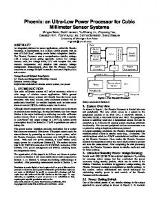
Sample Schematic A schematic is a drawing of an electronic circuit, showing the components graphically and how they are connected together. The following schematic has several annotations: ■
Names of components Each component is labeled with the name that appears in the instance statement for that component. The names for components are in italics (for example, Q2).
January 2004
26
Product Version 5.0
Spectre Circuit Simulator User Guide Getting Started with Spectre ■
Names of nodes Each node in the circuit is labeled with its unique name or number. This name can be either a name you create or a number. Names of nodes are in boldface type (for example, b1). Ground is node 0.
■
Sample instance statements
January 2004
27
Product Version 5.0
Spectre Circuit Simulator User Guide Getting Started with Spectre The schematic is annotated with instance statements for some of the components. Arrows connect the components in the schematic with their corresponding instance statements.
Bold Type = Names of nodes. All connections to ground have the same node name. Italic Type = Names of components (also appear in the instance statement for each component). = Link between components and instance statements.
∼
∼
Vcc
Vcc cc
cc
C1
L1 out
•
∼cc
Vcc C2 b1
b2
• Q1
•
e
Q2
•
R1
Iee C3
C4
R2
Q1 (cc b1 e) npn C3 (b1 0) capacitor c=3nF R1 (b1 0) resistor r=10k
Sample Netlist A netlist is an ASCII file that lists the components in a circuit, the nodes that the components are connected to, and parameter values. You create the netlist in a text editor such as vi or January 2004
28
Product Version 5.0
Spectre Circuit Simulator User Guide Getting Started with Spectre emacs or from one of the environments that support the Spectre simulator. The Spectre simulator uses a netlist to simulate a circuit. // BJT ECP Oscillator
Comment (indicated by //)
simulator lang=spectre
Indicates the file contains a Spectre netlist (see the next section). Place below first line.
Iee (e 0) isource dc=1mA Vcc (cc 0) vsource dc=5 Q1 Q2
(cc b1 e) npn (out b2 e) npn
L1
(cc out) inductor l=1uH
C1 C2 C3 C4
(cc out) capacitor c=1pf (out b1) capacitor c=272.7pF (b1 0) capacitor c=3nF (b2 0) capacitor c=3nF
R1 R2
(b1 (b2
Instance statements
0) resistor r=10k 0) resistor r=10k Control statement (sets initial conditions)
ic cc=5 model npn bjt type=npn bf=80 rb=100 vaf=50 \ cjs=2pf tf=0.3ns tr=6ns cje=3pf cjc=2pf
Model statement Analysis statement
OscResp tran stop=80us maxstep=10ns
Elements of a Spectre Netlist This section briefly explains the components, models, analyses, and control statements in a Spectre netlist. All topics discussed here (such as model statements or the simulator lang command) are presented in greater depth in later chapters. If you want more complete reference information about a topic, consult these discussions. Title Line The first line is taken to be the title. It is used verbatim when labeling output. Any statement you place in the first line is ignored as a comment. For more information about comment lines, see “Basic Syntax Rules” on page 59.
January 2004
29
Product Version 5.0
Spectre Circuit Simulator User Guide Getting Started with Spectre Simulation Language The second line of the sample netlist indicates that the netlist is in the Spectre Netlist Language, instead of SPICE. For more information about the simulator lang command, see Spectre Language Modes on page 59. Instance Statements The next section in the sample netlist consists of instance statements. To specify a single component in a Spectre netlist, you place all the necessary information for the component in a netlist statement. Netlist statements that specify single components are called instance statements. (The instance statement also has other uses that are described in Chapter 4, “Spectre Netlists.”) To specify single components within a circuit, you must provide the following information: ■
A unique component name for the component
■
The names of nodes to which the component is connected
■
The master name of the component (identifies the type of component)
■
The parameter values associated with the component
A typical Spectre instance statement looks like this:
Component name
R16 (4 0) resistor r=100
Node names
Parameter value
Master name
Note: You can use balanced parentheses to distinguish the various parts of the instance statement, although they are optional: R1 Q1 Gm R7
(1 (c (1 (x
2) resistor r=1 b e s) npn area=10 2)(3 4) vccs gm=.01 y) rmod (r=1k w=2u)
Component Names Unlike SPICE, the first character of the component name has no special meaning. You can use any character to start the component name. For example: January 2004
30
Product Version 5.0
Spectre Circuit Simulator User Guide Getting Started with Spectre Load (out o) resistor r=50 Balun (in o pout nout) transformer
Note: You can find the exact format for any component in the parameter listings for that component in the Spectre online help. Master Names The type of a component depends on the name of the master, not on the first letter of the component name (as in SPICE); this feature gives you more flexibility in naming components. The master can be a built-in primitive, a model, a subcircuit, or an AHDL component. Parameter Values Real numbers can be specified using scientific notation or common engineering scale factors. For example, you can specify a 1 pF capacitor value either as c=1pf or c=1e-12. Depending on whether you are using the Spectre Netlist Language or SPICE, you might need to use different scale factors for parameter values. Only ANSI standard scale factors are used in Spectre netlists. For more information about scale factors, see Instance Statements on page 62. Control Statements The next section of the sample netlist contains a control statement, which sets initial conditions. Model Statements Some components allow you to specify parameters common to many instances using the model statement. The only parameters you need to specify in the instance statement are those that are generally unique for a given instance of a component. You need to provide the following for a model statement: ■
The keyword model at the beginning of the statement
■
A unique name for the model (reference by master names in instance statements)
■
The master name of the model (identifies the type of model)
■
The parameter values associated with the model
January 2004
31
Product Version 5.0
Spectre Circuit Simulator User Guide Getting Started with Spectre The following example is a model statement for a bjt. The model name is npn¸ and the component type name is bjt. The backslash (\) tells you that the statement continues on the next line. The backslash must be the last character in the line because it escapes the carriage return. model npn bjt type=npn bf=80 rb=100 vaf=50 \ cjs=2pf tf=0.3ns tr=6ns cje=3pf cjc=2pf
When you create an instance statement that refers to a model statement for its parameter values, you must specify the model name as the master name. For example, an instance statement that receives its parameter values from the previous model statement might look like this: Q1
(vcc b1 e vcc) npn
Check documentation for components to determine which parameters are expected to be provided on the instance statement and which are expected on the model statement. Analysis Statements The last section of the sample netlist has the analysis statement. An analysis statement has the same syntax as an instance statement, except that the analysis type name replaces the master name. To specify an analysis, you must include the following information in a netlist statement: ■
A unique name for the analysis statement
■
Possibly a set of node names
■
The name of the type of analysis you want
■
Any additional parameter values associated with the analysis
To find the analysis type name and the parameters you can specify for an analysis, consult the parameter listing for that analysis in the Spectre online help (spectre -h). The following analysis statement specifies a transient analysis. The analysis name is stepResponse, and the analysis type name is tran. stepResponse tran stop=100ns
Instructions for a Spectre Simulation Run When you complete a netlist, you can run the simulation with the spectre command. ➤
To run a simulation for the sample circuit, type the following at the command line: spectre osc.scs
January 2004
32
Product Version 5.0
Spectre Circuit Simulator User Guide Getting Started with Spectre Note: osc.scs is the file that contains the netlist.
Following Simulation Progress As the simulation runs, the Spectre simulator sends messages to your screen that show the progress of the simulation and provide statistical information. In the simulation of osc.scs, the Spectre simulator prints some warnings and notifications. The Spectre simulator tells you about conditions that might reduce simulation accuracy. When you see a Spectre warning or notification, you must decide whether the information is significant for your particular simulation.
Screen Printout The printout for the osc.scs simulation looks like this: spectre (ver. 5.0.0.052603 -- 27 May 2003). Simulating `osc.scs' on cds11047 at 1:21:54 PM, Wed Aug 20, 2003. Circuit inventory: nodes equations bjt capacitor inductor isource resistor vsource
5 9 2 4 1 1 2 1
*************************************************** Transient Analysis `OscResp': time = (0 s -> 80 us) *************************************************** Narration of transient analysis progress
.....9.....8......7......6......5......4......3......2.....1......0 Number of accepted tran steps = 23508. Initial condition solution time = 0 s. Intrinsic tran analysis time = 7.07 s. Total time required for tran analysis `OscResp' was 7.08 s. Aggregate audit (1:22:02 PM, Wed Aug 20, 2003): Time used: CPU = 7.29 s, elapsed = 8 s, util. = 91.1%. Virtual memory used = 1.3 Mbytes. spectre completes with 0 errors, 0 warnings, and 0 notices
January 2004
33
Product Version 5.0
Spectre Circuit Simulator User Guide Getting Started with Spectre
Viewing Your Output The waveform display tool for this simulation example is WaveScan, a display tool you receive when you purchase the Spectre simulator. In this section you will learn the following: ■
How to start WaveScan
■
How to plot signals
■
How to change the color of a trace
Starting WaveScan ➤
Type the following at the command line: wavescan &
Note: To start WaveScan for the simulation example, type the following at the command line (from the directory where the Spectre simulator was run): wavescan -dataDir osc.raw
The Results Browser window appears with the osc.raw data directory displayed in the right panel.
January 2004
34
Product Version 5.0
Spectre Circuit Simulator User Guide Getting Started with Spectre
Plotting Signals 1. In the Results Browser window, double-click on osc.raw. The data directory moves to the left panel and the associated signals are displayed in the right panel.
January 2004
35
Product Version 5.0
Spectre Circuit Simulator User Guide Getting Started with Spectre 2. Right-click on the signal you want to plot (for example, out) and choose New Win from the pop-up menu. The Graph Display window appears.
3. Choose Zoom – X-Zoom. The
cursor is displayed on the Graph Display window.
4. Left-click at around 70us and, drag, and release the mouse button at around 80us.
January 2004
36
Product Version 5.0
Spectre Circuit Simulator User Guide Getting Started with Spectre The graph is zoomed such that 70us and 80us are the end points of the X-axis.
5. Click Zoom – Fit to return the graph to the unzoomed state.
Changing the Trace Color To change the color of the trace, 1. Double-click on the trace.
January 2004
37
Product Version 5.0
Spectre Circuit Simulator User Guide Getting Started with Spectre The Trace Attributes dialog box appears.
2. In the Foreground field, select the color for the trace. 3. Click OK.
Learning More about WaveScan The WaveScan display tool gives you a number of additional options for displaying your data. To learn more about using WaveScan, see the WaveScan User Guide.
January 2004
38
Product Version 5.0
Spectre Circuit Simulator User Guide Getting Started with Spectre
January 2004
39
Product Version 5.0
Spectre Circuit Simulator User Guide Getting Started with Spectre
January 2004
40
Product Version 5.0
Spectre Circuit Simulator User Guide
3 SPICE Compatibility While SPICE is an industry-standard language, there are many variations of SPICE syntax on the market today. Most of the language is common across the major commercial simulators, but each vendor has extended or modified it with different capabilities and/or slightly different syntax. For the convenience of SPICE users, the Spectre® circuit simulator provides a SPICE Reader as an extension to its native language that accepts most variations of SPICE input. The SPICE Reader provides support for SPICE2, SPICE3, and common extensions found in other simulators such as PSPICE and HSPICE. This chapter focuses on how to use the SPICE Reader with Spectre. This chapter is not intended to describe the syntax variations of SPICE, as they are well documented in other places, nor an exact listing of syntax supported by the SPICE Reader. ■
Reading SPICE Netlists on page 42
■
Language Differences on page 48
■
Scope of the Compatibility on page 51
January 2004
41
Product Version 5.0
Spectre Circuit Simulator User Guide SPICE Compatibility
Reading SPICE Netlists Spectre provides the SPICE Reader to let you simulate existing SPICE netlists with Spectre. While it is possible to gain access to many of Spectre’s features with a SPICE netlist, the Spectre syntax is a much more powerful language designed to give the Spectre user features beyond those provided by SPICE. Whenever possible, you are encouraged to take advantage of Spectre’s native language. When Spectre syntax is not an acceptable solution, the SPICE Reader can be used to ensure access to as much of Spectre’s capabilities as possible.
Running the SPICE Reader In order for Spectre to properly process a SPICE netlist, the SPICE Reader must be enabled. By default the SPICE Reader is disabled when you invoke Spectre. Use the command spectrespp rather than the spectre command to enable the SPICE Reader. For example, the following command invokes Spectre with the SPICE Reader for the input netlist amp.sp: spectrespp amp.sp
The Spice Reader runs on the top-level netlist, as well as on any included files that contain SPICE syntax. The SPICE Reader converts the netlist to Spectre native syntax before it sends the design to the Spectre netlist reader. From the 5.0 release, any .measure statements found in the Spice input file are converted to MDL (Measurement Description Language) before being passed on to Spectre. The conversion is done via the creation of an MDL control file, which is written to the current directory. This control file takes on the name of the netlist, with a suffix of .mdl. The simulation that immediately follows the conversion uses the MDL option to Spectre with this control file to evaluate the .measure expressions. Results are written to a file with the same name as the control file (netlist) with a .measure suffix. For example, the amp.sp SPICE netlist above creates a control file named amp.mdl, and a measurement output file named amp.measure. You simply enter the spectrespp command with the netlist, and the rest of the steps are completed for you automatically. The MDL control file is left behind for future use. Note: In previous releases, the command line option +spp was used to invoke the SPICE Reader. While this method is still supported, it is advised that you use the spectrespp command if .measure statements are included in the input file. For more information on MDL, see the SpectreMDL User Guide and Reference. For backward compatibility, a limited SPICE2 netlist reader is embedded into the Spectre netlist reader. This reader supports much of SPICE2G6 syntax and has as its primary use the processing of SPICE-style model cards. If the SPICE Reader is not used, this limited SPICE netlist reader is used. This is only for backwards compatibility and might be removed in a future release, to be replaced by the SPICE Reader. This limited SPICE netlist reader is no longer documented as of the 4.4.3 release. In the rest of this chapter, “SPICE Reader” refers to the full SPP SPICE Reader, and not this limited version. January 2004
42
Product Version 5.0
Spectre Circuit Simulator User Guide SPICE Compatibility
Running the SPICE Reader from Cadence Analog Design Environment When using Spectre within Cadence Analog Design Environment, the need to read SPICE netlists is usually limited to model files and information from extraction tools that comes into the netlist by included files. For all other design data, Analog Artist produces netlists in the Spectre native syntax. You can enable the use of the SPICE Reader by choosing the Setup -> Environment form and toggling the Use SPICE Netlist Reader (spp) button to Y. Be sure that you do not have any relative paths specified for included files, such as model files, and that the Include Path field in the Setup -> Simulation Files field is blank. The SPICE Reader’s inability to handle relative paths is documented in the Spectre Known Problems and Solutions.
Running the SPICE Reader from the Command Line When you run Spectre from the command line (outside of the Artist/Composer environment), the SPICE Reader is disabled by default. As described in “Running the SPICE Reader” on page 42, you must use the spectrespp command for the SPICE Reader to process the toplevel netlist: spectrespp opamp.sp
This command calls Spectre with the spp and mdl command line options. There are several command line options that can be used in conjunction with spectrespp: Specifying the Design File The command line option -design is used to identify the input file. In the absence of any command line options, the single argument after the spectrespp command is assumed to be the input netlist. Therefore the following commands are identical: spectrespp opamp.sp spectrespp -design opamp.sp
Specifying the spp Binary to be Used By default, the spp binary that is located in the Cadence hierarchy, your_install_directory/tools/dfII/bin/spp,is used by the spectrespp command. You can specify the use of other spp executables with the -sppbin command line option. In the following example, spp from the current directory is used: spectrespp -sppbin ./spp opamp.sp
January 2004
43
Product Version 5.0
Spectre Circuit Simulator User Guide SPICE Compatibility Specifying the Location of the Measurement Output The command line option -measure is used to specify the location of the measurement output. The following command spectrespp -measure design.measure -design opamp.sp
writes the output to design.measure. If you do not use this option, the output of the .measure statement is written to a file with the same base name as the netlist and the suffix .measure. In the above example, this would be opamp.measure. Notice that when specifying the -measure option, you must also specify the -design option to identify the netlist. All other command line options are passed to Spectre. Type spectrespp -usage for online help.
Using the SPICE Reader to Convert Netlists In many cases, the SPICE data to be used with Spectre is a library of models or reusable blocks (that is, subcircuits). Rather than using the SPICE Reader to interpret these files each time they are used, you can convert the netlist to Spectre’s native syntax. This is done by running the SPICE Reader alone (spp) and using the -convert option. The -convert option removes special embedded codes for tracking the line numbers of the original netlist, returning a cleanly converted netlist. spp -convert -iofile inputFile [outputFile]
or spp -convert < inputFile [ > [outputFile] ]
where spp
Runs the SPICE reader.
-convert
Converts the SPICE netlist to an equivalent Spectre netlist. This option does not descend into included files to convert them but only converts the include statement. Included files must be converted independently. In this case, the SPICE Reader cannot always resolve conflicts and ambiguities, and you must verify the resulting netlist files.
January 2004
44
Product Version 5.0
Spectre Circuit Simulator User Guide SPICE Compatibility
-iofile
Replaces all instances of the input file name (in include statements) with the output file name in the converted netlist. Do not put < > around the input file name if you use this option.
inputFile
The SPICE netlist to be converted. Put < > around the input file name only if you do not use the iofile option.
outputFil
The file name for the converted netlist. If you do not specify this, the converted netlist is displayed at standard output — i.e., in the terminal window.
Examples The following command converts the SPICE netlist amp.sp to an equivalent Spectre netlist and displays the result in the terminal window: spp -convert < amp.sp
The following command converts the SPICE netlist amp.sp to an equivalent Spectre netlist with the name amp.scs: spp -convert < amp.sp > amp.scs
The following command converts the SPICE netlist amp.sp to an equivalent Spectre netlist with the name test.scs. All references to amp.sp in the input file are replaced by test.scs in the output file. spp -convert -iofile amp.sp test.scs
Converting Hierarchically Arranged Netlists Great care must be taken when converting hierarchically arranged netlists. Some of the possible issues include the following: ■
Distinguishing instance models from instance parameters For some devices, such as resistors, SPICE instance statements can use an orderdependent mechanism to define the values of parameters. An example could be r1 1 0 myres
The field myres could be either a model name or a parameter representing the resistance value in SPICE. The SPICE Reader maps this to a parameter if a .param statement is encountered with this assignment or to a model name if a model card with the name myres is found. If neither is present, the field is assumed to be a model name. In the case of the -convert mode, where these assignments could be part of included January 2004
45
Product Version 5.0
Spectre Circuit Simulator User Guide SPICE Compatibility files, this assumption could be incorrect, and the instance statement would need to be fixed. ■
Global nodes In Spectre, global nodes must be at the very beginning of the netlist, while they can be present anywhere in a SPICE netlist. If a converted file contains global nodes, these must be moved to the top level of the netlist before the file can be included in a higher level netlist. Multiple global statements cause fatal errors in Spectre.
■
Location of measurement data The SPICE Reader converts Hspice style .measure statements to Measurement Description Language (MDL) statements. The SPICE Reader does this by creating an MDL control file, which can then be used in the simulation. In normal operation (using the spectrespp command), the control file that is created takes on the name of the netlist, with the suffix .mdl. When a netlist is converted with the -convert option, the MDL control file that is created is always named Netlist.mdl. If this control file is used in a subsequent simulation, the results output is written to a file named Netlist.measure. For example, say that you have an SPICE netlist named amp.sp. In order to convert this netlist without executing the simulation, use spp with the -convert option: spp -convert < amp.sp > amp.scs
Upon completion of this command, the Spectre equivalent for amp.sp is in the amp.scs file. In addition, a file called Netlist.mdl is created. This additional file contains the MDL expressions that correspond to any .measure statements in the original netlist. In order to run the Spectre simulation using the new netlist and control file, use the following command: spectremdl -batch Netlist.mdl -design amp.scs
Upon completion of the simulation, you’ll find a file named Netlist.measure, which contains the values calculated for each of the MDL expressions. For more information on the expression evaluation capabilities in Spectre, see the SpectreMDL User Guide and Reference. ■
Netlist parameters In Spectre, parameters are order dependent; that is, they must be defined before being used. When the SPICE Reader is run on the entire design, parameters are moved to the top of the netlist, but, in convert mode, they are moved to the top of each file. If a parameter is accessed before inclusion, it will fail until it is fixed.
■
Order-dependent statements
January 2004
46
Product Version 5.0
Spectre Circuit Simulator User Guide SPICE Compatibility Some statements in SPICE are mapped into multiple statements in Spectre. Things like temp sweeps, analysis sweeps, and alter sections all get converted into multiline statements. If temp statements, analysis statements, or alter statements are not in the same file, they might not get properly unfolded. Here is an example of a Mos characterization deck written in SPICE: M1 1 2 0 0 NCH VDR 1 0 2 VG 2 0 1 .OP .MODEL NCH NMOS LEVEL=49 + TOX=1e-9 VTH0=0.5 VBOX=5 .TEMP 25 75 100 .INCLUDE "dcAnalysis.inc" .END
where dcAnalysis.inc is .DC VDR 0 5 0.1 VG 0 2 0.1
The netlist produced with spp -convert does not include the sweep statement within the temperature sweep: // Mos characterization deck simulator lang=spectre insensitive=yes m1 ( 1 2 0 0 ) nch vdr ( 1 0 ) vsource dc=2 vg ( 2 0 ) vsource dc=1 model nch bsim3v3 type=n tox=1e-9 vth0=0.5 vbox=5 include "dcAnalysis.inc" swp_tmp1 sweep param=temp values=[25 75 100] { sppSaveOptions options save=allpub analysisOP1 dc oppoint=logfile } // end
You need to edit the netlist to insert the included analysis into the temperature sweep: // Mos characterization deck simulator lang=spectre insensitive=yes m1 ( 1 2 0 0 ) nch vdr ( 1 0 ) vsource dc=2 vg ( 2 0 ) vsource dc=1 model nch bsim3v3 type=n tox=1e-9 vth0=0.5 vbox=5 swp_tmp1 sweep param=temp values=[25 75 100] { sppSaveOptions options save=allpub analysisOP1 dc oppoint=logfile analysisDCswp1 sweep param=dc dev=vg start=0 stop=2 step=0.1 { analysisDCswp2 dc param=dc dev=vdr start=0 stop=5 step=0.1 } } // end ■
Mixed language Spectre allows the use of both SPICE and Spectre syntax in the same netlist. The SPICE Reader does not read the Spectre statements; thus, statements in the SPICE sections
January 2004
47
Product Version 5.0
Spectre Circuit Simulator User Guide SPICE Compatibility that are dependent on Spectre statements might get improperly mapped. Except for model and subcircuit names, do not have any dependencies between these two language sections.
Language Differences Comparing the SPICE and Spectre Languages When you run the SPICE Reader, all SPICE statements are mapped directly to Spectre input. There are several important differences between these two languages that are addressed by the SPICE Reader. To get a better idea at the differences between the two languages, an example netlist is shown below. First is the SPICE version of the netlist for an oscillator (from “Sample Netlist” on page 28): BJT ECP Oscillator Vcc 1 0 5 Iee 2 0 1MA Q1 1 3 2 NPN Q2 4 5 2 NPN L1 4 5 1UH C1 1 5 1PF C2 5 3 272.7PF C3 3 0 3NF C4 5 6 3NF R1 3 0 10K R2 5 6 10K .ic V(3)=1 .model NPN NPN BF=80 RB=100 + VAF=50 CJS=2PF TF=0.3NS TR=6NS CJE=3PF CJC=2PF .option method=trap .tran 1us 80us 10ns Here is the Spectre version of the same netlist: // BJT ECP Oscillator simulator lang=spectre Vcc (vcc 0) vsource dc=5 Iee (e 0) isource dc=1mA Q1 (vcc b1 e) npn Q2 (out b2 e) npn L1 (vcc out) inductor l=1uH C1 (vcc out) capacitor c=1pf C2 (out b1 ) capacitor c=272.7pF C3 (b1 0) capacitor c=3nF C4 (b2 in ) capacitor c=3nF R1 (b1 0) resistor r=10k R2 (b2 in ) resistor r=10k
January 2004
48
Product Version 5.0
Spectre Circuit Simulator User Guide SPICE Compatibility ic b1=1 model npn bjt type=npn bf=80 rb=100 vaf=50 \ cjs=2pf tf=0.3ns tr=6ns cje=3pf cjc=2pf OscResp tran stop=80us maxstep=10ns method=trap
This example shows several of the basic differences between SPICE and Spectre netlists: ■
Spectre netlists define the language context at the beginning of the netlist with the simulator lang=spectre statement. By default, netlists are assumed to be in SPICE unless the simulator lang=spectre statement is encountered or unless the netlist file ends in the extension .scs. The SPICE Reader will insert this line at the beginning of each SPICE-to-Spectre converted netlist.
■
In the SPICE language, the component type is determined by the first letter of the component name, which limits the component types to 26. The Spectre Netlist Language has unlimited component types since the component type is determined by the master name instead of the first letter of the component name. An example of using the master name is the resistor field in the instance statements for R1 and R2.
■
In many versions of SPICE, the component name, node numbers, and other fields are limited to a maximum of 8 characters. The Spectre netlister allows each of these fields to be greater than 200 characters.
■
In the SPICE language, instance statements often have their parameter values listed in a particular order. In the Spectre language, you can specify parameter values in any order using parameter name =. This allows for a more readable netlist.
■
Spectre netlists are case sensitive and use lower case for all keywords. SPICE netlists are case insensitive. This means that you can name one model myModel and another mymodel, and Spectre treats them as two distinct models. In SPICE, they would be considered to be the same model. Spectre always tries to match the case of a model/subcircuit’s name when there is a call to a model/subcircuit from an instance line, an alter statement, or other part of the netlist. During the netlist conversion process, the SPICE Reader converts included models/subcircuits to lower case, which can prevent Spectre from identifying the right model/subcircuit for a given device. For this reason, the SPICE Reader will insert the flag insensitive=yes at the beginning of each converted netlist on the simulator command statement (that is, simulator lang=spectre insensitive=yes). The insensitive=yes language directive marks the models/subcircuits that were converted so that Spectre can perform a lower case compare.
■
Because the SPICE language is case insensitive, the scale factors are different from the Spectre scale factors (see “Scaling Numerical Literals” on page 83 for more information). The Spectre Netlist Language uses the ANSI standard (SI) scale factors.
January 2004
49
Product Version 5.0
Spectre Circuit Simulator User Guide SPICE Compatibility ■
Options that are analysis specific are found on the global .options card in SPICE. In Spectre, options pertaining to an analysis are listed on the analysis card.
■
Spectre supports the idea of named analyses, which allows you to include multiple analyses of the same type in a single netlist. The SPICE Reader takes advantage of Spectre’s ability to have more than one analysis of each type, mapping each analysis statement to the equivalent Spectre analysis and providing each a unique name. If multiple analysis of the same type are listed within the SPICE deck, each will be simulated instead of the “last one wins” mode of SPICE
■
In both Spectre and Spice, the first line is always the title card and ignored by the simulator.
■
A card (other than the title or a comment) can be continued onto the next card by putting the continuation character (+) in the first column of the next card. Spectre also supports continuations at the end of the line in its native mode, with the backslash character (\).
■
In many versions of Spice, there are punctuation characters (such as parentheses and commas) that are treated as white space. Spectre will treat all characters as relevant input. The SPICE Reader will treat all of these characters as literals.
■
The Spectre simulator does not require an .end statement; it assumes the end of the input file is the end of the input statements. The .end statement, if included in a SPICE netlist, is treated like the end of file; and the SPICE Reader does not read beyond the .end.
Reading SPICE and Spectre Files When the Spectre simulator opens a netlist file, the simulator determines whether the file is a SPICE or Spectre netlist and interprets it accordingly. This is true regardless of whether the file is the main netlist or an included netlist. The Spectre simulator recognizes Spectre files because they start with the line simulator lang=spectre or the filename ends in the Spectre circuit simulator extension of .scs. Files that do not start with this line or end in the .scs extension are taken to be SPICE files. Thus, SPICE files do not need to be modified to work with the Spectre simulator as the SPICE Reader will automatically map them correctly to Spectre input. The .scs extension allows users to write netlists, included files, and library files using only the Spectre Netlist Language without having to switch from SPICE mode. To learn more about controlling the input language, see “General Input Compatibility” on page 51.
January 2004
50
Product Version 5.0
Spectre Circuit Simulator User Guide SPICE Compatibility
Scope of the Compatibility Many current variants of SPICE have their own alterations to the SPICE input language. The SPICE Reader in Spectre does support many of these variations using the following sources and guidelines.
Sources ■
The SPICE Version 2G User’s Guide [vladimirescu81] is the reference for the SPICE2 input language. The SPICE Reader accepts input formats from this document for all SPICE capabilities the Spectre simulator supports. The SPICE Reader might not accept variations from SPICE 2G6 that are not in the user guide.
■
The SPICE3 Version 3e User’s Manual [B.JohnsonXX] is the reference for SPICE3 batch input language. The SPICE Reader accepts input formats (batch mode only) from this document for all SPICE capabilities the Spectre simulator supports.
■
The SPICE BOOK [vladimirescu81] is a general reference for SPICE2/3-based syntax’s with common extensions.
■
Publicly available netlists provide references for many of the extensions to SPICE.
Compatibility Guidelines ■
Mapping of SPICE must not adversely affect simulation results.
■
Where simulators follow different syntax rules, support for each is attempted. For example, the TC property is an instance property in SPICE2 and model parameters (TC1,TC2) in SPICE3—both are supported.
■
When a conflict exists between simulator syntax rules, one method is selected and documented.
General Input Compatibility By default, the SPICE Reader processes its input in the following manner: ■
Accepts the SPICE instance (A-Z) and control (dot) cards as well as the Spectre native input language.
■
Reads in the first line as the title card.
January 2004
51
Product Version 5.0
Spectre Circuit Simulator User Guide SPICE Compatibility ■
Generally ignores the case of alphabetic characters in the input (The program internally converts them to lowercase). Quoted strings are exceptions to this rule.
■
Interprets scale factors following numerical values according to SPICE conventions.
■
Accepts the SPICE comment and continuation conventions.
■
Accepts the /, +, -, and * characters as valid parts of a node or an instance or parameter name. You can also use the Escape backslash convention to include otherwise illegal characters in the names.
■
Spectre statements are not allowed in the SPICE mode, and SPICE statements are not allowed in the Spectre mode.
■
In simulator lang=spectre mode, you can refer to model names and subcircuit names defined with the simulator lang=spice mode .model and .subckt statements, even though they are in another portion of the netlist. Spectre always tries to match the case of a model/subcircuit’s name when there is a call to a model/subcircuit from an instance line, an alter statement, or other part of the netlist. During the netlist conversion process, the SPICE Reader converts included models/subcircuits to lower case, which can prevent Spectre from identifying the right model/subcircuit for a given device. For this reason, the SPICE Reader will insert the flag insensitive=yes at the beginning of each converted netlist on the simulator command statement (that is, simulator lang=spectre insensitive=yes). The insensitive=yes language directive marks the models/subcircuits that were converted so that Spectre can perform a lower case compare.
■
The SPICE Reader treats the * character as a math function if found inside of an expression and as a comment if found outside of an expression.
■
Lines beginning with #CPP keywords are not treated as comments by the SPICE Reader but will result in an syntax error unless you run CPP on the netlist.
■
You can force the SPICE Reader to treat all bjt devices as having four terminals with the -q4term command line option to spp. By default, the fourth field after the device name of an instance statement is treated as a terminal, unless one of the following occurs: ❑
There is a model name within the netlist that is named the same as the fourth field.
❑
It is the last item on the instance line.
For example: q1 1 2 3 4 mybjt // The 4 is treated as a device terminal q1 1 2 3 nch mybjt
The nch is treated as a device terminal unless
January 2004
52
Product Version 5.0
Spectre Circuit Simulator User Guide SPICE Compatibility ❑
mybjt is defined as a parameter in the netlist
❑
nch is defined as a model in the netlist
In the second case, the -q4term option can be used to override the default behavior of the converter. You can gain full access to Spectre and its features with a SPICE netlist by controlling the input language. Spectre provides three ways to gain access to its language in a SPICE netlist: 1. Change the input language to Spectre using the simulator lang command 2. Append Spectre parameters to a SPICE statement 3. Hide Spectre text from SPICE Each of these methods is discussed in the following sections. Spectre’s simulator lang Command You can use the Spectre Netlist Language or an extended form of the SPICE2/3 input language for your simulation. You specify which language with a simulator lang command. You can change the input-processing mode with the simulator lang command. A simulator lang=spice command causes subsequent input to be processed in the SPICE extension mode; a simulator lang=spectre command causes the input processing to conform to the Spectre Netlist Language. (Remember that you can give the simulator lang command anywhere that you can enter an instance statement, and it affects all subsequent input regardless of whether the command is part of an if statement.) Use of Spectre syntax in the SPICE mode or SPICE syntax in the Spectre mode results in an error. The fomat of the simulator lang command is as follows: simulator lang=spice simulator lang=spectre
Although the simulator lang command is expected to be the first line in the netlist, it does not have to be. The commands take effect immediately and remain in effect until the end of input or until the next simulator lang command. For example, you can include Spectre lines in the middle of a SPICE netlist by surrounding the Spectre lines with the simulator lang command: r1 1 0 1k v1 1 0 1
January 2004
53
Product Version 5.0
Spectre Circuit Simulator User Guide SPICE Compatibility simulator lang=spectre r2 1 0 resistor r=1k simulator lang=spice .op
If you do not specify an input language, the Spectre simulator uses SPICE mode by default. You do not need to place simulator lang commands around include statements, but you must specify simulator lang=spectre in include files written in the Spectre Netlist Language. Spectre allows you to specify the netlist input format to be Spectre without the simulator lang command by naming the file with the Spectre circuit simulator extension of .scs. Files ending in this extension are treated as Spectre syntax. Appending Spectre Parameters While you can gain full access to Spectre features by switching to the Spectre syntax, you can also gain access to specific parameters on the SPICE input statements. The SPICE Reader maps each SPICE statement to the Spectre equivalent statement. Mapping of parameters is done first for order-dependent parameters and then for name=value based parameters. The SPICE reader tries to map parameters in the name=value form if they are known; otherwise, they are passed directly to Spectre as is. This allows you to add Spectre parameters to the end of any SPICE statement. For example, * Additional Spectre parameter to resistor Vin input 0 dc=1 AC 1 0 X1 mainnetlist in out Rload out 0 1k isnoisy=no //isnoisy is spectre parameter .include “./main.ckt” .ac dec 10 1k 100k .noise v(out) .end
If the netlist is to be run by a SPICE simulator at a later time, these Spectre parameters must be hidden or removed. See the next section for information on how to hide Spectre text. Hiding Spectre Text from SPICE You can create a SPICE-mode input file that you can use with both a SPICE-based simulator and the Spectre simulator. When you run the Spectre simulator, you can use Spectre features unavailable in SPICE. For example, if you want to specify a Spectre parameter that SPICE does not support, you write the Spectre statements so they do not cause syntax errors when you run the SPICE-based simulator. To create such an input file, follow these steps: 1. Insert the special prefix *spectre: at the beginning of a line in your SPICE netlist.
January 2004
54
Product Version 5.0
Spectre Circuit Simulator User Guide SPICE Compatibility The line should start with an asterisk, optionally followed by blanks or tabs, followed by the string spectre: . * spectre: (Spectre text)
Be sure to leave a space after the colon. 2. Place Spectre-specific input language statements after the : Notepecial prefix. The Spectre simulator recognizes the Spectre statements after the prefix as input, but the SPICE-based simulator ignores the whole line as a comment. *spectre: Rp 15 0 resistor r=50m
Note: These statements must be in the Spectre context of a netlist. 3. If you need to place the Spectre input in continuation lines, begin each line of a continuation with a (+). Vbias vbb 0 1.2 *spectre: + tc=0.001 .options reltol=0.001 *spectre: + diagnose=yes
Compatibility Limitations Conflicts between Spectre and Spice ■
The Spectre simulator does not support all SPICE capabilities (for example, the .disto and .PZ analyses).
■
Slight modifications are often necessary to make input acceptable to both languages. Superficial punctuation differences, such as ignoring extra parentheses or equal signs (=), fit this category. For example, the statement .temp = 125, which is legal in SPICE, cannot be mapped by the SPICE Reader. Removing the extraneous punctuation solves the problem.
■
Compatibility is limited in the area of unsupported primitive devices in Spectre. You are encouraged to use the extensive capabilities of Verilog-A to model such devices.
■
Parameters that are to be passed into a subcircuit from an instance statement must be specified on the SPICE subcircuit line. Allowing the instance to define a subcircuit parameter is not allowed in Spectre.
■
Incompatibilities remain for some rarely used SPICE2 features because the authors have concentrated their efforts on creating compatibility with commonly used features.
January 2004
55
Product Version 5.0
Spectre Circuit Simulator User Guide SPICE Compatibility Conflicts between SPICE variations ■
Node 00 is treated as a number (that is, zero) in SPICE2 and a string (that is, 00) in SPICE3 and thus are interpreted differently. The SPICE Reader treats these like SPICE3.
■
Leading spaces are ignored in SPICE2 and treated as a comment in SPICE3. The SPICE Reader treats these as SPICE2 does.
■
.lib in PSPICE provides a file to search for each instantiated model; in HSPICE, it acts as a section-specific include statement. The SPICE Reader treats these as HSPICE does.
■
.alter in SPICE2 allows multiple lines to be relisted with deltas following this statement. In SPICE3, the .alter is an interactive command and only allows one parameter to be changed per alter statement. The SPICE Reader treats these as SPICE2 does.
■
In some versions of SPICE, global parameters values override values specified on instances of subcircuits. The SPICE Reader treats all parameter values specified on any instance including subcircuits as the final value instead of allowing a global to override it.
For more information on specific SPICE Reader limitations, please see the SPP Known Problems and Solutions on SourceLink.
January 2004
56
Product Version 5.0
Spectre Circuit Simulator User Guide
4 Spectre Netlists This chapter discusses the following topics: ■
Netlist Statements on page 58
■
Instance Statements on page 62
■
Analysis Statements on page 66
■
Control Statements on page 68
■
Model Statements on page 70
■
Input Data from Multiple Files on page 72
■
Multidisciplinary Modeling on page 76
■
Inherited Connections on page 78
January 2004
57
Product Version 5.0
Spectre Circuit Simulator User Guide Spectre Netlists
Netlist Statements A Spectre® circuit simulator netlist describes the structure of circuits and subcircuits by listing components, the nodes that the components are connected to, the parameter values that are used to customize the components, and the analyses that you want to run on the circuit. You can use SpectreHDL or Verilog®-A to describe the behavior of new components that you can use in a netlist like built-in components. You can also define new components as a collection of existing components by using subcircuits. A netlist consists of four types of statements: ■
Instance Statements on page 62
■
Analysis Statements on page 66
■
Control Statements on page 68
■
Model Statements on page 70
Before you can create statements for a Spectre netlist, you must learn some basic syntax rules of the Spectre Netlist Language.
Netlist Conventions These are the netlist conventions followed by the Spectre simulator. Associated Reference Direction The reference direction for the voltage is positive when the voltage of the + terminal is higher than the voltage of the – terminal. A positive current arrives through the + terminal and leaves through the – terminal.
Current + Voltage -
January 2004
58
Product Version 5.0
Spectre Circuit Simulator User Guide Spectre Netlists Ground Ground is a common reference point in an electrical circuit. The value of ground is zero. Node A node is an infinitesimal connection point. The voltage everywhere on a node is the same. According to Kirchhoff’s Current Law (also known as Kirchhoff’s Flow Law), the algebraic sum of all the flows out of a node at any instant is zero.
Basic Syntax Rules The following syntax rules apply to all statements in the Spectre Netlist Language: ■
Field separators are blanks, tabs, punctuation characters, or continuation characters.
■
Punctuation characters such as equal signs (=), parentheses (()), and colons (:) are significant to the Spectre simulator.
■
You can extend a statement onto the next line by ending the current line with a backslash (\). You can use a plus sign (+) to indicate line continuation at the beginning of the next line. The preferred style is the \ at the end of the line.
■
You can indicate a comment line by placing a double slash (//) at the beginning of the comment. The comment ends at the end of that line. You can also use an asterisk (*) to indicate a comment line. The preferred style is using //.
■
You can indicate a comment for the remainder of a line by placing a space and double slash (//) anywhere in the line.
Spectre Language Modes The Spectre netlist supports two language modes: ■
Spectre mode (mostly discussed here)
■
SPICE mode
You can specify the language mode for subsequent statements by specifying simulator lang=mode, where mode is spectre or spice. Spectre mode input is fully case sensitive. In contrast, except for letters in quoted strings, SPICE mode converts input characters to lowercase.
January 2004
59
Product Version 5.0
Spectre Circuit Simulator User Guide Spectre Netlists
Creating Component and Node Names When you create node and component names in the Spectre simulator, follow these rules. ■
Do not use the name of an analysis (such as tran) or built-in primitive (such as resistor).
■
Except for node names, names must begin with a letter or underscore. Node names can also be integers.
■
If the node name is an integer, leading zeros are significant in the Spectre language mode.
■
Names can contain any number of letters, digits, or underscores.
■
Names cannot contain nonalphanumeric characters, blanks, tabs, punctuation characters, or continuation characters (\, +, -, //, *) unless they are escaped with a backslash (\). The exception is bang (!), for example, vdd!.
■
The following reserved words (case specified) should not be used as node names, net names, instance names, model names, or parameter names.
M_1_PI
M_2_PI
M_2_SQRTPI
M_DEGPERRAD
M_E
M_LN10
M_LN2
M_LOG10E
M_LOG2E
M_PI
M_PI_2
M_PI_4
M_SQRT1_2
M_SQRT2
M_TWO_PI
P_C
P_CELSIUS0
P_EPS0P_H
P_K
P_Q
P_U0
abs
acos
acosh
altergroup
asin
asinh
atan
atan2
atanh
ceil
correlate
cos
cosh
else
end
ends
exp
export
floor
for
function
global
hypot
ic
if
inline
int
library
local
log
log10
march
max
min
model
nodeset
parameters
paramset
plot
January 2004
60
Product Version 5.0
Spectre Circuit Simulator User Guide Spectre Netlists
pow
print
pwr
real
return
save
sens
sin
sinh
sqrt
statistics
subckt
tan
tanh
to
truncate
vary
Multiple Namespace From release 5.0.32 onwards, you need not have unique names for device instances, models, nets, subcircuit parameters, enumerated named values for parameters, and netlist parameters that are expressions. Consider the following example: simulator lang=spectre parameters c1=1p c2=2p c10=c1+c2 parameters res=10k res c10 0 resistor r=res c10 c10 0 capacitor c=c10 run dc spectre2 options currents=all
res is used as a parameter and instance name. c10 is used as a node, instance, and parameter name. The Spectre circuit simulator can now read this netlist. The Spectre circuit simulator can resolve ambiguous statements as shown in the example below: parameters xyz=1 xyz 1 0 vsource dc=xyz h1 3 0 ccvs probe=xyz rm=xyz
The Spectre circuit simulator assigns the instance xyz to probe and the parameter xyz to rm. In the example below, vcc vcc 0 vsource dc=1 save vcc
the Spectre circuit simulator saves the node vcc rather than the instance vcc. If you want to save the instance vcc, you must assign a different name to it.
January 2004
61
Product Version 5.0
Spectre Circuit Simulator User Guide Spectre Netlists
Escaping Special Characters in Names If you have old netlists that contain names that do not follow Spectre syntax rules, you might still be able to run these netlists with the Spectre simulator. The Spectre Netlist Language permits the following exceptions to its normal syntax rules to accommodate old netlists. Use these features only when necessary. If you place a backslash (\) before any printable ASCII character, including spaces and tabs, you can include the character in a name. You can create a name from the following elements in the order given: A string of digits, followed by ❑
Letters, underscores, or backslash-escaped characters, followed by
❑
A digit, followed by
❑
Underscores, digits, or backslash-escaped characters
This accommodates model or subcircuit libraries that use names like \2N2222.
Instance Statements In this section, you will learn to place individual components into your netlist and to assign parameter values for them.
Formatting the Instance Statement To specify components, you use the instance statement. You format the instance statement as follows: name [(]node1 ... nodeN[)] master [[param1=value1] ...[paramN=valueN]]
When you specify components with the instance statement, the fields have the following values: name
January 2004
The name you give to the statement. (Unlike SPICE instance names, the first character in Spectre instance names is not significant.)
62
Product Version 5.0
Spectre Circuit Simulator User Guide Spectre Netlists
[(]node1...nodeN[)] The names you give to the nodes that connect to the component. You have the option of putting the node names in parentheses to improve the clarity of the netlist. (See the examples later in this chapter.) You can use the hierarchical operator . to represent nodes inside a subcircuit hierarchy in your netlist. The Spectre circuit simulator supports forward referencing (retaining information about a node that is not defined yet, and mapping it when the node is defined) and relative path referencing (accessing a node with reference to the current scope). Look for examples in the section below. The simulator does not support hierarchical terminals in netlists. master
This is the name of one of the following: A built-in primitive (such as resistor) A model A subcircuit An AHDL module (SpectreHDL or Verilog-A language) Note: The instance statement is used to call subcircuits and refer to AHDL modules as well as to specify individual components. For more information about subcircuit calls, see “Subcircuits” on page 93. For more information about the SpectreHDL product, see the SpectreHDL Reference manual. For more information about Verilog-A, see the Verilog-A Language Reference manual.
parameter1=value1.. This is an optional field you can repeat any number of times in .parameterN=valueN an instance statement. You use it to specify parameter values for a component. Each parameter specification is an instance parameter, followed by an equal sign, followed by your value for the parameter. You can find a list of the available instance parameters for each component in the Spectre online help (spectre -h). As with node names, you can place optional parentheses around parameter specifications to improve the clarity of the netlist. For example, (c=10E-12). For subcircuits and ahdl modules, the available instance parameters are defined in the definition of the subcircuit or AHDL module. In addition, all subcircuits have an implicit instance parameter m for defining multiplicity. For more details about m, see “Identical Components or Subcircuits in Parallel” on page 65.
January 2004
63
Product Version 5.0
Spectre Circuit Simulator User Guide Spectre Netlists
Examples of Instance Statements In this example, a capacitor named c1 connects to nodes 2 and 3 in the netlist. Its capacitance is 10E-12 Farads. C1 (2 3) capacitor c=10E-12F
The following example specifies a component whose parameters are defined in a model statement. In this statement, npn is the name of the model defined in a model statement that contains the model parameter definitions; Q1 is the name of the component; and o1, i1, and b2 are the connecting nodes of the component. Q1 (o1 i1 b2) npn
Note: The model statement is described in “Model Statements” on page 70. You can specify additional parameters for an individual component in an instance statement that refers to a model statement. You can find a list of available instance parameters and a list of available model parameters for a component in the Spectre online help for that component (spectre -h). Example of Forward Referencing in Hierarchical Nodes simulator lang=spectre ... c1 xa.mid 0 capacitor c=0.2p ... xa 1 2 buffer
Example of Relative Path Referencing in Hierarchical Nodes simulator lang=spectre ... subckt wrapper a b x1 a b res_in_series rh x1.int1 x1.int2 resistor r=1 ends x2 1 0 wrapper
Basic Instance Statement Rules When you prepare netlists for the Spectre simulator, remember these basic rules: ■
You must give each instance statement a unique name.
■
If the master is a model, you need to specify the model.
January 2004
64
Product Version 5.0
Spectre Circuit Simulator User Guide Spectre Netlists
Identical Components or Subcircuits in Parallel If your circuit contains identical devices (or subcircuits) in parallel, you can specify this condition easily with the multiplication factor (m). Specifying Identical Components in Parallel If you specify an m value in an instance statement, it is as if m identical components are in parallel. For example, capacitances are multiplied by m, and resistances are divided by m. Remember the following rules when you use the multiplication factor: ■
You can use m only as an instance parameter (not as a model parameter).
■
The m value need not be an integer. The m value can be any positive real number.
■
The multiplication factor does not affect short-channel or narrow-gate effects in MOSFETs.
■
If you use the m factor with components that naturally compute branch currents, such as voltage sources and current probes, the computed current is divided by m. Terminal currents are unaffected.
■
You can set the built-in m factor property on a subcircuit to a parameter and then alter it.
Example of Using m to Specify Parallel Components In the following example, a single instance statement specifies four 4000-Ohm resistors in parallel. Ro
(d
c)
resistor
r=4k
m=4
The preceding statement is equivalent to Ro
(d
c)
resistor
r=1k
Specifying Subcircuits in Parallel If you place a multiplication factor parameter in a subcircuit call, you model m copies of the subcircuit in parallel. For example, suppose you define the following subcircuit: subckt LoadOutput a b r1 (a b) resistor r=50k c1 (a b) capacitor c=2pF ends LoadOutput
If you place the following subcircuit call in your netlist, the Spectre simulator models five LoadOutput cells in parallel: January 2004
65
Product Version 5.0
Spectre Circuit Simulator User Guide Spectre Netlists x1 (out 0) LoadOutput m=5
Analysis Statements In this section, you will learn to place analyses into your netlist and to assign parameter values for them. For more information on analyses, see Chapter 6, “Analyses,” and the Spectre online help (spectre -h).
Basic Formatting of Analysis Statements You format analysis statements in the same way you format component instance statements except that you usually do not put a list of nodes in analysis statements. You specify most analysis statements as follows: Name [(]node1 ... nodeN[)] Analysis Type parameter=value
where Name
The name you give to the analysis.
[(]node1...nodeN[
Names you give to the nodes that connect to the analysis. You have the option of putting the node names in parentheses to improve the clarity of the netlist. (See the examples later in this chapter.) For most analyses, you do not need to specify any nodes. You can use the hierarchical operator . to represent nodes inside a subcircuit hierarchy in your netlist. The Spectre circuit simulator supports forward referencing (retaining information about a node that is not defined yet, and mapping it when the node is defined) and relative path referencing (accessing a node with reference to the current scope). Look for examples in the section below. The simulator does not support hierarchical terminals in netlists.
Analysis Type
Spectre name of the type of analysis you want, such as ac, tran, or xf. You can find this name by referring to the topics list in the Spectre online help (spectre -h).
parameter=value
List of parameter values you specify for the analysis. You can specify values for any number of parameters. You can find parameter listings for an analysis by referring to the Spectre online help (spectre -h).
January 2004
66
Product Version 5.0
Spectre Circuit Simulator User Guide Spectre Netlists Note: The noise, xf, pnoise, and pxf analyses let you specify nodes, p and n, which identify the output of the circuit. When you use this option, you should use the full analysis syntax as follows: Name> [p n] Analysis Type parameter=value
If you do not specify the p and n terminals, you must specify the output with a probe component.
Examples of Analysis Statements The following examples illustrate analysis statement syntax. XferVsTemp xf start=0 stop=50 step=1 probe=Rload param=temp freq=1kHz
This statement specifies a transfer function analysis (xf) with the user-supplied name XferVsTemp. With all transfer functions computed to a probe component named Rload, it sweeps temperature from 0 to 50 degrees in 1-degree steps at frequency 1 kHz. (For long statements, you must place a backslash (\) at the end of the first line to let the statement continue on the second line.) Sparams sp stop=0.3MHz lin=100 ports=[Pin Pout]
This statement requests an S-parameter analysis (sp) with the user-supplied name Sparams. A linear sweep starts at zero (the default) and continues to .3 MHz in 100 linear steps. The ports parameter defines the ports of the circuit; ports are numbered in the order given. The following example statement demonstrates the proper format to specify optional output nodes (p n): FindNoise (out gnd) noise start=1 stop=1MHz
Example of Forward Referencing in Hierarchical Nodes simulator lang=spectre ... c1 xa.mid 0 capacitor c=0.2p ... xa 1 2 buffer
Example of Path Referencing in Hierarchical Nodes xf1 ( I3.op3 I3.on3 ) xf start=1k stop=10G dec=20 annotate=status
January 2004
67
Product Version 5.0
Spectre Circuit Simulator User Guide Spectre Netlists
Basic Analysis Rules When you prepare netlists for the Spectre simulator, remember these basic analysis rules: ■
The Spectre simulator has no default analysis. If you do not put any analysis statements into a netlist, the Spectre simulator issues a warning and exits.
■
For most analyses, if you specify an analysis that has a prerequisite analysis, the Spectre simulator performs the prerequisite analysis automatically. For example, if you specify an AC analysis, the Spectre simulator automatically performs the prerequisite DC analysis. However, if you want to run a pac, pxf, or pnoise analysis, you must specify the prerequisite pss analysis.
■
You specify analyses in the order you want the Spectre simulator to perform them.
■
You can perform more than one of the same type of analysis in a single Spectre run. Consequently, you can perform several analyses of the same type and vary parameter values with each analysis.
■
You must give each analysis or control statement a unique name. The Spectre simulator requires these unique names to identify output data and error messages.
Control Statements The Spectre simulator lets you place a sequence of control statements in the netlist. You can use the same control statement more than once. Spectre control statements are discussed throughout this manual. The following are control statements: ■
alter
■
altergroup
■
assert
■
check
■
checklimit
■
ic
■
info
■
nodeset
■
options
■
paramset
January 2004
68
Product Version 5.0
Spectre Circuit Simulator User Guide Spectre Netlists ■
save
■
set
■
shell
■
statistics
Formatting the Control Statement Control statements often have the same format as analysis statements. Like analysis statements, many control statements must have unique names. These unique names let the Spectre simulator identify the control statement if there are error messages or other output associated with the control statement. You specify most control statements as follows: Name Control Statement Type parameter=value
where Name
Unique name you give to the control statement.
Control Statement Type
Spectre name of the type of control statement you want, such as alter. You can find this name by referring to the topics list in the Spectre online help (spectre -h).
parameter=value
List of parameter values you specify for the control statement. You can specify values for any number of parameters. You can find parameter listings for a control statement by referring to the Spectre online help (spectre -h).
Examples of Control Statements SetTemp alter param=temp value=27 The preceding example of an alter statement sets the temperature for the simulation to 27˚C. The name for the alter statement is SetTemp, and the name of the control statement type is alter. You cannot alter a device from one primitive type to another. For example, inst1 (1 2) capacitor c=1pF alterfail altergroup{ inst1 (1 2) resistor r=1k }
is illegal.
January 2004
69
Product Version 5.0
Spectre Circuit Simulator User Guide Spectre Netlists Another example of a control statement is the altergroup statement, which allows you to change the values of any modifiable device or netlist parameters for any analyses that follow. Within an alter group, you can specify parameter, instance, or model statements; the corresponding netlist parameters, instances, and models are updated when the altergroup statement is executed. These statements must be bound within braces. The opening brace is required at the end of the line defining the alter group. Alter groups cannot be nested or be instantiated inside subcircuits. Also, no topology changes are allowed to be specified in an alter group. The following is the syntax of the altergroup statement: Name altergroup ... { netlist parameter statements ...
and/or device instance statements ...
and/or model statements ...
and/or parameter statements ... }
The following is an example of the altergroup statement: v1 1 0 vsource dc=1 R1 1 0 Resistor R=1k dc1 dc // this analysis uses a 1k resistance value a1 altergroup { R1 1 0 Resistor R=5k } dc2 dc // this analysis uses a 5k value
Model Statements model statements are designed to allow certain parameters, which are expected to be shared over many instances, to be given once. However, for any given component, it is predetermined which parameters can be given on model statements for that component. This section gives a brief overview of the Spectre model statement. For a more detailed discussion on modeling issues (including parameterized models. expressions, subcircuits, and model binning), see Chapter 5, “Parameter Specification and Modeling Features.”
January 2004
70
Product Version 5.0
Spectre Circuit Simulator User Guide Spectre Netlists
Formatting the model Statement You format the model statement as follows: model name master [[param1=value1] ... [param2=value2 ]]
The fields have the following values: model
The keyword model (.model is used for SPICE mode).
name
The name you give to the model.
master
The master name of the component, such as resistor, bjt, or tline. This field can also contain the name of an AHDL module. (For more information about using the Spectre simulator with SpectreHDL, see the SpectreHDL Reference manual.)
parameter1=value1
... This is an optional field you can repeat any number of times in a model statement. Each parameter specification is a model parameter, followed by an equal sign, followed by the value of the parameter. You can find a list of the available model parameters for each component in the parameter listings of Spectre online help (spectre -h).
Examples of model Statements The following examples give parameters for a tline model named tuner and a bjt model named NPNbjt. model tuner tline f=1MHz alphac=9.102m dcr=105m model NPNbjt bjt type=npn bf=100 js=0.1fA
Note: The backslash (\) is used as a continuation character in this lengthy model statement. model NPNbjt2 bjt \ type=npn is=3.38e-17 bf=205 nf=0.978 vaf=22 \ ikf=2.05e-2 ise=0 ne=1.5 br=62 nr=1 var=2.2 isc=0 \ nc=1.5 rb=115 re=1 rc=30.5 cje=1.08e-13 vje=0.995 \ mje=0.46 tf=1e-11 xtf=1 itf=1.5e-2 cjc=2.2e-13 \ vjc=0.42 mjc=0.22 xcjc=0.1 tr=4e-10 cjs=1.29e-13 \ vjs=0.65 mjs=0.31 xtb=1.5 eg=1.232 xti=2.148 fc=0.875
The following example creates two instances of a bjt transistor model: a1 (C B1 E S) NPNbjt a2 (C B2 E S) NPNbjt2
January 2004
71
Product Version 5.0
Spectre Circuit Simulator User Guide Spectre Netlists
Basic model Statement Rules When you use the model statement, ■
You can have several model statements for a particular component type, but each instance statement can refer to only one model statement.
■
Occasionally, a component allows a parameter to be specified as either an instance parameter or as a model parameter. If you specify it as a model parameter, it acts as a default for instances. If you specify it as an instance parameter, it overrides the model parameter.
■
Values for model parameters can be expressions of netlist parameters.
Input Data from Multiple Files If you want to use data from multiple files, you use the include statement to insert new files. When the Spectre simulator reads the include statement in the netlist, it finds the new file, reads it, and then resumes reading the netlist file. If you have older netlist files you want to incorporate into your new, larger netlist, the include statement is particularly helpful. Instead of creating a completely new netlist, you can use the include statement to insert your old files into the netlist at the location you want. Note: The Spectre simulator always assumes that the file being included is in SPICE language mode unless the extension of the filename is .scs.
Formatting the include Statement You can use any of two formatting options for the include statement. When you want to use C preprocessor (CPP) macro-processing capabilities within your inserted file, use the second format (#include). These are the two format options: include "filename" #include "filename"
The first option (include) is performed by the Spectre simulator itself. The second option (#include) is performed by the CPP. You must use the #include option when you have macro substitution in the inserted file. Note: CPP is not supported in Spectre Direct.
January 2004
72
Product Version 5.0
Spectre Circuit Simulator User Guide Spectre Netlists
Rules for Using the include Statement Remember the following rules and guidelines when using the include statement: ■
You must use the #include format if you want the CPP to process the inserted file. Also, you must specify that the CPP be run using the -E command line option when you start the Spectre simulator.
■
Regardless of which include format you use, you can use the -I command line option, followed by a path, to have the Spectre simulator look for the inserted files in a specified directory, in addition to the current directory, just as you would for the CPP #include.
■
If filename is not an absolute path specification, it is considered relative to the directory of the including file that the Spectre simulator is reading, not from the directory in which the Spectre simulator was called.
■
You must surround the filename in quotation marks.
■
You can place a space and then a backslash-escaped newline (\) between include and filename for line continuation.
■
You can place other include statements in the inserted file (recursive inclusion).
■
With any of the include formats, you can set the language mode for the inserted file by placing a simulator lang command at the beginning of the file. For more information about the simulator lang command, see Chapter 3, “SPICE Compatibility.” The Spectre simulator assumes that the file to be included is in the SPICE language unless one of the following conditions occurs: ❑
The file to be included has a simulator lang=spectre line at the beginning of the file. (The first line is not a comment title line, even in SPICE mode.)
❑
The file to be included has a .scs file extension.
■
With the include format, if you change the language mode in an inserted file, the language mode returns to that of the original file at the end of the inserted file.
■
You cannot start a statement in an original file and end it in an inserted file or vice versa.
■
You can use include "~/filename", and the Spectre simulator looks for filename in your home directory. This does not work for #include.
■
You can use environment variables in your include statements. For example, include "$MYMODELS/filename"
The Spectre simulator looks for filename in the directory specified by $MYMODELS. This works for include, but not for #include.
January 2004
73
Product Version 5.0
Spectre Circuit Simulator User Guide Spectre Netlists There are two major differences between using #include and include: ■
You can specify #include to run CPP and use macros and #-defined constants.
■
#include does not expand special characters or environment variables in the filename.
Example of include Statement Use In the following include statement example, the Spectre simulator reads initial program options and then inserts two files, cmos.mod and opamp.ckt. After reading these files, it returns to the original file and reads further data about power supplies. // example of using include statement global gnd vdd vss simulator lang=spectre parameters VDD=5 include "cmos.mod" include "opamp.ckt" // power supplies Vdd vdd gnd vsource dc=VDD Vss vss gnd vsource dc=-VDD
Reading Piecewise Linear (PWL) Vector Values from a File You could type the following component description into a netlist: v4 in 0
vsource
type=pwl wave=[0 0 1n 0 2n 5 10n 5 11n 0 12n 0]
You could also enter the vector values from a file, in which case the component description might look like this: v4 in 0
vsource type=pwl file="test.in"
You can use the -I command line option, followed by a path, to have the Spectre simulator look for the inserted files in a specified directory if they cannot be found in the current directory. If you place PWL vector values in an input file that is read by the component, do not specify scale factors in your parameter values. If you use an input file, the values in the file must look like this—without scale factors: 0 1e-9 2e-9 10e-9 11e-9 12e-9
0 0 5 5 0 0
January 2004
74
Product Version 5.0
Spectre Circuit Simulator User Guide Spectre Netlists
Using Library Statements Another way to insert new files is to use the library statements. There are two statements: one to refer to a library and one that defines the library. A library is a way to group statements into multiple sections and selectively include them in the netlist by using the name of the section. As for the include statement, the default language of the library file is SPICE unless the extension of the file is .scs; then the default language is the Spectre Netlist Language. Library Reference This statement refers to a library section. This statement can be nested. To see more information on including files, see spectre -h include. The name of the section has to match the name of the section defined in the library. The following is the syntax for library reference: include "file" section=Name
where file is the name of the library file to be included. The library reference statement looks like an include statement, except for the specification of the library section. When the file is being inserted, only the named section is actually included. Library Definition The library definition has to be in a separate file. The library has to have a name. Each section in the library has to be named because this name is used by the library reference statement to identify the section to include. The statements within each section can be any valid statement. This is important to remember when using libraries in conjunction with alter groups because the altergroup statement is restrictive in what can be specified. The optional names are allowed at the end of the section and library. These names must match the names of the section or library. The following is the syntax for library definition: library libraryName section sectionName statements endsection [sectionName] section anotherName statements endsection [anotherName] library [libraryName]
One common use of library references is within altergroup statements. For example:
January 2004
75
Product Version 5.0
Spectre Circuit Simulator User Guide Spectre Netlists a1 altergroup { //change models to "FAST" process corner include "MOSLIB" section=FAST }
Multidisciplinary Modeling Multidisciplinary modeling involves setting tolerances and using predefined quantities.
Setting Tolerances with the quantity Statement Quantities are used to hold convergence-related information about particular types of signals, such as their units, absolute tolerances, and maximum allowed change per Newton iteration. With the quantity statement, you can create quantities and change the values of their parameters. You set these tolerances with the abstol and maxdelta parameters, respectively. You can set the huge parameter, which is an estimate of the probable maximum value of any signal for that quantity. You can also set the blowup parameter to define an upward bound for signals of that quantity. If a signal exceeds the blowup parameter value, the analysis stops with an error message. Generally, a reasonable value for the absolute tolerance of a quantity is 106 times smaller than its greatest anticipated value. A reasonable definition for the huge value of a quantity is 10 to 103 times its greatest expected value. A reasonable definition of the blowup value for a quantity is 106 to 109 times its greatest expected value. Predefined Quantities The Spectre Netlist Language has seven predefined quantities that are relevant for circuit simulation, and you can set tolerance values for any of them. These seven predefined quantities are ■
Electrical current in Amperes (named I) (Default absolute tolerance = 1 pA)
■
Magnetomotive force in Amperes (named MMF) (Default absolute tolerance = 1 pA-turn)
■
Electrical potential in Volts (named V) (Default absolute tolerance = 1 µV; Default maximum allowable change per iteration = 300mV)
January 2004
76
Product Version 5.0
Spectre Circuit Simulator User Guide Spectre Netlists ■
Magnetic flux in Webers (named Wb) (Default absolute tolerance = 1 nWb)
■
Temperature in Celsius (named Temp) (Default absolute tolerance = 100 µC)
■
Power in Watts (named Pwr) (Default absolute tolerance = 1 nW)
■
Unitless (named U) (Default absolute tolerance = 1 x 10⁻⁶)
For more information, see spectre -h quantity. quantity Statement Example The electrical potential quantity has a normal default setting of 1 µV for absolute tolerance (abstol) and 300 mV for maximum change per Newton iteration (maxdelta). You can change abstol to 5 µV, reset maxdelta to 600 mV, define the estimate of the maximum voltage to be 1000 V, and set the maximum permitted voltage to be 109 with the following statement: VoltQuant quantity name="V" abstol=5uV maxdelta=600mV huge=1000V blowup=1e9
VoltQuant is a unique name you give to the quantity statement. The keyword quantity is the primitive name for the statement. The name parameter identifies the quantity you are changing. (V is the name for electrical potential.) abstol, maxdelta, huge, and blowup are the parameters you are resetting. Note: The quantity statement has other uses besides setting tolerances. You can use the quantity statement to create new quantities or to redefine properties of an existing quantity, and you can use the node statement to set the quantities for a particular node. For more information about the quantity statement, see the Spectre online help (spectre -h quantity) and the SpectreHDL Reference manual. For more information on the node statement, see spectre -h node. The following is an example of a node statement: setToMagnetic t1 t2 node value="Wb" flow="MMF" strength=insist
January 2004
77
Product Version 5.0
Spectre Circuit Simulator User Guide Spectre Netlists
Inherited Connections Inherited connections is an extension to the connectivity model that allows you to create global signals and override their names for selected branches of the design hierarchy. The flexibility of inherited connections allows you to use ■
Multiple power supplies in a design
■
Overridable substrate connections
■
Parameterized power and ground symbols
You can use an inherited connection so that you can override the default connection made by a signal or terminal. This method can save you valuable time. You do not have to re-create an entire subbranch of your design just to change one global signal. For more detailed information on how to use inherited connections and net expressions with various Cadence® tools in the design flow, see the Inherited Connections Flow Guide.
January 2004
78
Product Version 5.0
Spectre Circuit Simulator User Guide
5 Parameter Specification and Modeling Features You can use the Spectre® circuit simulator models and AHDL modules in Spectre netlists. This chapter describes the powerful modeling capabilities of Spectre, including ■
Instance (Component or Analysis) Parameters on page 80
■
Parameters Statement on page 84
■
Expressions on page 86
■
Subcircuits on page 93
■
Inline Subcircuits on page 99
■
Binning on page 107
■
Scaling Physical Dimensions of Components on page 118
■
N-Ports on page 120
January 2004
79
Product Version 5.0
Spectre Circuit Simulator User Guide Parameter Specification and Modeling Features
Instance (Component or Analysis) Parameters In this section, you will learn about the types of component or analysis parameter values the Spectre circuit simulator accepts and how to specify them.
Types of Parameter Values Spectre component or analysis parameters can take the following types of values: ■
Real or integer expression, consisting of ❑
Literals
❑
Arithmetic or Boolean operators
❑
Predefined circuit or subcircuit parameters
❑
Built-in constants (fixed values) or mathematical functions (software routines that calculate equations)
❑
Real or integer constants
■
The name of a component instance or model
■
The name of a component parameter
■
A character string (must be surrounded by quotation marks)
■
A name from a predefined set of names available to specify the parameter value (enumerated types)
Parameter Dimension Component or analysis parameters can be either scalar or vector. If a component or analysis parameter value is a group of numbers or names, you specify the group as a vector of values by enclosing the list of items in square brackets ([])—for example, coeffs=[0 0.1 0.2 0.5] to specify the parameter values 0, 0.1, 0.2, and 0.5. You can specify a group of number pairs (such as time-voltage pairs to specify a waveform) as a vector of the individual numbers. Remember these guidelines when you specify vectors of value: ■
You can mix numbers and netlist or subcircuit parameter names in the same vector (coeff=[0 coeff1 coeff2 0.5]).
January 2004
80
Product Version 5.0
Spectre Circuit Simulator User Guide Parameter Specification and Modeling Features ■
You cannot leave a list of items empty.
■
You can use expressions (such as formulas) to specify numbers within a vector. When you use a vector of expressions, each expression must be surrounded by parentheses (coeff=[0 (A*B) C 0.5]).
■
You can use subcircuit parameters within vectors.
Parameter Ranges Parameter ranges have hard limits and soft limits. Hard limits are enforced by the Spectre simulator; if you violate them, the Spectre simulator issues an error and terminates. You specify soft limits; if you violate them, the Spectre simulator issues a warning and continues. Soft limits are used to define reasonable ranges for parameter values and can help find “unreasonable” values that are likely errors. You can change soft limits, which are defined in one or more files. Use the +param command line option to use the suggested parameter range limits. You can specify limits for any scalar parameter that takes either a real number, an integer, or an enumeration. To specify the limits of a parameter that takes enumerations, use the indices or index values associated with the enumerations. For example, consider the region parameter of the bjt. There are four possible regions (see spectre -h bjt): ■
off
■
fwd
■
rev
■
sat
Each enumeration is assigned a number starting at 0 and counting up. Thus, ■
off=0
■
fwd=1
■
rev=2
■
sat=3
The specification bjt 3 = 27_C) ? 0.98 : 0.89
// // // //
...etc ...etc ...etc ...etc
// // // //
...etc ...etc ...etc ...etc
// // // //
...etc ...etc ...etc ...etc
The following file, select_models.scs, uses the structural if statement to select models based on parameters l and w. Note that for MOS devices, this could also be achieved by using auto model selection (see spectre -h mos3), but this example illustrates model binning and model selection based on the structural if statement, which can be used to bin based on any combination of parameters, (not necessarily predefined device geometry models) and for any device type (that is, not limited to MOS devices only). library select_models section fast // select models for fast device, based on subckt //parameters l,w if (l