Spherical Layout and Rendering Methods for Immersive Graph Visualization Oh-Hyun Kwon∗
Chris Muelder†
Kyungwon Lee‡
Kwan-Liu Ma§
Ajou University
University of California, Davis
Ajou University
University of California, Davis
A BSTRACT While virtual reality has been researched in many ways for spatial and scientific visualizations, comparatively little has been explored for visualizations of more abstract kinds of data. In particular, stereoscopic and VR environments for graph visualization have only been applied as limited extensions to standard 2D techniques (e.g. using stereoscopy for highlighting). In this work, we explore a new, immersive approach for graph visualization, designed specifically for virtual reality environments. 1
I NTRODUCTION
Information visualization generally allows for arbitrary mapping of data to the display, allowing for great control over how the data is presented. As such, information visualization approaches traditionally eschew 3D techniques; projecting a 3D visualization onto a 2D display often leads to substantial overplot and clutter issues, which are often avoidable through better 2D representations. However, this limitation only strictly applies to 2D displays. The onset of ubiquitous, consumer-level stereoscopic displays has prompted questions of the potential effectiveness of 3D information visualization techniques. While stereoscopic displays used to be rare and cost-prohibitive, nowadays 3D capable displays have become ubiquitous. The most common of these are conventionally shaped displays paired with eyewear that is either active (an LCD over each eye alternates views in sync with the display) or passive (polarization of light differs per eye). Head tracking has also been employed for many displays in order to improve immersion. However, when limited to a small rectangular screen in front, overall immersion is limited. Large displays (such as CAVE systems [10]) extend these approaches to fill as much of the users’ view area as possible to improve immersion. However, such systems are not only bulky spacewise, but cost-prohibitive in general, as they require a large number of displays, and massive amounts of processing to drive them all. Another alternative is head mounted displays (HMDs), where a small, but high resolution display is placed directly in front of the user’s eyes, such that each eye’s view can be tightly controlled (as in Figure 1). Such an interface has a nice advantage in that it becomes unnecessary to show the entire scene at once; just the viewers view frustum is ever rendered, and it utilizes the user’s own spatial memory to convey context. Due to recent, rapid improvements in pixel densities and low latency head tracking, such HMD devices have become increasingly more feasible and affordable. Consumergrade head-mounted displays (such as the Oculus Rift) have been gaining great popularity in recent years, and are quickly nearing a point where they can be treated as commodity hardware. ∗ e-mail:
[email protected] † e-mail:
[email protected] ‡ e-mail:
[email protected] § e-mail:
[email protected]
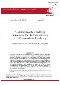
Figure 1: Head Mounted Devices render a warped view with tight control for each eye. Our approach for graph visualization uses techniques targeted specifically for such displays. Color in all figures corresponds to clusters.
While immersive techniques for scientific visualization have been a driving force behind the development of virtual reality systems, the application of immersive systems to information visualization has been comparatively sparse. Whether or not stereoscopy can be benefitial for many information visualization tasks is still an open question [5, 18]. However, graph visualizations in particular have been shown to benefit greatly [24, 25]. While there are several works that explore stereoscopic graph visualization, there are actually extremely few investigations into the applicability of VR to the field of graph visualization, and most of these simply use a standard graph approach and add stereoscopy [3]. The work we present here explores the possibilities of applying modern virtual reality hardware to create a more immersive graph visualization. Our graph visualization approach is designed specifically for a virtual reality environment and includes several novel techniques crafted expressly for this purpose. Specifically, the contributions of this work are: • 3 graph layout algorithms for the surface of a sphere • A spherical edge routing and bundling approach, to be viewed from the inside • An application of line rendering techniques from scientific visualizations to the field of graph visualization • A VR interaction paradigm for graph visualization 2 R ELATED W ORKS Stereoscopy and VR has a long history with scientific visualization, including GIS data [4], volume data [26], and medical imaging data [19]. When the data is inherently 3D and spatial, such techniques are a natural fit. Information visualization has made much less use of stereoscopic techniques. 3D in general has been used in information visualization for a long time [5]. It is often implemented poorly
or with negative effect, but for some tasks it has been shown to be beneficial, and stereoscopy compounds the benefit [18]. For graphs in particular, stereoscopy has been shown in multiple user studies to be very effective for graph visualization tasks [11, 24, 25]. While there are many graph visualization systems, the graph is still generally looked at from an external perspective. That is, approaches generally either take a 3D layout and add depth cues [24, 25], or take a standard 2D graph visualization and add a 3D stereoscopic extension such as using the 3rd dimension for highlighting [1]. In either of these cases, the display is often a monitor, and not an immersive system. Halpin et al. [14] use an immersive system, but they still used a standard 2D layout, and used the stereoscopy just for highlighting. And Barahimi and Wismath use a standard 3D layout for VR [3]. There are many graph layout algorithms. Many are forcedirected, while others compute the final result using linear algebra techniques on graph geodesics [13]. Still others use clustering techniques to define a layout [20, 21]. But immersion is generally a spherical paradigm, and few layouts work in a spherical space. [27] uses a self-organizing map to place a small graph on a sphere, but this is based on multidimensional node properties. Hyperbolic graph visualization works in a spherical space [22], but nodes/edges would go through the user’s location in the center of the sphere. Like most graph visualizations, one of the big challenges is how to effectively draw the large number of edges. Hierarchical edge bundling [15] is a common technique to route edges effectively. However, in 3D, conveying the depth of the edge adds an additional challenge. Streamline and Diffuse Tensor Imaging techniques have explored this problem for a long time. One basic technique is to add lighting to the lines [17]. This can be extended by improving the lighting model [2] at the expense of increased computational complexity. LineAO [7] employs ambient occlusion to emphasize both local and global line structures. Another common technique to show relative depth between lines is to employ halos [8, 9, 16]. Halos tend to become cluttered when there are too many densely packed lines, but we employ them as a highlighting technique. 3
A PPROACH
In a 2D environment (such as a monitor), it makes sense to arrange a scene in a 2D space. But in a virtual reality environment, the user’s location is the focal point of the scene, and there is freedom in the user’s view direction, as the entire sphere of directionality around that point is available. Visibility of the scene from the perspective of the user’s location is vital, so our approach takes advantage of this freedom by using graph layouts on the surface of a sphere, so that all nodes are equally visible to the user. In order to not occlude nodes, edges are routed outside the sphere along more distant control points in a bundled fashion. Lastly, as graph rendering involves rendering large numbers of lines, we employ dense line rendering techniques from scientific visualization works. 3.1
Spherical Graph Layout
Most existing layout algorithms work in a euclidean 2D space. While the surface of a sphere is also a 2D space, mapping a euclidean 2D space to the surface of a sphere is nontrivial, as na¨ıve projections introduce substantial distortions. As shown in Figure 2(a), regularly spaced points in a euclidean space would be skewed when projected to spherical space. In order to alleviate this, we compensate for these distortions before mapping to the sphere. Figure 2(b) shows that points that are equidistant on the hemisphere would be increasingly further apart in the euclidean space. As all of these rays can be considered as right triangles, it is easy to see that regular samples in θ on the hemisphere correspond to planar points at tan(θ ). So, before mapping to the hemisphere, we normalize the 2D graph layout and then distort it radially according to tan(d), where d is the distance in the plane from the contact point.
(a) Na¨ıve projection
(b) Radial projection
Figure 2: Mapping a 2D layout to a sphere. Na¨ıve azimuthal projection distorts distances (a). Warping the space according by d = tan(d) produces even radial spacing (b).
As our rendering approach utilizes a hierarchical edge bundling technique, the clustering hierarchy is also available to the layout algorithm. So while the mapping process could be applied to any 2D layout, we primarily focus on clustering based layouts such as the treemap and space-filling curve based approaches [21, 20]. One limitation of direct application of this projection is that it does not preserve angles or straight lines. This becomes especially apparent with rectangular input layouts (such as the treemap layout). For these layouts, the field-of-view (FOV) available is limited without inducing strong distortions in the shape of the sub-regions particularly in the corners which get wrapped much further around the sphere than the sides. One way to compromise on this is to warp the x and y dimensions independently. In this manner, straightness of lines are preserved as direct arcs on the hemisphere’s surface. However, distortions in area will increase as the FOV increases - notably, the area of regions near the corner of the layout would shrink to zero as they near the hemisphere boundary. In practice, this approach is best suited to a limit of 90◦ − 120◦ FOV, as shown in Figure 3(a). If the layout is more circular and less dependent on straight-line boundaries (as in the Gosper curve layout, or many force directed layouts), the angular preservation is less of an issue. As such, the direct azimuthal projection can be used to easily project the layout to the 180◦ hemisphere. An example of the gosper-based layout is as shown in Figure 3(b). For a completely immersive layout, the map should distribute nodes in all directions, not just on the front hemisphere. To do this, we employ a cubed sphere, utilizing a similar projection as described above. As before, the grid cells of each cube face are warped with a tangent function. But as in the rectangular projected method, it is imperative to preserve straight lines – particularly with respect to the borders, as the edges between the faces should be contiguous. Thus, the x and y dimensions are warped independently, forming an equiangular cubed sphere [6]. The space-filling curve layout then maps very nicely to this approach, as a space-filling curve can be defined on the surface of a cube as six planar space-filling curves, one one each face, that are still contiguous as one single curve [6]. To compute this layout, we break the graph into 6 sections, lay out the nodes for each section in a separate plane, warp their x and y values according to a tangent function, and finally project each plane onto the appropriate face of the cubed sphere. This ensures an even distribution of nodes over the entire surface, while preserving cluster locality. 3.2
Spherical Edge-bundling
Hierarchical edge bundling [15] is a commonly used technique for improving the legibility of dense or complicated graph visualizations. We apply a variant of this technique to our immersive graph visualization. Direct application of the technique to a spherical layout would not work well for our purposes, as the bundles would run through the inside of the sphere close to the viewer, obscuring the nodes of the graph. We alter the technique to better fit the spherical arrangement and improve visibility when viewed from the inside of the sphere by routing the edges around the outside of the sphere, with longer edges routed further away from the sphere than short ones, according to the clustering hierarchy.
(a) Equiangular Treemap
(b) Hemispherical Gosper
(c) Cubed Sphere Hilbert
Figure 3: Spherical graph layouts: 2D layouts can be mapped to the sphere with varying amounts of distortion. Preserving angles (a) is appropriate for rigid, rectangular structures, but is limited in field of view (FOV). Azimuthal mapping (b) works well for roughly circular layouts to use a full hemisphere. For full immersion (c), we use a space filling curve defined on a cubed sphere to cover the entire surface.
The first step is to route the edge around the outside of the sphere. That is, given the start point, end point, and a set of intermediate control points, all on the surface of the sphere, we want to compute a cubic B-spline that also lies on the surface. For the general case of de Boor’s algorithm, the B-spline is computed as:
j pi (t) =
( j j−1 j j−1 (1 − ri )pi−1 (t) + ri pi (t) if j > 0 pi if j = 0 t − ti j where ri = ti+k− j − ti
(1)
However, direct cartesian interpolation would fail to compute correctly on the surface of a sphere, as would interpolation in spherical coordinates. Instead, we modify de Boor’s algorithm to use a spherical linear interpolation (SLERP [23]), which is defined as: SLERP(p0 , p1 ,t) =
sin((1 − t)θ ) sin(tθ ) p0 + p1 , sinθ sinθ where θ = arccos(p0 · p1 )
(2)
Inserting this in de Boor’s algorithm yields a spherical B-spline: ( j−1 j−1 j SLERP(pi−1 (t), pi (t), ri ) if j > 0 j pi (t) = pi if j = 0 (3) t − ti j where ri = ti+k− j − ti In this manner, the spline is smooth from the perspective of the user in the center of the sphere. While more complicated splines are possible, this approach is relatively simple and computationally efficient enough to recompute upon interaction. An example of such a spline is shown as the yellow curve in Figure 4, which is computed according to the red control points. However, placing these curves on the surface of the sphere would render them all at the same depth, which not only causes edges to intersect, but also fails to take advantage of stereoscopy. So in addition to the angular spline computation, we also modulate the radius with a 1D spline by raising the control points off the surface of the sphere. Each control point corresponds with a node in the clustering tree, so we extend the radius of each control point according to
Figure 4: Hierarchical edge bundling routes edges with splines that follow the clustering hierarchy. For a sphere, we compute the spline in two stages. An angular spline (in yellow) is computed with spherical interpolation according to control points on the surface of the sphere (red points). Then the spline is extended radially by moving the control points outward (blue) and modulating the radius of the edge samples as a 1D spline (green).
the height of the corresponding clustering node (i.e. the distance to the furthest leaf/graph node). We then compute this spline using the de Boor approach (as shown above). In this manner, as the edge is routed up the clustering hierarchy, it moves further away from the user’s viewpoint, and it conversely approaches as it routes down the hierarchy. The result of this is that the larger, less precise bundles are also the furthest away, while shorter, more intricate structures remain close to the nodes. 3.3
Dense Edge Rendering
Rendering dense bundles of lines has been well studied visualization of scientific data, such as diffusion tensor imaging or streamline data. As such, there are numerous techniques available that could be applied to graph data, such as illuminated lines [2, 17], halos [8, 9], or LineAO [7]. While graph visualization should benefit from any of these techniques, there are some limitations to consider. For a HMD, high refresh rate and low latency are both of critical importance in order to avoid inducing nausea in the user. As such, we currently limit our approach to only the most efficient approaches possible. Also, for many HMDs, the number of pixels available are still relatively limited, and the HMD applies its own screen-space shader to handle distortion and chromatic correction, both of which dissuades the usage of screen-space techniques. As hardware continuously improves, the usage of more complicated techniques will become more appropriate, but for this work we limit
(a) Before selection
(b) After selection
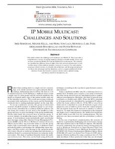
(a) 2D
(b) VR
Figure 5: When the user selects a node, it and all its neighbors were brought closer to the user, rendered with a halo effect, and labelled. Here, this is shown at an angle for illustrative purposes; in the HMD view, the nodes move straight towards the user.
Figure 6: In a 2D view, the whole graph may be visible, but there is no discernable shape to the edges, making them difficult to follow. In a VR environment, only a small section of the graph is visible at a given time, but structure is more tangible.
ourselves to illuminated line techniques, with the exception that we use halo techniques for interactive highlighting.
feel equivalent to an all encompassing display. While further user evaluations are needed to prove its effectiveness, we found the preliminary results to be compelling.
3.4
Interaction
Interfaces within HMD environments is an area of many open challenges, and also opportunities, Since the user loses all sight of their hands from within the device, traditional mouse and keyboard interaction is limited. While we do not address specific interaction challenges here, we did want to avail ourselves of the head tracking capabilities of the HMD. Since the device tracks the position and direction of the camera, we can also utilize this information to determine what the user is looking at, use this information to identify focal points, aid the user in making selections, and provide instantaneous details of the selected data. To facilitate this, we use a targeting reticule that is aimed primarily by the user’s head motion, but also augmented by the mouse if desired. That is, as the user moves their head, the targeting reticle stays fixed with respect to their view, but it can be adjusted within the view area using the mouse. In order to alleviate the need for precise head motion, any node within the reticle can be considered for selection, and the closest to the center is selected. When the user uses this reticle to select a node, the node and all its neighbors are brought closer to the user’s viewpoint. Similarly, all the control points for all affected edges are also brought closer. This serves to separate the selected node and its neighbors from the rest of the graph and bring them into a closer, focal plane. To further accentuate this, we apply a halo technique to the selected node’s edges. The overall effect is that the selection is easily distinguished from the remainder of the graph, and the immediate connections are easy to visually follow to their destinations. Multiple nodes can be selected and brought into this focal plane, allowing the user to explore any potentially interesting paths or relations that they find. 4
D ISCUSSION
We have implemented and tested our system against a number of interesting data sets, including egocentric social networks, website hyperlink networks, a programing language codesigner network, and networks of sports players who have played on the same team and of teams that have traded players [12]. While not easily apparent in the figures in the paper, the stereoscopic views were quite effective for visualizing complex networks. In 2D representations, the whole network may be summarized in one static view, but it can be difficult to follow an edge through the bundles. In our approach, the shapes of the edges are much clearer. And while only a small range of the graph is visible at a time, spatial memory is persistant, making the immersive network
5
F UTURE W ORK
While we have limited ourselves to simple lighting techniques to augment the stereoscopy in conveying depth information, more advanced techniques such as LineAO [7] should be possible, we plan further investigation into the applicability of these approaches. There are many other layouts that could work well in an immersive environment, which we intend to explore. Many traditional layouts can be computed in 3 dimensional space and augmented with fisheye or other distortion techniques. And there are some graph visualizations that are designed for a spherical space already that could map very well to an immersive environment, such as hyperbolic graph layouts [22]. We have implemented a basic selection interaction method, but there is a vast range of possible interaction methods that are yet to be explored. Having a dedicated region of space within which the user can introduce selected foci and directly investigate their interaction is one such possibility. Gestural interaction capabilities are another direction of investigation, as visibility within HMDs limits usage of traditional input devices. Finally, concrete evaluation of immersive approaches necessitate extensive user studies to prove their effectiveness. 6
C ONCLUSION
We have presented a new approach to visualization of graph data through the use of an immersive virtual reality environment. While stereoscopy has previously been shown effective for graph visualization, ours is the first approach that is designed specifically for immersive virtual reality. And while we have designed our approach around the use of a head mounted display, it should also be effective in other immersive virtual reality environments. As head mounted displays and other stereoscopic devices become more prevalent, approaches such as ours will continue to become more important. While we have demonstrated our approach’s efficacy, it is an early foray into exploring virtual reality techniques for graph visualization, and more techniques are yet to be discovered. ACKNOWLEDGEMENTS This research is sponsored in part by the National Research Foundation of Korea via the BK21 PLUS program, by the U.S. National Science Foundation via grants NSF DRL-1323214 and NSF IIS1320229, and by the UC Davis RISE program.
R EFERENCES [1] B. Alper, T. Hollerer, J. Kuchera-Morin, and A. Forbes. Stereoscopic highlighting: 2d graph visualization on stereo displays. IEEE Transactions on Visualization and Computer Graphics, 17(12):2325–2333, 2011. [2] D. C. Banks and C.-F. Westin. Global illumination of white matter fibers from dt-mri data. In L. Linsen, H. Hagen, and B. Hamann, editors, Visualization in Medicine and Life Sciences, Mathematics and Visualization, pages 173–184. Springer Berlin Heidelberg, 2008. [3] F. Barahimi and S. Wismath. 3d graph visualization with the oculus rift. In Poster at Graph Drawing, 2014. [4] R. Bennett, D. J. Zielinski, and R. Kopper. Comparison of interactive environments for the archaeological exploration of 3d landscape data. In Proceedings of IEEE VIS International Workshop on 3DVis, nov 2014. [5] R. Brath. 3d infovis is here to stay: Deal with it. In Proceedings of IEEE VIS International Workshop on 3DVis, nov 2014. [6] J. M. Dennis. Partitioning with space-filling curves on the cubedsphere. In IPDPS, page 269. IEEE Computer Society, 2003. [7] S. Eichelbaum, M. Hlawitschka, and G. Scheuermann. LineAO - Improved Three-Dimensional Line Rendering. IEEE Transactions on Visualization and Computer Graphics, 19(3):433–445, Mar. 2013. [8] M. H. Everts, H. Bekker, J. B. T. M. Roerdink, and T. Isenberg. DepthDependent Halos: Illustrative Rendering of Dense Line Data. IEEE Transactions on Visualization and Computer Graphics, 15(6):1299– 1306, Nov. 2009. [9] M. H. Everts, H. Bekker, J. B. T. M. Roerdink, and T. Isenberg. Flow visualization using illustrative line styles. In Proceedings of ICT.Open, ASCI – IPA – SIKS tracks, November 14–15, Veldhoven, The Netherlands), 2011. [10] A. Febretti, A. Nishimoto, T. Thigpen, J. Talandis, L. Long, J. D. Pirtle, T. Peterka, A. Verlo, M. Brown, D. Plepys, D. Sandin, L. Renambot, A. Johnson, and J. Leigh. Cave2: a hybrid reality environment for immersive simulation and information analysis. Proc. SPIE 8649, The Engineering Reality of Virtual Reality 2013, 8649, 2013. [11] N. Greffard, F. Picarougne, and P. Kuntz. Beyond the classical monoscopic 3d in graph analytics: an experimental study of the impact of stereoscopy. In Proceedings of IEEE VIS International Workshop on 3DVis, nov 2014. [12] Griffen, Brendan. Graphs Of Wikipedia: Sports. http:// brendangriffen.com/blog/gow-sports/. [13] S. Hachul and M. J¨unger. An experimental comparison of fast algorithms for drawing general large graphs. In Proceedings of the 13th International Conference on Graph Drawing, GD’05, pages 235–250, Berlin, Heidelberg, 2006. Springer-Verlag. [14] H. Halpin, D. J. Zielinski, R. Brady, and G. Kelly. Exploring semantic social networks using virtual reality. In A. Sheth, S. Staab, M. Dean, M. Paolucci, D. Maynard, T. Finin, and K. Thirunarayan, editors, The Semantic Web - ISWC 2008, volume 5318 of Lecture Notes in Computer Science, pages 599–614. Springer Berlin Heidelberg, 2008. [15] D. Holten. Hierarchical edge bundles: Visualization of adjacency relations in hierarchical data. IEEE Transactions on Visualization and Computer Graphics, 12(5):741–748, Sept. 2006. [16] M. Luboschik and H. Schumann. Illustrative halos in information visualization. In Proceedings of the Working Conference on Advanced Visual Interfaces, AVI ’08, pages 384–387, New York, NY, USA, 2008. ACM. [17] O. Mallo, R. Peikert, C. Sigg, and F. Sadlo. Illuminated lines revisited. In Visualization, 2005. VIS 05. IEEE, pages 19–26, Oct. 2005. [18] J. P. McIntire and K. K. Liggett. The (possible) utility of stereoscopic 3d displays for information visualization: The good, the bad, and the ugly. In Proceedings of IEEE VIS International Workshop on 3DVis, nov 2014. [19] K. Mirhosseini, Q. Sun, K. C. Gurijala, B. Laha, and A. E. Kaufman. Benefits of 3d immersion for virtual colonoscopy. In Proceedings of IEEE VIS International Workshop on 3DVis, nov 2014. [20] C. W. Muelder and K.-L. Ma. Rapid graph layout using space filling curves. In In Proceedings of IEEE Conference on Information Visualization (InfoVis), pages 1301–1308, 2008.
[21] C. W. Muelder and K.-L. Ma. A treemap based method for rapid layout of large graphs. In In Proceedings of IEEE Pacific Visualization Symposium, Mar 2008. [22] T. Munzner. H3: Laying out large directed graphs in 3d hyperbolic space. In Proceedings of the 1997 IEEE Symposium on Information Visualization (InfoVis ’97), INFOVIS ’97, pages 2–, Washington, DC, USA, 1997. IEEE Computer Society. [23] K. Shoemake. Animating rotation with quaternion curves. SIGGRAPH Comput. Graph., 19(3):245–254, July 1985. [24] C. Ware and P. Mitchell. Reevaluating stereo and motion cues for visualizing graphs in three dimensions. In Proceedings of the 2Nd Symposium on Applied Perception in Graphics and Visualization, APGV ’05, pages 51–58, New York, NY, USA, 2005. ACM. [25] C. Ware and P. Mitchell. Visualizing graphs in three dimensions. ACM Trans. Appl. Percept., 5(1):2:1–2:15, Jan. 2008. [26] C. H. B. Weyers, B. Hentschel, and T. W. Kuhlen. Interactive volume rendering for immersive virtual environments. In Proceedings of IEEE VIS International Workshop on 3DVis, nov 2014. [27] Y. Wu and M. Takatsuka. Visualizing multivariate network on the surface of a sphere. In Proceedings of the 2006 Asia-Pacific Symposium on Information Visualisation - Volume 60, APVis ’06, pages 77–83, Darlinghurst, Australia, Australia, 2006. Australian Computer Society, Inc.