Spherical Planetary Robot for Rugged Terrain Traversal Laksh Raura Space and Terrestrial Robotic Exploration (SpaceTREx) Lab Arizona State University 781 S Terrace Mall, Tempe, AZ 85287
[email protected]
Andrew Warren Space and Terrestrial Robotic Exploration (SpaceTREx) Lab Arizona State University 781 S Terrace Mall, Tempe, AZ 85287
[email protected]
Jekan Thangavelautham Space and Terrestrial Robotic Exploration (SpaceTREx) Lab Arizona State University 781 S Terrace Mall, Tempe, AZ 85287
[email protected]
In this work, we develop a prototype 2 kg holonomic robot that is spherical and contains a pair of grooved wheels that can traverse over rugged environments (Figure 1). In addition, the robot can also roll unpowered down slopes. The robot has an actuator that enables it to hop 8-50 cm under Martian gravity. The system is powered using a primary or rechargeable battery. With a rechargeable, the total energy in the batteries is 2.3 Wh, while for nonrechargeable 7 Wh can be achieved. The robot communicates wirelessly using radio achieving data rates of up to several Mbps with a nearby ground rover located up to a few kilometers away. Navigation is performed using onboard wheel encoders and a pair of stereo cameras. This is sufficient to perform standard Simultaneous Localization and Mapping (SLAM). Our current prototype utilizes a Raspberry PI, but the platform can use space-qualified radiation hardened computers designed for Mars.
Abstract—Wheeled planetary rovers such as the Mars Exploration Rovers (MERs) and Mars Science Laboratory (MSL) have provided unprecedented, detailed images of the Mars surface. However, these rovers are large and are of highcost as they need to carry sophisticated instruments and science laboratories. We propose the development of low-cost planetary rovers that are the size and shape of cantaloupes and that can be deployed from a larger rover. The rover named SphereX is 2 kg in mass, is spherical, holonomic and contains a hopping mechanism to jump over rugged terrain. A small lowcost rover complements a larger rover, particularly to traverse rugged terrain or roll down a canyon, cliff or crater to obtain images and science data. While it may be a one-way journey for these small robots, they could be used tactically to obtain high-reward science data. The robot is equipped with a pair of stereo cameras to perform visual navigation and has room for a science payload. In this paper, we analyze the design and development of a laboratory prototype. The results show a promising pathway towards development of a field system.
Spherical robots are not new [1-3], however our design combines a hopping mechanism with a holonomic chassis. Thanks to 3D prototyping, we have designed and tested custom grooved wheels to handle rugged terrain. These small, low-cost robots would complement a larger, more capable platform such as the MSL.
TABLE OF CONTENTS 1. INTRODUCTION ...……………………….……….. 1 2. BACKGROUND ......................................................... 2 3. MISSION REQUIREMENTS ...................................... 2 4. ROBOT DESIGN ....................................................... 2 5. EXPERIMENTS ......................................................... 6 6. RESULTS AND DISCUSSION ..................................... 7 7. CONCLUSIONS ......................................................... 8 REFERENCES............................................................... 9
1. INTRODUCTION Wheeled planetary rovers such as the Mars Exploration Rovers (MERs) and Mars Science Laboratory (MSL) have provided unprecedented, detailed images of the Mars surface. These rovers have helped to discover sedimentary rock, evidence for past water flow and image rare phenomena unique to Mars, such as the dust devils and "blueberry" mineral chondrites. These rovers provide detailed in-situ images and scientific data. However, these planetary rovers are large, with a mass of 180 kg to 900 kg and are of high-cost. This is required to house sophisticated science instruments and in-situ laboratories. Rapid advancement in miniaturized electronics, power supplies, actuators and even structural materials such as high-strength metallic glass make it possible to develop small, low-cost robots for planetary surface exploration.
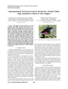
Figure 1: Spherical, cantaloupe sized robots (inset) can be deployed from large rovers such as the Mars Science Laboratory and access rugged terrains too risky to traverse by large rovers or be visible to orbital assets such as Mars Reconnaissance Orbiter. One or more of these robots may be deployed from an MSLsized rover to explore rugged environments that are inaccessible or too dangerous for a flagship rover. These small robots may be deployed on one-way journeys down 1
slopes, crater rims, canyons and cliffs. Multiple network of robots maybe able to autonomously plan, navigate and explore extreme environments [5, 14, 17-18].
Typically, these mechanisms presented provide very limited control on the direction of the hop. Burdick and Fiorini proposed design for a minimalist jumping robot [8] for planetary exploration. This robot could jump 80 cm and has the ability to control direction of hop. It could leap 40-60 cm based on the angle of projectile. Some other robots like Sandflea [9] by Sandia National Laboratory uses hydraulics for hopping and could hop 50 times its length. But such methods are not viable for application in space or planetary environments. Additionally, the robot could perform maximum 25 hops on a single charge.
We have developed a laboratory prototype and accompanying low-gravity simulation facility to evaluate the mobility performance of the rover under various Mars and Lunar surface conditions. With these results, we hope to further iterate on the robot design towards a platform ready for extensive testing in the Grand Canyons, Meteor Crater and Flagstaff region of Arizona. In this paper, we first review past work on small spherical robots for exploration in Section 2, followed by presentation of mission requirements for typical robots of this size in Section 3. In Section 4, we present the robot design followed by brief presentation of the experiment setup in Section 5. This is followed by results and discussion in Section 6 and conclusions in Section 7.
3. MISSION REQUIREMENTS The primary goal of this research effort is to develop lowcost, low-mass spherical robots for planetary exploration. The robot would perform the following exploration tasks:
2. BACKGROUND Multiple spherical shaped robots have been proposed for terrestrial and planetary exploration. The RoBall [1] proposed by group from Universite De Sherbrooke is a spherical robot which moves by shifting a suspended mass at its center. This limits the sensors that can be used with the system. Another terrestrial spherical robot, Kickbot [2] was proposed by students at MIT. It uses two external hemispherical shells as wheel for mobility. The concept was designed as a toy. The design has very high maneuverability. Multiple concepts for inflatable spherical robots have been proposed by research teams from Uppsala University, North Carolina State University (NCSU) [3] and University of Toronto. The research team from Uppsala University proposed a design called Spherical Mobile Investigator for Planetary Surface (SMIPS) [4]. These rovers have the advantage of travelling over large distances and steep inclination. However, their reach is limited to benign sandy terrain to avoid damage from sharp rocks.
1.
Geology by stereo imaging: Identifying size and size distribution of rocks.
2.
Wide area investigation: Access wide areas, multiple locations and viewpoints at once using multiple robots to record surface phenomena.
The exploration requirements for the robots are as follow: 1. Ability to traverse over flat, sandy and rocky terrains 2. Access features like pits, craters and cliffs 3. Assist/complement exploration with larger rovers To accomplish these tasks, the robot require a robust mobility system to travel short distances. To facilitate exploration over a large area, multiple robots may be used. Therefore, each robot would be equipped with a wireless communication system to coordinate exploration and transfer collected data to local server that may be an onorbit satellite or nearby large rover.
4. ROBOT DESIGN
Other mobility methods were also considered for robot development and it was identified that hopping provides advantage for travelling over longer distances in comparison to rolling alone. This also enable smaller robots to overcome obstacles at least twice the size of the robot. Previous concepts include a series of micro hopping robots developed at MIT [5, 10, 13-14]. These micro-hopping robots would use ‘artificial muscle’ actuators that are used to energize a spring based hopping mechanism. The robots would be powered using fuel-cells [10, 13, 19] that provides high specific energy. Apart from extreme environment exploration, potential applications for this technology also include terrestrial sensor networks. ‘Grillo’ is another hopping robot developed at Sant’Anna University [6] and the 7 gram, grass-hopping robot developed at EPFL [7] shows that compact hopping mechanisms can be developed. As an alternative to mechanisms, rocket-powered hopping has also been proposed for planetary exploration [14].
Taking into consideration all the above requirements, our robot design is shown in Figure 2. The inner shell diameter is 15 cm. The inner body is divided into 3 horizontal sections with middle section 4.5 cm thick.
Figure 2: SphereX Robot showing the wheels, stereo cameras and hopping mechanism.
2
The shell thickness was chosen to be 0.3 cm for mechanical strength. The top and bottom section have one camera each, spaced 65 mm apart for stereo imaging. The top section contains the robot control system (Figure 3). The middle section (Figure 4) houses the primary mobility system and the bottom (Figure 5) contains the hopping mechanism.
The weight was concentrated in the bottom section which displaced the center of gravity of the robot and ensured mobility by relative motion between wheels and the core section. Figure 6 shows a CAD model of inner shell and exclude the two wheels. Hopping was chosen as the secondary mobility method as it helps to overcome larger obstacles and facilitates faster travel compared to rolling. The two external hemispherical shells (the wheels) were designed with grousers to assist mobility over rocky as well as sandy terrain. These grousers also increase the available traction in low-gravity environments. The wheels are 20 cm in diameter.
Figure 3: SphereX Robot top section contains a camera and the control system electronics.
Figure 6: SphereX body showing the motor shafts, hopping mechanism and stereo camera. External Shell and Drive Train Design The drive train was designed for rolling mobility. Table 1 shows the critical parameters for the drive-train design. Table 1 - Parameters for Drive Train Design Figure 4: SphereX Robot middle section contains the motors, communication board and power electronics, with room for a science payload.
Parameter g Μ μrr Mr θs Vmax ta Rw Wn Rf Nw
Gravity Constant Friction Coefficient (sand) Rolling Friction (Sand) Mass of robot Max grade to be climbed Maximum linear velocity Time to acceleration Wheel radius Normal force per wheel Resistance Factor (grousers) No. of wheels
Value 1.6 m/s2 0.6 0.15 2.0 kg 14 o 0.03 m/s 1s 9.9 cm 1.6 N 20 % 2
The motor selection was done on the basis of total traction force required for traversing over a given terrain. The total tractive force is given by Equation 1:
Figure 5: SphereX Robot bottom section contains the hopping mechanism, batteries and a camera. 3
FTT = Ffr + Fs + Fa
The robot wheels were designed to be 20 cm in diameter with the grousers. Grousers help increase the traction on soft soil and help overcome small obstacles. The number of grousers depends on the grouser height and wheel sinkage depth. It is given by the relation defined by Equation (7) [16]:
(1)
Where FTT is the total tractive force, Ffr is the frictional force, Fs is the force required to climb the slope and Fa is the force required to accelerate. Ffr, Fs and Fa are given by Equation (2), (3) and (4) respectively:
Ffr = Mr ∗ μrr
(2)
Fs = Mr ∗ sin θs
(3)
Fa = Mr ∗ Vmax ⁄g ∗ Ta
(4)
φ