spring-fork is attached to an object and defines a contact point for transfer .... is concentrated to its center of mass and therefore the moment of inertia around.
Spring-Based Manipulation Tools for Virtual Environments Michal Koutek and Frits H. Post Delft University of Technology, Delft, The Netherlands email: {m.koutek, f.h.post}@cs.tudelft.nl Abstract. In this paper we present new tools for user interaction with virtual worlds, to bring more natural behavior into the manipulation of objects in virtual environments. We present some principles of physically realistic behavior of virtual objects and a set of user input techniques suitable for semi-immersive VR devices such as the Responsive Workbench. We introduce springs, spring-forks and spring-probes as new tools for assisting direct manipulation of objects in VEs. In this paper we focus on controlling rotational motions.
1
Introduction
In user interaction with virtual worlds, consistent and realistic behavior of objects is very important. We want objects to respond in a natural and predictable way to our actions. But usually VE objects are weightless and unsubstantial, and they move without friction of inertia; this leads to altogether ’unphysical’ behavior and unpredictable responses, especially in semi-immersive environments such as the Responsive Workbench (RWB), where real and virtual worlds co-exist, and should follow the same natural laws. We present a graphical force-feedback method and we provide a visual interface as an emulation of direct force input.
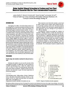
Fig. 1. Illustration of spring-based tools
We do this by the use of spring-based tools attached to objects assisting the manipulation, based on the following assumptions: – a linear relation of force with spring compression / extension is intuitively understood and shown by the spiraling shape of a spring. Thus, even without exerting real force, a user has an intuitive notion of transforming a change of spring length to a force.
– bending and torsion of a shaft is used to show forces and torques exerted on virtual objects – the relation between object mass and size is also intuitive, but application dependent. Specific mass of objects should be user specified. A massless world can always be created by setting all masses to zero. – the RWB provides a natural ground plane for objects at rest. – stability is introduced by friction and damping, reducing excessive effects of input actions on objects, and reducing undesired oscillations. – physical contact of objects is intuitively equivalent with geometric intersection, and sound can be used to provide contact feedback. We introduce a set of spring-based tools for providing the basic manipulation tasks (see Figure 1). We hypothesize that dynamics will provide intuitively consistent and predictable behavior of the objects in the virtual world, and that interactive manipulation will therefore be easier and more natural. – spring is attached to the center of an object. It assists linear motions. The tool has 1 DOF (degree of freedom), the length of the spring, and controls 3 DOF (xyz) of an object. – spring-fork is attached to an object and defines a contact point for transfer of forces and moments to the object. It assists translations and rotations. The tool has 3 DOF (extension, bend, torsion) and controls 6 DOF (xyz+hpr) of an object. – spring-probe can be used for probing the material stiffness of an object or pushing an object. The tool has 1 DOF (length) and can control 3 DOF (xyz) or 1 DOF (pressure) of an object. Why spring-based tools? In VR it is just as easy to select and manipulate large and heavy objects as small ones. This may sometimes be an advantage, but it is not according to our expectations. Therefore, we will try to give the user a feeling of weight or mass of objects. We propose the use of spring-tools as a link between user’s hand and a manipulated object. By this, we can obtain a natural visual feedback during manipulation. When the user lifts a heavy object, the spring will extend proportionally to the object’s weight. Also, acceleration and deceleration of the motion will affect the visible length of the spring. The fork metaphor seems to be very intuitive. For object selection the fork has to be inserted in an object. The user can fix the position and the orientation of the fork inside the object. Then the spring part of the fork gives a visual dynamic feedback during the manipulation of the object. It is also intuitive that rotating the fork should also rotate the object. The user controls one end of the fork and the other end is influenced by the object. The fork can bend, extend (compress) or twist according to the laws of mechanics. We will demonstrate the usage of the spring-tools with a simple object assembly task, which is easy in a real world but hard to simulate in a virtual environment; see Figure 15.
In this paper, we first review some related work and provide an overview of dynamic interaction techniques in VR. We concentrate on the use of dynamics in user interaction, especially the use of springs. New in this paper is the idea of controlling all 6 DOF of an object with a single spring-tool (the spring-fork). Crucial is control of the rotational motions. Also innovative is the spring-probe tool. With the current implementation of a micro-world we demonstrate the suggested dynamic interaction in VEs. Finally, we present areas for future work.
2
Related Work
We have studied interaction techniques used in fully immersive (CAVE, HMD) and semi-immersive virtual environments (RWB). Surveys of interaction techniques for VR systems can be found in [4, 5]. The problems of mechanics and dynamics have been studied extensively from many different points of view. It is outside the scope of this paper to review this whole field. We do not have the intention to implement a fully realistic dynamic manipulation system, but rather a limited and simplified set of basic physics to assist the manipulation of objects in VE. In the VR literature, not much work has been published on incorporating dynamics in user interaction. Usually, haptics is used for this purpose, [3, 6]. In [1, 2], springs are introduced as a tool for direct manipulation of objects in VEs. In [1], springs are used to control the translational motions and they give a visual force feedback of applied forces. In [2], springs are also used to give a visual force feedback. They demonstrate a set of multi-spring configurations to control objects. Their force-based interaction approach allows multiple hands and users to manipulate the same object. Authors [1, 2], emphasize the problem of simulating the dynamics and collision behavior with real time frame rates. In this paper, we will present an approach of having a set of very simple manipulation tools which reflect dynamic object behavior during the manipulation. Currently, we put our interest in single-handed manipulations. We will extend the spring metaphor [1] to improve the user’s feeling of mechanics and dynamics in virtual environments, and we will concentrate on controlling the rotation and the translation with the spring-fork tool.
3
Dynamics on the Workbench
As discussed before, we introduce the concepts of force, inertia, gravity, contact and surface friction to provide a virtual world in which objects behave more naturally. Objects behave according to physical laws and also the interaction is physics-based. We are exploring the relevant laws of mechanics. For object collisions, there are principles of conservation of momentum and of energy, and reversible conversion between kinetic and potential energy. 3.1 Method Description A specific mass is assigned to each object. From the volume of an object its mass is calculated. To make objects move, forces are needed. In our case, the gravity force and the force exerted by the user are acting. Counter-acting forces
are the friction force with the surface and the air resistance force. For stability a damping force is implemented. We use a simplified implementation of the physics laws in our virtual world. We will ignore air-resistance. We will only use the static friction µ, when user drags an object across a surface. At small speeds µ is constant. When the forces act on the object at the certain distance from the center of its mass it induces a moment and a torsion. The final rotational motion depends also on the moment of inertia of the object which corresponds to the axis of rotation. For simplicity, we will consider now that the whole mass of the object is concentrated to its center of mass and therefore the moment of inertia around 2 m, where rO is the perpendicular distance of the center axis O will be IO = rO of mass from the axis O. To make the simulation more realistic, it is possible to include a precise calculation of the moment of inertia for a given object and a certain axis of rotation. Here is the overview of the laws of mechanics discussed above: 2
Force law: fa = ma = m dv = m ddt2x dt Gravity law: fg = mg Friction force: fr = µN = µ.mg
Spring force: Damping force:
Linear Momentum:
Angular Momentum:
F = ma = mv˙ =
n �
Fi
i=1
fs = −kx fd = −c. dx dt
M = I� = I ω˙ =
n �
(ri × Fi )
i=1
Where: m=mass, f =force, x=position, v=velocity, a=acceleration, g= gravity acceleration, µ= static friction coefficient, k= spring constant and c= damping factor, ω=angular velocity, �=angular acceleration, ri =force position, I=moment of inertia.
During manipulation, a spring-tool is attached to an object. Each spring-tool (spring, spring-fork, spring-probe) has to be calibrated with the manipulated object. That’s done automatically from the weight and the dimensions of the object. The calibration procedure consists of calculating of spring and damping constants and choosing a suitable size of the spring-tool. For heavy and large objects a stronger and larger spring-tool is used, and a weaker and smaller springtool for light objects. More about the basic spring-tool, the common spring, which is only used for linear motions, can be found in [1]. We will now concentrate on the spring-fork tool. 3.2
Spring-Fork
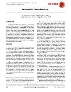
Fig. 2 Spring-damper systems for each deformation parameter of the spring-fork
We introduce here a 3 DOF spring-tool, the spring-fork. Each spring-damper in each DOF is calibrated to hold the attached object with a certain extension. In case of the spring-fork there are three spring-dampers, one for each DOF: bend, stretch, torsion.
3.3
Spring Damper
The basic component of spring-tools is the spring-damper. To reduce oscillations during manipulation, when an object is attached to a spring-tool, we have implemented a spring mass-damper system for each DOF. m¨ x(t) + cx(t) ˙ + kx(t) = f (t) Here m is the mass of the object, x(t) is the extension/compression of the spring, f (t) is the force acting on the object only in x(t) direction, k is the spring constant and c is the damping factor.
Fig. 3
Spring Damper System
Fig. 4
Damping Comparison
If xs is the static extension of the spring and xd is the change of extension during the motion, we can simplify the spring-damper formula by assuming: x = xs + xd and kxs = mg. Then we get the following differential system: mx¨d + cx˙d + kxd = 0;
x(0) = x0 ,
˙ x(0) = v0
To avoid unwanted oscillations of the spring-damper we use a critical damping solution: xd (t) = (A.t + B)e−αt ; with A = v0 + x0 α; B = x0 α=
c 2m ;
ω0 =
� k/m
√ For critical damping is: α = ω0 thus c = 2 mk. From Figure 4 is clear that the critical damping quickly converges to the zero but in fact it takes an ”infinite” time to reach the zero. Thus when the simulation reaches a threshold, it stops. There is also another problem. Initial conditions are changing as the user moves his/her hand. Therefore, we have to re-initialize x0 and v0 each simulation time step.
4
Spring-fork Model
To implement the spring-fork manipulation, we first need to create a model of the spring-fork which would be scalable and deformable with bend, stretch and torsion deformations. The fork consists of a rigid part (the fork end) and a flexible part (the spring part), see Figure 5.
Fig. 5 Spring-fork model; Space conversions of the fork’s vertexes and normals
Fig. 6 Reconstruction of the XYZ coordinates of the deformed fork
The 3D model of the fork is converted to normalized cylindrical coordinate space, which is used to perform the fork deformation. All vertices and normal vectors are converted once and stored in memory as the initial and the normalized form of the fork. For a given scale of the spring-fork (Spr diam, Spr height) and a given deformation (bend, stretch, torsion) we have to reconstruct the final XY Z coordinates (Figure 6). The torsion parameter of the spring-fork is the difference between twist0 and twist1 . The bend and the stretch parameters are built in the parametric function f (t). From Figure 6, it is clear how the LCS (local coordinate system) rotates along the function f (t). So for each position at f (t) we need to know the tangent vector, thus f � (t) which corresponds to the Z-direction of the LCS. The fork-ending is attached at the end of the spring and it is aligned with the last LCS.
Fig. 7
Deformation of the spring-part
Fig. 8
S-shape deformation (due object collision)
Figure 7 shows deformations of the spring-part of the fork. The first example is without torsion and the second shows the both bending and torsion. The deformation function f (t) needs explanation. The problem of object or beam bending is not trivial. Bending depends on the profile along the length the object, on the material structure, on the type of load and on other parameters. In general it is a complex problem. A full general solution of the mechanical problem would be too time consuming, so we will use a simplified solution that will satisfy our needs. We will assume that the load on the fork is concentrated. We designed an arclength parameterized B´ezier function for bending and S-shape deformation. We had to incorporate a compensation for changes in length of the arc, to keep its length constant without stretching. When the object was bent without changing
length, we built the stretching ability in the deformation function. Torsion is also rather complex to perform in real time, so we also made a very significant simplification for this. It is obvious that the deformation function needs to be calibrated to a certain range of forces, resp. to the virtual world and all the objects and their weights and forces which they could produce. We have calibrated the spring-fork tool in our mini-world for the range of object weights (0.0 vkg, 300.0 vkg), vkg = virtual kilograms. We must mention the problem of different measurement units in a virtual world and a real world where the user is standing. The real acceleration differs from the virtual acceleration, and certainly the real force applied by the user has different scaling than the virtual one of the object. The calibration procedure takes care of this problem. Spring-fork Parameters There are two major inputs to the spring-fork tool. Using the tracked stylus, the user controls the initial position of the tool: the fork axis and twist0 . The attached object applies a force and a moment to the fork-end and causes a deformation of the spring part of the tool. See Figures 9 and 10.
Fig. 9 Initial state Fig. 10 Bent, stretched and of the spring-fork twisted spring-fork The force applied on the object Fobj is decomposed into the stretching force (parallel with the fork axis) and the bending force (perpendicular to the fork axis). Absolute values are calculated by using angle P hi. We designed the spring-fork tool in such a way that it is possible to choose which of the 3 deformation DOF will be active: bending, stretching, torsion, or any combination of these. Of course, the user can change the stiffness of each DOF, for example to set up a stretch and a torsion resisting spring-fork which will easily bend only. In Figure 8, there is a torsion-free spring-fork (load: 100 vkg) showing an S-shaped bending during object collision.
5
Spring-fork Manipulation
The object selection is done by inserting the spring-fork into object. When the fork is inside the object is highlighted. The user can then still adjust the position of the fork inside the object. To begin the manipulation a button must be pressed. Manipulation stops when the button is released.
The manipulation procedure can be decomposed into several stages (Figure 12). The initial stage is the moment of selection. The position and orientation of the inserted fork will be kept for the whole manipulation. Only the spring-part of the tool will change.
Fig. 11
Object selection
Fig. 12
Manipulation procedure
The next stage is the new position and the rotation of the user’s hand and re-initialization of the spring-fork. The bend and the stretch deformations are performed first. After this torsion is calculated. This configuration (position and orientation of the object together with the deformed spring-fork) becomes a candidate for the new step, but first possible collisions with other objects have to be detected. If there is no collision, the candidate configuration will be used to re-initialize all three spring-damper systems, and they transform the current configuration to the new configuration. The spring-dampers of the spring-fork produce each new time step a new configuration of the object and the fork, but the user has meanwhile repositioned his hand. This triggers the next reinitialization of the system. All the above steps make this simulation rather complex, especially the handling of the collisions of objects. Currently, we use a simple method for collision checking. First, we check bounding volumes collisions, then we evaluate collisions of triangles. To find the position and the orientation for the contact of two objects we use a binary subdivision collision algorithm which finds an approximate solution in 8 subdivisions.
6
Manipulation Experiments
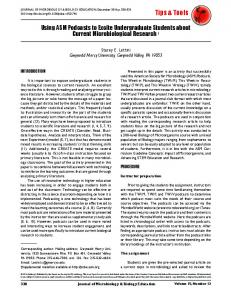
To test the concepts of this paper, we have implemented an experimental application where the user can perform dynamic spring manipulation with virtual objects in a mini-world. The mini-world consists of several boxes and spheres which has to be assembled into the blue box (Figure 15). This task can be done either with spring-based tools or with common direct manipulation tools. The basic concept of the RWB is that the user is standing in the real world, where the physical laws apply, and is partly immersed in the virtual mini-world which is projected on the Responsive Workbench. The user can compare the advantages of the spring-tools to the common tools (direct or ray casting manipulation). Finally, the user can also observe a visual feedback of dynamic behaviour of manipulated objects. Actual results and animations can be found at our web-site [7].
6.1 Notes on Implementation We use the VR Responsive Workbench, based on an SGI Onyx 2, with 4x MIPS R10000, 1xIR2 graphics pipe, a stereo projection table and the Fastrak tracking system for measuring the position and the orientation of user’s head and hand (stylus pointer). For implementation we have used C++ and our RWB library based on Iris Performer and OpenGL. We have implemented our scheme for collision checking, a simplified dynamic object behavior and the spring-based manipulation tools. 6.2 Spring-fork Manipulation Examples The images in this section were created using our RWB Simulator library [7]. An object is selected by inserting the spring-fork into it (Figure 11). When the user has adjusted the fork inside the object, the manipulation can start. As mentioned before, a user can switch the deformation DOFs of the springfork on and off. For example, a manipulation with a torsion-resistant spring-fork is shown in Figure 13.
Fig. 13
Torsion resistant spring-fork
Fig. 14
Spring-fork in torsion
When the all deformation DOFs of the fork are set on the spring-fork manipulation with the box would look like in Figure 14. Torsion in the spring-fork and the rotation of the object are caused by the moment which is applied at the fork-ending. The user can compensate the rotation of the object by turning the spring-fork around its axis in the opposite direction. The spring-damper of the torsion parameter will take care of the transformation of the rotation to the attached object.
Fig. 15. RWB-overview: the spring-fork manipulation with objects in the mini-world
7
Conclusions and Future Work
We have developed a scheme of dynamic object behaviour for manipulation of objects in virtual environments. We have presented a set of spring-based manipulation tools.
We have described in detail the principles of the spring-fork, with which we can fully control both translational and rotational motions. These tools were designed to produce a realistic visual force feedback. We did informal object manipulation tests with a group of VR experienced and un-experienced people. As expected, the spring tools were easy and intuitive to use and also the subjects performed better with the assembly task. The results show that object behaviour appears more natural and predictable than the ’unphysical’ objects in most virtual environments. However synthetic the models of the spring-tools are, they look and feel surprisingly real. The approximation of the mechanics seems to be good enough to create the illusion of mass and substance. Also the performance of the dynamic simulation keeps up with the tracker speed (50Hz). Of course, the actual performance and frame rate varies with the amount of collisions and collision behavior which seems to be the bottleneck. We are currently working on improvements and parallelization of the dynamic collision and contact behavior when an object is sliding over a surface of another object. We can easily define a long list of extensions for future work in this area. The numerical computations for dynamic simulation can become very complex, and may put serious limits on performance. Therefore, we have greatly simplified the underlying physics. The simulation of the contact behaviour, efficient collision detection and handling, and constrained motion are areas of future work and improvement.
References
Fig. 16. RWB-detail: the spring-fork manipulation
1. M. Koutek, F. H. Post, Dynamics in Interaction on the Responsive Workbench, Proc. of Eurographics Virtual Environments, Springer, 2000, pp. 43-54 2. B. Fr¨ ohlich, H. Tramberend, M. Agrawala, D. Baraff, Physically-Based Manipulation on the Responsive Workbench, Proc. of IEEE VR Conference, 2000, pp. 5-12 3. B. Grant, A. Helser, R.M. Taylor II, Adding force to a Stereoscopic Head-Tracked Projection Display, Proc. of IEEE VRAIS,1998. 4. R. van de Pol, W. Ribarsky, L. Hodges, F. H. Post, Interaction Techniques on the Virtual Workbench, Proc. of Eurographics Virtual Environments ’99 workshop, Springer, Vienna 1999, pp. 157-168 5. D. Bowman, D. and L. Hodges, An evaluation of Techniques for Grabbing and Manipulation Remote Objects in Immersive Virtual Environments, Symposium on Interactive 3D Graphics, 1997. 6. T.M. Massie, J.K. Salisbury, The phantom haptic interface: A device for probing virtual objects, Proc. of ASME Haptic Interfaces for Virtual Environments and Teleoprator Systems, pp. 295-301, 1994. 7. RWB Library and Simulator, Spring-tools: http://www.cg.its.tudelft.nl/˜michal/