Sprite Coding in Object-based Video Coding Standard: MPEG-4 Hiroshi Watanabe Waseda University 29-7 Bldg., 1 -3-10 Nishi-Waseda, Shinjuku-ku, Tokyo 169-0051 JAPAN Tel: +81-3-5273 -9104 Fax: +81-3-5286-3832 E-mail:
[email protected] and Kumi Jinzenji NTT Cyberspace Labs. 1-1 Hikari-no-oka Yokosuka-shi, Kanagawa 239-0847 JAPAN
ABSTRACT
1. INTRODUCTION
This paper outlines a new standard video compression technology: MPEG-4. We propose a very efficient coding scheme using the one of the compression tools of MPEG-4 “Sprite coding”. We first introduce MPEG-4 visual “Profiles ”, which are sets of tools (technical elements) that realize certain types of applications. Among these “Profiles”, “Main Profile” is capable of using “Sprites” i.e. a unified background image derived from a sequence having camera motion. We propose a new technique to split foreground moving objects from the background “Sprite” automatically for more efficient video compression than is possible with conventional technologies. We call the algorithm the “Two-layer video object plane (VOP) generation scheme”. The two-layer VOP generation scheme has several core algorithms such as GME (Global Motion Estimation), foreground moving object extraction, and background sprite generation. The foreground object is MPEG-4 object coded in the main profile, while the background sprite is coded using MPEG-4 sprite coding. We call this coding scheme “sprite mode”; MPEG-4 simple profile coding is called “normal mode”. Experiments are conducted on VOP generation and video coding with MPEG-4. We compare sprite mode to normal mode. The coding efficiency of sprite mode is several times higher than that of normal mode at the same objective image quality if the foreground ratio is within 10-15%.
MPEG-4 Visual[1] is an object-based video coding standard that employs state-of-the art video compression technolo gy for representing 3D video objects in a scene. A frame based video sequence is decomposed to several video object planes (VOPs). These VOPs can be coded in different ways to suit their characteristics. For example, an object that stays in front of a background can be coded using an arbitrary shape. In addition, MPEG-4 adopts a new variable length code to achieve the error robustness desired for mobile and Internet applications. The standard is suitable for mobile videophones, which are a practical application in the next generation mobile communication system, IMT2000. In this paper, we first introduce MPEG-4 visual “Profiles”, which are sets of tools (technical elements) collected to achieve certain types of applications. Among these “Profiles ”, “Main Profile” is capable of using “Sprite” i.e. a unified background image derived from a sequence having a camera motion. Next, we propose an automatic two-layer video object extraction algorithm to achieve higher compression ratios than conventional video coding methods using MC+DCT. This algorithm is based on the two layer video object model. A video sequence is divided into the foreground and background object. The background object is represented as a sprite image. Unlike existing algorithms, the proposed algorithm offers object correspondence and entirely automatic processing [3-11]. The proposed algorithm generates foreground objects and the background sprite, and then compresses them by object coding and sprite coding of MPEG-4 Main profile, respectively. We compare the result to the result achieved with MPEG-4 simple profile without VOP structure.
Keywords: MPEG-4, Video Coding, Profile, Sprite, Video Object Extraction, Very low bit-rate coding
Simple Scalable Temporal scalability Spacial scalability
N- bit N-bit
B- VOP
Main Core
Simpl e I-VOP 4-MV P-VOP Unrestricted motion vector
AC/DC prediction
Still Scalable Texture Scalable still texture
Error resilience
P-VOP based temporal scalability Binary shape Method1/Method2 quantization Sprite
Interace
Gray shape
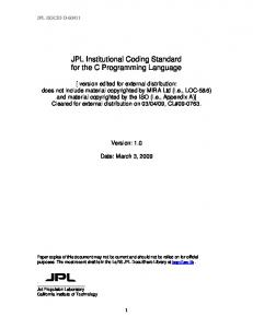
Fig1. MPEG-4 visual profile and visual tools.
2. MPEG-4 VISUAL PROFILE MPEG-4 follows the concept of “Profile” in which the lower layer profile is a subset of a higher layer profile. This means that the higher layer decoder can decode all of the bitstream created by the lower layer encoder. This hierarchical model is also called “onion ring model.” In MPEG-4, “Profile ” contains “Object Type”, a set of tools for several targeted applications. The list of “MPEG-4 Visual Profiles” and the related “Object Types” are as follows. (1)Simple Profile: Simple Object Type (2)Core Profile: Simple Object Type, Core Object Type (3)Simple Scalable Profile: Simple Object Type, Simple Scalable Object Type (4)N-bit Profile: Simple Object Type, Core Object Type, N-bit Object Type (5)Main Profile: Simple Object Type, Core Object Type, Main Object Type, Scalable Still Texture Object Type (6)Scalable Still Texture Profile: Scalable Still Texture Object Type “Simple Profile” is targeted for applications of mobile communication and the Internet. “Core Profile” is for PC applications. “Main Profile” is designed for higher resolution images. “Simple Scalable Profile” is suitable for applications that experience time-varying transmission channel environments. “N-bit Profile” is
mainly used for satellite surveillance applications. Many new coding techniques have been introduced to achieve new coding functions in MPEG-4. Intra, Predicted and Bi-directionally predicted Video Object Planes are the basic approaches to cope with arbitrary shaped images that differ from the conventional square ones. I-VOP and P-VOP can be used in “Simple Profile” where as B-VOP can be used in “Core Profile”. Binary/Grayscale alpha plane can represent levels of transparency when two or more objects overlap. Binary alpha is used in “Core Profile” where as grayscale alpha can be used in “Main Profile”. For enhanced error robustness, “Simple Profile” offers re-synchronization marker, reversible variable length code (VLC) and data partitioning. “Sprite” is one of the coding tools in “Main Profile”. The MPEG-4 standard was design on the assumption that “Sprite” is provided in a certain way. How to generate “Sprite” lies outside the scope of MPEG-4. Wavelet still image coding can provide a graceful degradation for scalable image representation. In the next section, we will focus on MPEG-4 “Sprite” coding used in combination with automatic “Sprite” generation.
Conventional coding
Sprite coding
Foreground video object (MPEG-4 Object coding) Segmentation
Composed image Video sequence Background sprite (MPEG-4 sprite coding)
Background video object
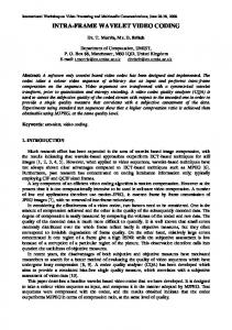
Fig2. Conventional coding vs. sprite coding.
3. SPRITE CODING
We presume a simple two-layer video object plane model. Each frame can be automatically separated to foreground and background VOPs. Fig.3 overviews
Bitstream
Automatic VOP Definition
VOP 1 Encoding
MUX
3.1 Two-layer video object model
Input
DEMUX
Figure2 shows the difference between conventional coding schemes and MPEG-4 object coding. The left side of the figure presents conventional coding. A video sequence is coded frame by frame using motion compensation to reduce frame redundancy. The right side of Figure 2 presents the typical MPEG-4 object coding process. A video sequence can be divided into several video objects. One of the objects is “Sprite”. These video objects are assembled at the receiver site to recreate the image. Object extraction/segmentation lies outside the standardization issue. Automatic “Sprite” generation from a video sequence is a key point in realizing the “Sprite” coding mode in MPEG-4. A “Sprite” can be viewed as a unified image when there is some camera motion such as panning or zooming. Most sport video scenes have such characteristics. First, we propose a new technique to separate moving foreground objects from panning and zooming video sequences. Next, foreground objects are coded by MPEG-4 arbitrary shaped video coding mode; “Sprite” is coded in still image coding mode. The background image in each frame can be reconstructed by geometric-projection from the “Sprite”. This offers high coding efficiency, i.e. high compression ratio, since most of the background image in the video sequence can be represented by one large sprite image; temporal change is ignored.
VOP 0 Encoding
Bitstream
VOP 0 Decoding Composition VOP 1 Decoding
Output
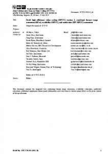
VOP0: Background sprite VOP1: Foreground moving object
Fig3.Two-layer video object model. the coding/decoding model proposed in this paper. On coding side, the image is first split into two layer video objects, namely the foreground object and the background sprite. The background sprite is the background and reflects the camera motion. The foreground object is any moving area not belonging to the background, and all such areas are treated as one object. For example in “soccer” image, the players, the referees and the ball are treated as one foreground object. The foreground object and the background sprite are independent video objects, and the former is converted to free shape code; the latter is subjected to sprite coding in the MPEG-4 Main profile. These isolated bit streams are multiplexed and sent as one. At the receiving side, the bitstream is demultiplexed and the video objects are decoded, superimposed and displayed. If the foreground area is small, the non-foreground area (the background area occupies
Original Image
rotation, c and d denote translation. First, the motion vector for each macro-block is calculated using the block-matching algorithm. Partial derivatives (see Eq. (2) and (3)) of the motion vectors are calculated for each macro-block.
Motion vector calculation Global motion estimation
Global motion
?u ?v ? ? a? ?x ? y ?u ?v ? ? ?b ?y ?x
Provisional sprite generation
Foreground object extraction
Macro-block approximation
Background sprite generation
Background sprite
Foreground object
Fig.4 Automatic two-layer VOP generation algorithm. most of the moving image) can be expressed as one sprite (= static image). Therefore, compression efficiency is expected to be higher than that possible with conventional methods based on MC+DCT. Figure 4 overviews the flow of the two-layer VOP extraction algorithm. The algorithm consists of five parts: motion vector calculation, global motion estimation, provisional sprite generation, foreground object extraction and background(final) sprite generation. 3.2 Global motion detection To generate the sprite, GM should faithfully reflect the camera motion. The typical GM calculation [4][5] yields the MSE (Mean Square Error) between the GM predicted image and the original image [4][5]. Because GM is calculated as the average value of local motion, it does not accurately reflect camera motion. Though documents [10][11] propose a GM calculation method, they do not exclude non-camera motion (outliers). To calculate GM that well reflects camera motion, this paper clarifies the relationship between camera motion and local motion vectors (parallel motion model), and proposes a way to select GM from local motion vector groups. Camera motion can be described using the Hermart transform (four parameters affine) as: ? u ? ? a? b ?? x ? ? c ? ?? ?? ? ?? ???? ?? ? ?? ?? ? v ? ? ? b a??? y ? ? d ? a ? a?? 1
(1)
where (u,v) is the motion vector calculated in each macro-block, (x,y) is the position of the pixel, and {a,a’,b,c,d} is the set of GM parameters to be calculated. a and a’ are scaling parameters, b denotes
(2) (3)
Each partial derivative creates a significant cluster on a line written by Eq.(2) and (3) in each feature space. Here, all blocks with smooth intensity gradation are removed from the target blocks in the GME process, because such motion vectors are not accurate and often concentrate around zero. The centroid of each cluster yields scaling and rotation parameters. In this way, a’and b are detected. Equation (1) can be transformed into ?c? ?? ?? ? ?d ?
?u ? ?? ?? ? ?v ?
? a? b ?? x ? ?? ???? ?? . ? ? b a??? y ?
(4)
Subtracting the scaling and rotation effect from the block-based motion vector according to Eq.(4), yields the transition parameters. Block-based transition parameters are clustered to identify the median values, which well reflect the camera motion. 3.3 Background sprite generation Once camera motion in the sequence is obtained, each frame image can be superimposed considering its size and location. Next, median filtering in the temporal direction is performed to remove the foreground object. Images without foreground object are super- imposed to generate one “Sprite” for the sequence. Applying scaling, rotation and transition parameters to the “Sprite” yields the background image of each frame. To generate a high quality sprite, this paper takes advantage of a conventional temporal median method[10], the overwriting method. Two kinds of sprite are generated: provisional sprite and final sprite. Using the GM calculated from the base frame in the above subsection, we transform the shape of each image and map them on the lattice points of the base coordinate system. We can see that multiple pixels overlap each other. We calculate their median value and take it as the value of that coordinate. This generates the sprite without moving area. However, the sprite generated by the temporal median method tends to be a little fuzzy. We, therefore, use this median-value-based sprite as a temporary sprite to extract the foreground. The overwriting method pastes the pixels as they are on the base frame and so generates a high quality sprite. However, it has a
Background sprite
Original image
Foreground object
Composed image
Fig.5 Generated sprites and foreground objects. problem in that the foreground of the top frame and the foreground object at the edge of each frame remain. Accordingly, after extracting the moving object, we treat the remaining part of the image as the background image and paste the pixels on the base coordinates one by one to generate the final high quality sprite. 3.4 Foreground object extraction Finally, this background image is subtracted from the input image to obtain the foreground object. At first, we calculate the difference image between the original image and the image extracted using the temporary sprite. We binarize this difference image by thresholding and split it into a foreground candidate image and a background image. The foreground candidate image is processed by the foreground shape macro block approximation method (described in the next section), to yield the final foreground image. Because the automatically generated foreground object has complicated contours (many acnodes), its shape is very difficult to predict accurately. This triggers intra coding which increases coding volume. To sidestep this problem, this paper proposes a method that approximates object shape by using macro blocks. Foreground contours are approximated by macro-blocks. This paper proposes two phase macro block approximation. At first, the macro block (contains more than threshold Th1 foreground pixels) is regarded as foreground. All other macro blocks are regarded as background. We then focus on the background macro block adjacent to the foreground macro block from the first macro-block approximation
phase. If more than threshold Th2 (Th2