Future plans for the MDB test area include lowering the SRT temperature to. 2 K and adding ... Dedicated studies were conducted to measure dynamic heat load.
FERMILAB-CONF-11-256-AD
SRF CAVITY TESTING STATUS AND OPERATING EXPERIENCE
W. Soyars, R. Bossert, C. Darve, B. DeGraff, A. Dalesandro, B. Hansen, A. Klebaner, T. Nicol, L. Pei, M. White
Fermi National Accelerator Laboratory Batavia, IL, 60510, USA
ABSTRACT The cryogenic system at the Meson Detector Building (MDB) has now supported over four years of testing of fully assembled SRF cavities. The Horizontal Test Stand (HTS) has tested single, fully dressed 1.3 GHz and 3.9 GHz cavities at 2 K as final qualification prior to their installation into accelerator-ready cryomodules. The MDB cryogenic system has been expanded to support an additional cavity test area, the Spoke Resonator Test (SRT) area, for 325 MHz single-spoke resonators. The SRT area currently supports 4.5 K operations for research and development of the spoke cavities with tuner and coupler. The test area addition required the design and installation of a new cryogenic transfer line extension to reach this second test area and to allow for independent operations of either cavity test system. The cryogenic performance and operational experiences of both cavity test areas, operating individually or simultaneously, will be discussed. The general reliability of operating the closed, subatmospheric helium system free of contaminants will be discussed. Future plans for the MDB test area include lowering the SRT temperature to 2 K and adding an additional Horizontal Test Stand (HTS-2). KEYWORDS: Test facilities, Superconducting RF, ILC, Cryomodule.
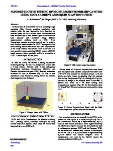
INTRODUCTION Cryogenic fluids, including superfluid helium service, are provided by the Fermilab Meson area Cryogenic Test Facility [1, 2]. This cryogenic system serves the ILC 1.3 GHz cavity Horizontal Test System (HTS) and the adjacent Spoke Resonator Test (SRT) 325 MHz cavity facility in the Meson Detector Building, and is capable of supporting simultaneous operation of both. The HTS has been operational since 2007, while the SRT began service in July 2010. A cryogenic system schematic of the test area is shown in
FIGURE 1. The Capture Cavity II 1.3 GHz cavity was operated at this facility from 20052009, and has been moved for installation into a beam line application. 2 K operations at HTS are achieved, as previously described [2], by large capacity standard rotary vacuum pump handling very low pressure helium gas at room temperature. The system has demonstrated that it can deliver continuous and reliable subatmospheric operation for closed-loop production of superfluid helium for SRF cavities. The standard method of operation calls for continuous on-line purification. However, the system has often been configured with no on-line purification and remains contamination free. HTS is part of the cavity assembly production process, providing quality assurance testing of the fully assembly cavity prior to installation into accelerator-ready cryomodules [3]. Five 3.9 GHz cavities for the DESY FLASH free electron laser facility have been production qualified here. To date, eleven 1.3 GHz have completed their qualification. Some of these cavities were cooled and warmed multiple times at HTS. The nature of HTS cryogenic operation is frequent cycles of cavity installation, cooldown, RF testing, warmup, and cavity removal. The SRT allows for testing a fully assembled 325 MHz superconducting single-spoke cavity dressed with tuner and input coupler. Successful RF testing has been described elsewhere [4, 5]. To date, only one spoke resonator has been available for cryogenic operation and testing. In this phase of the program, SRT thermal cycles and cavity removal have been less frequent that what HTS experiences.
FIGURE 1. The MDB Test Areas System flow schematic.
HORIZONTAL TEST SYSTEM (HTS) The HTS cryostat is a 0.8 m OD, 2.2 m inside-length stainless steel vessel containing 5 K and 80 K thermal shields, fundamental power and higher-order mode RF input couplers, and tuners. See FIGURE 2. It has a unique cavity support and rail system that facilities the frequent installation and removal of cavities for testing. The HTS is capable of cooling a 3.9 GHz or 1.3 GHz cavity to 2 K. HTS Cryogenic Performance During an HTS cooldown, the cavity itself cools down relatively quickly from room temperature to 30 K, in about 1.5 hr. The cavity is then intentionally held at this temperature while other components--the 5 K shield and the stainless steel cart and rail supports--slowly cooldown. The 5 K shield cooldown is limited by an incorrect tubing layout in which counterflow heat exchange from outlet tubing adds heat to the incoming cryogenic cooldown flow. The rail system cooldown is limited by its thermal contact with the cavity, its sole source of cooling. Experience shows that the rail system mass can produce a significant heat load to the helium vessel unless it is given time to cool (experimentally chosen 60 W dynamic heating is available. Subatmospheric Operation HTS has demonstrated that it can reliably run under subatmospheric conditions without contaminating the closed He system. To date, there have been two significant HTS system contamination issues. The primary relief (184 kPa) flange seals, designed for room
temperature, were getting cold when off-nominal pressure resulted in some flow out the lower set point (144 kPa) operational relief due to proximity. Repositioning the primary relief addressed this issue. Also, a flange at the vacuum pump inlet cracked due to vibration. Upgrading the flange and adding flexibility eliminated this problem. Air contamination is monitored at the vacuum pump discharge which is about 100 m away, and at the cryogenic plan which is about 300 m away. The cryogenic system design intent is to run with continuous helium purification at the plant; however, HTS is often run with no active purification with no detrimental contamination occurring.
SINGLE SPOKE RESONATOR TEST (SRT) The Meson Cryogenic System was upgraded to include an additional test cave for the Spoke Resonator Test. This required that a new transfer line and cryogenic distribution system be installed. To maximize operational flexibility, this was built with cryogenic valves to easily isolate either test area for cavity warmup, installation, and subsequent cooldown. The cryogenic distribution system is equipped and instrumented to stay cold in the absence of any test area cryogenic load, to minimize transfer line thermal transients and test area cooldown times. The Spoke Resonator Test (SRT) cryostat is a 1.44 m OD, 1.1 m inside-length stainless steel vessel containing a warm magnetic shield, an 80 K thermal shield, a cavity support system, and a RF input coupler port. It is capable of cooling any of the test configurations to 4.5 K. A more detailed description of the cryostat and its related components can be found in [7]. FIGURE 4 is a picture of the cryostat inside the test facility.
FIGURE 4. The Spoke Resonator Test Area.
SRT Cryogenic Performance Total cooldown time for the SRT from room temperature is about 7 hrs. The process is limited by the heat transfer to the cryogenic helium supply from the cavity helium vessel mass. See FIGURE 5. Static heat leak to 4.5 K is estimated to be about 7 W. The system has demonstrated a capacity to handle about 35 W of dynamic heating, as determined by RF operational experience. This is limited by the cavity pressure allowance of 170 kPa maximum. When RF power is introduced, the helium flow and, consequently, the cavity vessel pressure increase as a function of heating. Cavity pressure becomes the limiting factor for cooling capacity. The cavity’s helium bath pressure is not regulated, but depends on the saturated vapor pressure drop across a 250 m transfer line and the plant’s cryogenic heat exchanger into the refrigerator compressor suction. Simultaneous operation of SRT and HTS has occurred. The main complexity is during an HTS cooldown with SRT cold. The helium transfer line two-phase return pressure will suddenly increase during HTS 5 K shield cooling to LHe conditions. This can lead to temporary pressure rise in the SRT cavity that approaches its relief pressure settings. If relief pressure is exceeded, some helium will be vented to atmosphere.
FIGURE 5. Spoke Resonator Test Cooldown.
CONCLUSION The status of Fermilab’s SRF cavity test program utilizing the Meson cryogenic system has been discussed. The cryogenic operational performance and experience of the two different test areas, the 2 K Horizontal Test System and the 4.5 K Spoke Resonator Test area, has been given. The cryogenic system allows for reliable, cost-effective cryogenic testing for SRF cavity production and development. This includes sustained, continuous subatmospheric operation of a closed helium system with no detrimental air contamination. At the Horizontal Test System (HTS), testing and qualifying SRF cavities prior to their assembly into an accelerator cryomodule will continue. Plans and procurements are underway to install a second Horizontal Test System (HTS-2) here in order to double the dressed cavity testing capacity. At the Spoke Resonator Test area, studies continue in support of 325 MHz single-spoke resonators development. Plans are underway to allow for 2 K cryogenic operation of 325 MHz single-spoke resonators.
ACKNOWLEDGEMENTS This work is supported by the U. S. Department of Energy under contract No. DEAC02-07CH11359. The authors wish to recognize the dedication and skills of the Accelerator Division Cryogenics Department technical personnel involved in the operation of this system.
REFERENCES 1.
2.
3. 4.
5.
6.
7.
Klebaner, A. L. and Theilacker, J. C. “Cryogenics for the Superconducting Module Test Facility”, in Advances in Cryogenic Engineering 51B, edited by J. G. Weisend II, et al, American Institute of Physics, Melville, New York, 2006, pp. 1428-1435. Soyars, W. M. et al “Superconducting Radio-Frequency Modules Test Facility Operating Experience”, in Advances in Cryogenic Engineering 53A, edited by J. G. Weisend II, et al, American Institute of Physics, Melville, New York, 2008, pp. 127-134. Hocker, A. et al “High Power Tests of Dressed Superconducting 1.3 GHz RF Cavities”, Proceedings of 2011 Particle Accelerator Conference, New York, NY, 2011. Webber, R. et al. “First High Gradient Test Results of Dressed 325 MHz Superconductiong Single Spoke Resonator at Fermilab” Proceedings of 25th International Linear Accelerator Conference [LINAC10], edited by M. Ikegami, 2011. Madrak, R. et al. “First High Power Pulsed Tests of Dressed 325 MHz Superconductiong Single Spoke Resonator at Fermilab. “Proceedings of 2011 Particle Accelerator Conference, New York, NY, 2011. DeGraff, B. D. et al “Measurements of SCRF Cavity Dynamic Heat Load in Horizontal Test System”, in Advances in Cryogenic Engineering 55A, edited by J. G. Weisend II, et al, American Institute of Physics, Melville, New York, 2010, pp. 609-614. Nicol, T. HINS Test Cryomod paper "High Intensity Neutrino Source Superconducting Spoke Resonator and Test Cryostat Design and Status", IEEE Transactions on Applied Superconductivity, Volume 19, Number 3, Part II of 3, June 2009, pages 1432-1435.