Cisco IT Best Practices. Survivable Remote Site Telephony Design Guide. Cisco
on Cisco Best Practices. Survivable Remote Site Telephony. Design Guide ...
Cisco IT Best Practices Survivable Remote Site Telephony Design Guide
Cisco on Cisco Best Practices Survivable Remote Site Telephony Design Guide
All contents are Copyright © 1992–2008 Cisco Systems, Inc. All rights reserved. This document is Cisco Public Information.
Cisco IT Best Practices Survivable Remote Site Telephony Design Guide
Table of Contents 1
Introduction .............................................................................................................................. 4
2
Glossary.................................................................................................................................... 4
3
Cisco Remote Office Deployments.......................................................................................... 5 3.1.1 SRST ........................................................................................................................... 6 3.1.2 Cisco Unified Communications Manager................................................................... 8 3.1.3 Communication Endpoints.......................................................................................... 8 3.1.4 Gateways..................................................................................................................... 8 3.1.5 Media Resources....................................................................................................... 10 3.2 SRST Deployment Models.............................................................................................. 11 3.2.1 Dual-Homed/Dual Router Site Topology ................................................................. 12 3.2.2 Single-Homed/Dual Router Site Topology............................................................... 13 3.2.3 Single-Homed/Single Router Topology (Global)..................................................... 14 3.3 SRST Component Configuration..................................................................................... 14 3.3.1 SRST (IOS) Configuration ....................................................................................... 14 3.3.2 IOS Gateways ........................................................................................................... 16 3.3.3 Media Resources IOS.................................................................................................... 25 3.4 SRST Implementation and Operation.............................................................................. 27 3.4.1 SRST Implementation Considerations...................................................................... 27 3.4.2 Operational Considerations....................................................................................... 28 3.4.3 Component Dependencies ........................................................................................ 28 3.4.4 Legal Considerations ................................................................................................ 29 3.4.4.2 Emergency Calls ........................................................................................................ 30
4
References .............................................................................................................................. 30
All contents are Copyright © 1992–2008 Cisco Systems, Inc. All rights reserved. This document is Cisco Public Information.
2
Cisco IT Best Practices Survivable Remote Site Telephony Design Guide
Disclaimer THE SPECIFICATIONS AND INFORMATION REGARDING THE PRODUCTS IN THIS DOCUMENT ARE SUBJECT TO CHANGE WITHOUT NOTICE. ALL STATEMENTS, INFORMATION, AND RECOMMENDATIONS IN THIS DOCUMENT ARE BELIEVED TO BE ACCURATE BUT ARE PRESENTED WITHOUT WARRANTY OF ANY KIND, EXPRESS OR IMPLIED. USERS MUST TAKE FULL RESPONSIBILITY FOR THEIR APPLICATION OF ANY PRODUCTS. THE DESIGN RECOMMENDATIONS AND CONFIGURATIONS PROVIDED IN THIS DOCUMENT ARE SPECIFIC TO CISCO IT REQUIREMENTS. CISCO SYSTEMS DOES NOT ENDORSE OR APPROVE THE CONFIGURATIONS TO BE USED FOR ANY CUSTOMER. THE DESIGN STANDARDS PROVIDED HERE ARE MERELY PROVIDED TO SHARE CISCO IT BEST PRACTICES. EACH AND EVERY CUSTOMER REQUIREMENT WOULD BE DIFFERENT AND HENCE THOROUGH ANALYSIS AND RESEARCH SHOULD BE DONE BEFORE APPLYING ANY DESIGN STANDARD. NOTWITHSTANDING ANY OTHER WARRANTY HEREIN, ALL INFORMATION IS PROVIDED “AS IS” WITH ALL FAULTS. CISCO DISCLAIMS ALL WARRANTIES, EXPRESSED OR IMPLIED, INCLUDING, WITHOUT LIMITATION, THOSE OF MERCHANTABILITY, FITNESS FOR A PARTICULAR PURPOSE AND NONINFRINGEMENT OR ARISING FROM A COURSE OF DEALING, USAGE, OR TRADE PRACTICE. IN NO EVENT SHALL CISCO OR ITS SUPPLIERS BE LIABLE FOR ANY INDIRECT, SPECIAL, CONSEQUENTIAL, OR INCIDENTAL DAMAGES, INCLUDING, WITHOUT LIMITATION, LOST PROFITS OR LOSS OR DAMAGE TO DATA ARISING OUT OF THE USE OR INABILITY TO USE THIS DOCUMENT, EVEN IF CISCO OR ITS SUPPLIERS HAVE BEEN ADVISED OF THE POSSIBILITY OF SUCH DAMAGES.
All contents are Copyright © 1992–2008 Cisco Systems, Inc. All rights reserved. This document is Cisco Public Information.
3
Cisco IT Best Practices Survivable Remote Site Telephony Design Guide
1 Introduction This document specifies Cisco IT infrastructure standards for Survivable Remote Site Telephony (SRST) to support remote-office IP telephony business continuity for Cisco remote offices. It prescribes the use of SRST technology for consistent architecture, design, and deployment in situations that share similar criteria. Before you read this document, Cisco recommends that you read the Cisco IT Remote Office Design Guide(http://www.cisco.com/web/about/ciscoitatwork/network_systems/branch_office_network_design.html),which describes Cisco branch office architecture and design. This design guide describes Cisco IT SRST deployments for single- or dual-router remote offices. The design includes standards for all deployment models as outlined in the centralized call-processing architecture. This design guide also summarizes the base standard configuration for the platform and outlines different solutions depending on the number of devices to be supported in SRST mode. This design guide does not address high-level architecture and design of IP telephony topology, nor does it provide specific IP telephony configuration examples.
2 Glossary The following terms and definitions are used in this document: AA Auto Attendant AAR Automated Alternate Routing CCM Cisco Unified Communications Manager (formerly Cisco CallManager) CMM Communications Media Module. Gateway platform COR Class of Restriction DID Direct Inward Dialing (used with PRI services) DSP Digital Signal Processor EMAN Enterprise Management FSO Field Sales Office FXO Foreign Exchange Office FXS Foreign Exchange Station GK H.323 Gatekeeper with via-zone capabilities Greenfield Completely new site deployment without the requirement to integrate existing systems H.323 ITU-T Recommendation: packet-based multimedia communications systems ICT Inter-Cluster Trunk IPC IP Communicator IPT IP telephony environment MGCP Media Gateway Control Protocol (Cisco Unified Communications Manager controlled gateway protocol) MoH Music on Hold
All contents are Copyright © 1992–2008 Cisco Systems, Inc. All rights reserved. This document is Cisco Public Information.
4
Cisco IT Best Practices Survivable Remote Site Telephony Design Guide
SCCP Skinny Client Control Protocol (used by devices to communicate with Cisco Unified Communications Manager) SRST Survivable Remote Site Telephony. Cisco IOS Software feature that allows call-processing functionality during loss of connection to central Cisco Unified Communications Manager cluster. TCO Total Cost of Ownership VAD Voice Activity Detection VSO Very Small Office
3 Cisco Remote Office Deployments Cisco IT supports more than 300 remote sites in approximately 100 countries. Some of these sites are campus sites, but most are remote branch offices. Remote branch offices connect to the campus sites through the Cisco WAN to hub sites. The Cisco campus and hub sites have dedicated Cisco Unified Communications Manager (formerly Cisco CallManager) clusters. Cisco policy provides that remote users receive the same level of services as employees at campus sites. This approach includes unified communications applications such as voice mail, interactive voice response (IVR), and video services. Only conferencing resources must be locally provisioned at the remote site to prevent multiple streams from unnecessarily traversing the WAN. Hardware Requirements The following addresses the use of the network modules slots and Voice/WAN Interface Card (VWIC) slots at Cisco IT. The available voice slots can be provisioned for primary rate interface (PRI), basic rate interface (BRI), FXO, or FXS connections. Voice lines must be scaled to provide sufficient public switched telephone network (PSTN) connectivity for remote offices. Because many variables determine how to size the PSTN connectivity for a site (for example, business function and cost), this issue is addressed on a site-by-site basis. The standard modules necessary for provisioning PSTN connectivity based on site SRST capacity are described later in this document. When defining which deployment model best suits an office to ensure that endpoint quantities fall within these SRST limits, the design addresses sites with no more than 80 percent of the maximum phones supported in SRST across both routers on the Cisco ISR 3845 platform. SRST is configured on one or both routers depending on the number of endpoints to be supported, and with PSTN connectivity divided across both routers where possible. Based on IT remote office standards, this design defines three configurations that can be applied to remote sites with the following criteria:
Dual WAN router remote site – Single SRST (configured on a single router) Survivable endpoint total is below 576
Dual WAN router remote site – Dual SRST (configured on both routers) Survivable endpoint total exceeds 576 Survivable endpoint total is below 1152
All contents are Copyright © 1992–2008 Cisco Systems, Inc. All rights reserved. This document is Cisco Public Information.
5
Cisco IT Best Practices Survivable Remote Site Telephony Design Guide
Single WAN router remote site – Single SRST Survivable endpoint total is below 576
Note: *Figures are based on Cisco IOS Software Release 12.4.3 SRST 3.2 with Cisco ISR 3845 routers as WAN gateways. Consult www.cisco.com for the most recent updates based on latest versions.
In dual router offices, configuring SRST across both routers effectively increases the SRST capacity to 1152 when configured on the Cisco IT standard Cisco ISR 3845 router. This configuration requires splitting a site’s devices into two logical groups within Cisco Unified Communications Manager administration with separate SRST references to help load balance the failover of endpoints between the two routers. Using dual Cisco 3845 routers for a large office solution imposes strict limitations, namely PRI capacity and WAN connectivity, which should be investigated prior to deployment. If critical business requirements at a site warrant a dedicated cluster, Cisco IT analyzes the individual requests before approving this design. SRST Components SRST is a Cisco IOS Software capability that acts as a backup call-processing agent for Cisco Unified Communications Manager and provides a subset of voice capabilities if the connection to the central Cisco Unified Communications Manager cluster fails. SRST is deployed as standard to all remote offices using the centralized call-processing model to help ensure greater resilience and reliability for the supported clients. IOS and hardware dependent, SRST can currently support a maximum of 1440 endpoints, although Cisco IT recommends reducing this amount by 80 percent to account for an anticipated CPU increase introduced by future IOS features. Different deployment models are tailored to suit other site capacities below this figure. Cisco IT’s SRST standards for a Cisco remote office recommend that a remote site, at a minimum, must support the following capabilities in SRST: Provide inbound and outbound PSTN connectivity to all phones at a remote site Reroute undefined DID extensions to reception/switchboard Provide acceptable PTT calling party CLI on outbound calls Non-integrated voice mail over PSTN for messages button Call forward busy/no answer to: First choice - voice mail (where possible) Second choice - reception/switchboard Date and time Eight-digit translation to PSTN format for internal support services MoH locally streamed from SRST router Inter-digit and busy timeout values
3.1.1 SRST Under normal operations, when the WAN is available, the centralized Cisco Unified Communications Manager does all of the call routing. At that point, only the POTS dial peers for the PSTN interface (PRI/BRI/FXO) are used for external call routing, and then only for incoming calls from the PSTN, and if present, dial peers for FXS fax stations. E-phone dial peers (dial peers in the SRST routers for phones) are not active, because the phones are not registered with the SRST router. During this time, All contents are Copyright © 1992–2008 Cisco Systems, Inc. All rights reserved. This document is Cisco Public Information.
6
Cisco IT Best Practices Survivable Remote Site Telephony Design Guide
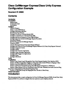
IP phones at the central and remote site behave in the same way, registering with one of the Cisco Unified Communications Managers at the central site, as determined by the Cisco Unified Communications Manager group configured for each phone (primary, secondary Cisco Unified Communications Managers). When a WAN outage occurs, Skinny Client Control Protocol (SCCP) phones detect TCP keepalive timeouts (default keepalive intervals 30 seconds) to all configured Cisco Unified Communications Managers, and fail over to SRST by sending a registration for each device to the SRST router. This triggers the SCCP SRST feature (e-phone) to enable POTS dial peers for each directory number registered. It is only at this time that all call routing decisions move to the SRST gateway. Figure 1 shows a basic call from a remote site to the central site before and after a WAN outage. Prior to the outage, all of the call signaling goes through the Cisco Unified Communications Manager (shown in green). Figure 1 SRST Call Routing
WAN Link
PRI
PRI
During the outage (shown in red), VoIP call signaling terminates at the SRST router, and the call is routed through the PSTN to the central site. The SRST feature becomes active as soon as the phone detects that it has lost its connections to all Cisco Unified Communications Managers, including the ones configured in the redundancy group. At this point the clients will see the default display message for IP phones in fallback mode: “CM Fallback Service Operating.” Calls in progress to local PSTN services are survivable during failover. IP phones periodically attempt to re-establish a connection with the primary Cisco Unified Communications Manager based on response acknowledgments to keepalives at 30-second intervals. When a connection is re-established with the primary Cisco Unified All contents are Copyright © 1992–2008 Cisco Systems, Inc. All rights reserved. This document is Cisco Public Information.
7
Cisco IT Best Practices Survivable Remote Site Telephony Design Guide
Communications Manager, Cisco IP phones automatically cancel their registration with the SRST router.
3.1.2 Cisco Unified Communications Manager Cisco Unified Communications Manager is the main call-processing agent for remote site telephony while WAN connectivity between the main, central cluster, and remote site is available. Cisco INS IT opted for the centralized call-processing model to reduce server count and associated total cost of ownership. It provides centralized call-processing functions for remote site devices as well as applications and services such as video, security, and XML applications. This document focuses only on the Cisco Unified Communications Manager configuration that is integral to deploying this SRST standard.
3.1.3 Communication Endpoints All communication endpoints deployed at sites using SRST should have SRST support so that the endpoints can re-register to the SRST routers in the event of a WAN outage. If a certain endpoint does not have SRST support, this limits its application to noncritical uses that can tolerate outages or service unavailability. Cisco IT has standardized on desktop phones and conference room phones with full SRST support.
3.1.4 Gateways Remote office gateway components comprise four main categories: • Analog station gateways (FXS) • Digital trunks to PSTN (PRI) • Digital trunks to PSTN (BRI) • Analog trunk to PSTN (FXO)
3.1.4.1 Analog Station Gateways (FXS) The Foreign Exchange Station (FXS) gateway is the interface on a VoIP device for connecting directly to analog devices, such as faxes and modems, and supplies ring, voltage, and dial tone. These interfaces terminate to FXS modules in the SRST router itself or on a VG224 if the router does not provide sufficient capacity. Cisco IT chooses the module type based on the quantity of analog ports required to support the analog devices at a remote site and the type of site being provisioned. Recommended for dual router FSO; FXS/FXO modules include: EVM-HD-8FXS/DID EM-HDA-8FXS EM-HDA-6FXO EM-HDA-3FXS/4FXO These modules can provide up to 24 FXS termination points for analog devices based on using one slot (slot 4) on a single SRST router. This capacity can be doubled using slot 4 in both routers.
All contents are Copyright © 1992–2008 Cisco Systems, Inc. All rights reserved. This document is Cisco Public Information.
8
Cisco IT Best Practices Survivable Remote Site Telephony Design Guide
Recommended additional FXS device: VG-224 (24 FXS) – External to WAN router In sites where the numbers of required FXS devices are greater, and/or recommended cable lengths are exceeded between the WAN routers and FXS device, VG-224 devices can be deployed. This IOS device can support up to 24 FXS devices. Recommended for single router VSO; FXS/FXO modules include: VIC-4FXS/DID in VWIC slot 4
Note: Max. cable lengths (100BaseT IEEE 802.3u) 100BaseT4 Category3 or 4 = 100 meters (4 pair) 100BaseTX Category5 = 100 meters (2 pair) Category 3, 4, or 5 (4 pair) = 100 meters
3.1.4.2 Digital Trunks to PSTN (PRI/BRI) Digital trunks used to connect to PSTN are favored over analog-based devices and fall into two categories: primary rate interface (PRI) and basic rate interface (BRI). PRI is a type of ISDN service designed for larger remote offices. A PRI consists of 30 B-channels (23 in the United States) and one D-Channel, and is transmitted through an E1 (EMEA, APAC, India and Japan) or T1 (United States). For smaller remote sites, a single or multiple BRI is used, which only contains two B-channels and one D-channel. Both gateway types provide features such as DTMF support for dial tone and fax/modem support, and use protocols such as MGCP, H.323, and SCCP for local call processing. In most cases, both the BRI and PRI interfaces have associated Direct Inward Dial (DID) capabilities, allowing internal office extension ranges to be assigned to one or more trunks and therefore creating the ability to dial individual extensions from the PSTN. Where individual DID’s are not available, a single main office DID is required and associated to the trunks that terminate to reception, switchboard, or AA, and then internal NON-DID extensions are accessed through one of these services. Field Sales Office dual router recommendations for PRI digital trunk termination. Cisco IT includes a VWIC-(1 or 2)-MFT-E1 / T1, where T1 is the U.S. standard and E1 covers the rest of the world. These are placed in the main internal motherboard’s VWIC slot 1 or 2, allowing for up to four PRI connections per router. VWICs are provisioned across both routers, regardless of whether PRIs are spread between both devices to provide a redundant module if one fails. For small offices, the BRI module VIC2-2BRI-NT/TE is considered a supported exception. It is rarely required because sites that meet minimum requirements for this design are large enough to warrant either a T1 or E1. If used, they are placed in the main board’s slot 1 or 2 of SRST gateway 2, allowing for up to four BRI connections per router (with additional connections being distributed to gateway 1). Very Small Office single router recommendations for PRI/BRI digital trunk termination. Cisco IT includes VWIC-(1 or 2)-MFT-E1/T1 with 2 x PVDM2-64’s on the motherboard. If needed, the VWIC slots are provisioned with VIC2-BRI-NT/TE and VIC2-4FXO.
All contents are Copyright © 1992–2008 Cisco Systems, Inc. All rights reserved. This document is Cisco Public Information.
9
Cisco IT Best Practices Survivable Remote Site Telephony Design Guide
3.1.4.3 Analog Trunk to PSTN (FXO) A Foreign Exchange Office (FXO) gateway is used for trunk or tie-line connections to PSTN, also providing ring, voltage, and dial tone. As a best practice, Cisco IT uses this type of gateway in a remote office environment where BRI or PRI connections are not available. On a single router, the hardware listed above (Analog Station Gateways 4.1.4.1) at this time supports up to 10 FXO connections, although this would only leave eight FXS terminations available. Where required, the EM-HDA-3FXS/4FXO is used for voice backup on gateway 1 and extra FXS capacity, although an additional EVM-HD-8FXS is necessary to house the submodule. Alternatively, a VIC2-4FXO on the main board (slot 1 or 2) of SRST gateway 1 can also accommodate this requirement if additional FXS capacity/redundancy is not required. In the United States, remote sites are configured with backup voice lines to provide a level of redundancy if the primary voice link fails. The number of redundant lines required depends on the total amount of traffic or users at a location and the physical layout of the site (multiple buildings, floors, contiguous space, etc.). In most cases, four FXO lines are provisioned in sites that share PSTN termination facilities with other companies within the same building. These situations tend not to provide reliable and adequate power redundancy. FXO lines are not dependent on local power and, as such, remain available during a power outage.
3.1.5 Media Resources The following media resources provide supplementary services to remote sites. Some of these resources are delivered at the remote site via local hardware, while others are provisioned centrally at the hub site. • Conferencing • MoH • Transcoding Local DSP resources are needed in remote sites to provide conferencing capabilities to the IP phones in that location. IP phones can then initiate ad-hoc conference calls and support a limited number of participants (up to six as defined in the service parameters of the Cisco Unified Communications Manager cluster). Hardware conference bridge resources are required to merge and deliver the different voice streams. Using centralized resources for this task would result in voice streams crossing the WAN unnecessarily and therefore consuming a remote site’s limited bandwidth. On the Cisco ISR 3845 voice gateway, DSPs for standard voice termination for the voice trunk groups are shared with conferencing resources. Single Router Very Small Office – Single SRST 2 x PVDM2-64’s Dual Router Field Sales Office – Single SRST (SRST configured on a single router) 2 x PVDM2-64’s provisioned on both routers Dual Router Field Sales Office – Dual SRST (SRST configured on both routers) 4 x PVDM2-64’s provisioned on both routers
All contents are Copyright © 1992–2008 Cisco Systems, Inc. All rights reserved. This document is Cisco Public Information.
10
Cisco IT Best Practices Survivable Remote Site Telephony Design Guide
The dual SRST 3845 must contain four PVDM2-64’s installed on the main board per SRST enabled router to provide both conferencing resources and DSP banks to accommodate normal voice termination. DSP provisioning is an extremely complex process, and opting for the highest capacity chip set for the dual SRST model greatly simplifies equipment choice. Also, by over-provisioning in this manner, Cisco IT allows for future office expansion and provides adequate redundancy in case a DSP chip-set fails. Figure 2 Cisco ISR 3845 Main Board with 4 x PVDM2 Slots
In both cases, a Media Resource Group (MRG) is configured per site and is assigned as the first option to the devices on that site. This ensures that local resources are used first, and central resources are used only if local resources are not available, Note that Cisco IT standardizes on provisioning hardware conference resources only; no software conference bridges are created on Cisco Unified Communications Manager servers. Because most inter-site voice traffic uses G.729 to enable a more economic use of bandwidth, transcoding resources are provided at the core sites only. Transcoding G729 to G711 is typically required only for centralized application servers (that is, IVRs, Cisco Unity voice mail). Allocating the core sites’ DSPs on the WS-X6608-E1/T1 blade provides these resources. The Music on Hold (MoH) feature provides a music stream to callers who have been put on hold while they are waiting to be transferred to another phone or until the called user is available. The current Cisco call-processing topology provides redundant centralized MoH servers to stream the music to the endpoints using G.711 to provide best audio quality. Currently, the standard best practice is to configure MoH for all remote sites regardless of bandwidth limitations based on the premise that Automated Attendant Routing (AAR) is configured on the cluster. If AAR is not available for a remote site because of a lack of DID functionality or very limited bandwidth, disabling MoH is optional. This is handled on a case-by-case basis.
3.2 SRST Deployment Models The following network diagrams give examples of the different standard topology types in each global theater. Because the transport infrastructure implementations vary within these theaters, the standard remote site voice models also vary slightly. For detailed deployment model topologies and qualifying criteria, refer to the Cisco IT Remote Office Design Standards at http://www.cisco.com/web/about/ciscoitatwork/network_systems/branch_office_network_design.html
All contents are Copyright © 1992–2008 Cisco Systems, Inc. All rights reserved. This document is Cisco Public Information.
11
Cisco IT Best Practices Survivable Remote Site Telephony Design Guide
3.2.1 Dual-Homed/Dual Router Site Topology This network type is based on dual, clear channel leased lines that are sized appropriately to accommodate the remote site. In normal operations, traffic is sent across the primary link and the backup is active only if the primary link fails. PSTN redundancy can be provisioned in numerous ways, depending on the environment where the circuits terminate. Spare VWIC voice modules must be installed on the secondary gateway (gw1) to provide redundancy if the hardware to which the PSTN circuits terminate on gateway 2 fails. In this scenario, the circuit can easily be repatched to gateway 1. Repatching in this way, although not desirable, is the method that has the fewest impacts, is the most cost effective, and requires minimal skill level. The only other option is PSTN over provisioning, which is cost prohibitive because of the very low risk of hardware failure. Allocating audio and video bandwidth in line with the QoS design recommendations, blocking SCCP traffic on the backup link if it is smaller than the primary link to prevent oversubscription if the primary link fails are other best practices followed for this design. Figure 3 Dual-Homed/Dual Router Site Topology
Centralized Call Processing Cluster Cisco UCM - 1 Cisco UCM -2
PSTN
Dual-Homed Connection E1 Voice PRI/BRI
WAN GW1
WAN GW2
100TX Cross Over Routed /30
100 TX
100 TX
LAN
Fax VG224 connecting into Layer 2 is used for additional FXS ports
All contents are Copyright © 1992–2008 Cisco Systems, Inc. All rights reserved. This document is Cisco Public Information.
12
Cisco IT Best Practices Survivable Remote Site Telephony Design Guide
3.2.2 Single-Homed/Dual Router Site Topology This topology is used for locations where ISDN backup is still predominantly used for a backup link and the backup is far smaller than that of the primary. Some of the best practices followed include -Allocating audio and video bandwidth in line with the QoS design standards, blocking voice and video traffic on the backup link based on the size of the largest single link and installing spare VWIC voice modules on the secondary gateway 1. Figure 4 Single-Homed/Dual Router Site Topology Centralized Call Processing Cluster Cisco UCM 1 Cisco UCM 2
Primary WAN Link
PSTN
ISDN Backup Link E1 Voice PRI/BRI
WAN GW1
WAN GW2
100TX Cross Over Routed /30
100 TX
100 TX
LAN
Fax VG224 connecting into Layer 2 is used for additional FXS ports
All contents are Copyright © 1992–2008 Cisco Systems, Inc. All rights reserved. This document is Cisco Public Information.
13
Cisco IT Best Practices Survivable Remote Site Telephony Design Guide
3.2.3 Single-Homed/Single Router Topology (Global)
Fax
3.3 SRST Component Configuration 3.3.1 SRST (IOS) Configuration The following commands outline the standard SRST features, function, and usage as applied inside Cisco IT. The commands are based on the following IOS and SRST version: Cisco IOS Software Release 12.4.3 SRST version 3.2 IOS cmd example From global configuration mode, enter the following commands: Translation-rule 1 Rule 1 < Internal Support number) if required>
US SRST COnfiguration– rule 1 12345678 94081234567
Comment/Usage Maintains Internal support speed-dial on IP phone by replacing 8-digit Internal Technical Support speed-dial with PSTN-qualified equivalent in SRST conditions.
All contents are Copyright © 1992–2008 Cisco Systems, Inc. All rights reserved. This document is Cisco Public Information.
14
Cisco IT Best Practices Survivable Remote Site Telephony Design Guide
Translation-rule 2 Rule 1 8XYZ
Rule 2 840812345678
(Where XYZ represents the remote sites 3 internal prefix)
Call-manager-fallback
Strips 8 plus 3 digit site code from calling number on calls to PSTN and replaces with DID prefix to present recognizable digits to preserve calling party CLI. Modify rule to suit PTT requirement. Enters CallManager fallback mode
From the call-manager-fallback configuration mode. enter the following commands: Usually configured to point to the ip source-address port 2000 strict-match loopback address max-ephones Max-ephones 576 3845–576 max-dn numbers to be supported in SRST mode. Max-dn 960 3845–960 Sets the huntstop attribute for the dial peers associated with the Cisco IP huntstop phone dial peers created during CallManager fallback. Prevents dial-peer hunting. Applies translation rule to Internal Translate called Translate called 1 Technical support speed-dial (see above) Applies translation rule to calling party translate calling Translate called 2 number (see above) Adds PSTN qualified voice-mail voicemail Voicemail 4081234567# (To speed up the dialing of the number add a # at the end of the string.) Provides Music on Hold in SRST mode. moh music-on-hold.au (File must be stored in Flash) Provides standard 24-hour time display o time-format time-format 24 endpoint in SRST mode. Date-format dd-mm-yy Provides standard date format display date-format dd-mm-yy on endpoint in SRST mode. Sets call fwd all to reception number NOTE: When forwarding to central voicemail system the Redirecting Call-forward busy Number IE Delivery--Inbound must be 8XYZ checked on the centralized gateways for access to Cisco Unity via the PSTN during fallback.
call-forward noan 8XYZ timeout 12
call-forward noan 81234567
Sets call fwd noan to reception number. NOTE: When forwarding to central voicemail system the Redirecting Number IE Delivery--Inbound must be checked on the centralized gateways for access to the Unity via the PSTN during fallback.
All contents are Copyright © 1992–2008 Cisco Systems, Inc. All rights reserved. This document is Cisco Public Information.
15
Cisco IT Best Practices Survivable Remote Site Telephony Design Guide
Enables PSTN access in SRST Transfer-pattern T
transfer-pattern 0T
Transfer-pattern
transfer-pattern 10..
Timeouts interdigit Timeouts busy
transfer-pattern—String of digits for permitted call transfers. Wildcards are permitted. Enables 4-digit dialing in SRST transfer-pattern—String of digits for permitted call transfers. Wildcards are permitted.
Timeouts interdigit 8 Timeouts busy 12
alias 1 to
alias 1 81234… 81234567
Limit-dn 7960
Limit-dn 7960 1
Limit-dn 7970
Limit-dn 7960 1
Transfers calls to undefined numbers within office DID range to switchboard. command obsoletes the default-destination command and should be used in preference. NOTE: not used when configuring SRST across dual routers. Necessary only in countries to prevent VoIP-only line registering to the SRST router. (for example, a legal requirement in India) Necessary only in countries to prevent VoIP-only line registering to the SRST router (for example, a legal requirement India).
3.3.2 IOS Gateways 3.3.2.1 H.323 Gateway IOS - Contains standard configuration for H.323 gateway in IOS example IOS cmd From global configuration mode, enter the following commands:
Comment/Usage
isdn switch-type
Sets switch type, check with local PTT.
voice class codec codec preference codec preference codec preference
isdn switch-type primary-net5
Sets codec handling NOTE: The order varies by region. Order of codecs should match that of the region where the site is located.
1 1 g711alaw 2 g729r8 3 g711ulaw
Sets timeout for dial peer failover, values can vary. Default value is 5 Sets loopback address as source interface for H.323 signaling. NOTE: Select 0 for APAC and US. Select 5 for EMEA as MPLS SNMP is monitored on loopback 0.
voice class h323 1 h225 timeout tcp establish interface Loopback h323-gateway voip interface h323-gateway voip bind srcaddr
To set the controller E1: Controller E1
controller E1 1/0
Sets controller for PRI/ fractional PRI
pri-group timeslots
pri-group timeslots 1-31
For a full PRI enter E1 1-31as timeslots.
All contents are Copyright © 1992–2008 Cisco Systems, Inc. All rights reserved. This document is Cisco Public Information.
16
Cisco IT Best Practices Survivable Remote Site Telephony Design Guide
Framing
Framing CRC4
For a fractional PRI define the first and last timeslot in use. Sets Framing for PRI. Check with local PTT for details.
To set the controller T1: Controller T1
controller T1 1/0
pri-group timeslots
pri-group timeslots 1-24
Sets controller for PRI/ fractional PRI For a full PRI enter T1 1-24 as timeslots. a fractional PRI define the first and last timeslot in use. Check with carrier. Configure when framing loss seconds are increasing. Ensure the framing format configured on the port matches the framing format of the line. Look for "Framing is {ESF|SF}" in the show controller t1 output.
framing
Check with carrier. Configure when line code violations are increasing. Ensure the line coding configured on the port matches the line coding of the line. Look Line Code is {B8ZS|AMI} in the show controller t1 output. Check with carrier. Disables yellow detection and generation in the event of frame loss.
linecode
no yellow generation no yellow detection
To set a BRI interface: interface BRI no ip address description < voice/data type circuit id>
interface BRI no ip address Voice BRI PTT052
Accept inbound ISDN voice calls from PSTN. Check with carrier. Some countries may require an alerting message to be sent before sending the connect message. Check with carrier. Some countries may require a sending complete IE to be sent in the setup message to indicate the entire number is resolved.
isdn incoming-voice voice
isdn send-alerting
isdn sending-complete
To set a PRI interface: interface Serial no ip address description isdn incoming-voice voice
interface Serial no ip address
See above. See above. See above. See above.
isdn send-alerting isdn sending-complete
To configure voice port: voice-port
compand-type a-law (Non US BRI only)
voice-port 1/0:15
Optional. Cisco IOS will default the PCM companding on BRI voice ports to u-law. If the VIC-2BRI-NT/TE is used in locations outside of North America, a-law PCM coding must be selected. NOTE: For PRI this command is not required.
All contents are Copyright © 1992–2008 Cisco Systems, Inc. All rights reserved. This document is Cisco Public Information.
17
Cisco IT Best Practices Survivable Remote Site Telephony Design Guide
cptone
cptone Russia
Specifies a regional analog voice-interface-related tone, ring, and cadence setting.
To configure PSTN access: dial-peer voice 10 pots description-voice BRI/PRI
Sets dial-peer identifier for PSTN access. description-voice PRI 31203571xxx/CID WOD41684
preference 1
destination-pattern T
destination-pattern 0T
Sets assigned interface type, DID range, and circuit id to help troubleshooting. Sets dial-peer preference for the PSTN interface. Preference for subsequent PSTN interfaces should be increased by an incremental value of 1. Sets destination pattern for external PSTN access utilizing the remote sites PSTN access code. Test with carrier. Necessary if voice call send-alert doesn’t provide ringback. Test with carrier. Necessary if voice call send-alert doesn’t provide ringback. Test with carrier. Necessary if voice call send-alert doesn’t provide ringback.
progress_ind alert enable 8 progress_ind progress enable 8 progress_ind connect enable 8 direct-inward-dial
Associates POTS dial-peer to PSTN interface To configure VoIP dial-peer to connect to primary/secondary Cisco Unified Communications Manager - requires 2 VoIP dial-pe Sets dial-peer label for Cisco Unified Communication Manager access. VoIP dial-peer voice 200 voip peer id numbers should start at 200, with subsequent peers increasing by a value of 1. Preference of VoIP dial-peer for primary Cisco Unified Communication Manager subscriber. Preference for subsequent preference 1 secondary Cisco Unified Communication Manager subscribers should be increased by an incremental value of 1 if destination patterns match. Sets destination pattern for inbound access utilizing the remote sites 8+7 digit number range. destination-pattern 81234… destination-pattern 8XYZ…. NOTE: Splitting of ranges between clusters requires the creation of extra VoIP dial peers with more specific matches. Applied to VoIP dial-peers to stop outbound calls from Cisco Unified Communications Manager to router incoming called-number matching the default ‘hidden’ dial-peer that enables VAD. VAD should be disabled on both inbound and outbound call legs. Applies codec handling to inbound VoIP voice-class codec 1 peer, defined above. voice-class h323 1 Applies timeout settings for dial-peer port
port 1/0:15
All contents are Copyright © 1992–2008 Cisco Systems, Inc. All rights reserved. This document is Cisco Public Information.
18
Cisco IT Best Practices Survivable Remote Site Telephony Design Guide
session target ipv4:
dtmf-relay h245-alphanumeric
tone ringback alert-no-PI
progress_ind setup enable 3
ip qos dscp ef media ip qos dscp cs3 signaling
fax rate [bytes bytes]
fax rate voice
no vad
failover, defined above. Defines target destination to Primary Cisco Unified Communications Manager on first VoIP peer and secondary Cisco Unified Communications Manager on the second. Helps relay DTMF tones without distortion created by Voice codec’s. The "h245-alphanumeric" option simply relays DTMF tones as ASCII characters. Test with carrier. Generates automatic ringback for the caller when no Progress Indicator (PI) alert has been received over the H.323 network. Test with carrier. Forces the gateway to generate ringback. NOTE: Can be used if ringback is not generated due to ISDN issue where ringback is not generated when calls originate from an international location. Ringback for international calls is usually generated on the terminating device. Sets correct QoS value for RTP stream on inbound calls. Sets correct QoS value for call signaling on inbound calls. Sets maximum fax transmission speed. Voice option specifies highest fax transmission rate allowed by the voice codec rate. Turns off VAD
To configure number expansion on the router: num-exp
num-exp 123456... 567891..
num-exp
num-exp 1… 83121…
Expands digits received from PSTN to 8-digit DID number. Expands 4/5 digit dialing to 8-digit endpoint in SRST. If 4/5 digits are received from PSTN then this line becomes redundant.
Optional dial-peer configuration if SRST is configured across both routers. Configure dial-peers on both routers as required.: See above.
dial-peer voice 202 voip preference 3
preference 3
destination-pattern 8XYZ….
destination-pattern 812345…
incoming called-number . voice-class codec 1 voice-class h323 1 session target ipv4:
Preference must be a higher number than normal VoIP peers. Sets generic remote site pattern to match to undefined endpoint dial-peers on originating router in SRST mode. See above. Defines target destination to send calls to undefined endpoint dial-peers on originating router in SRST mode.
All contents are Copyright © 1992–2008 Cisco Systems, Inc. All rights reserved. This document is Cisco Public Information.
19
Cisco IT Best Practices Survivable Remote Site Telephony Design Guide
dtmf-relay h245-alphanumeric ip qos dscp ef media ip qos dscp cs3 signaling fax rate voice no vad
See above.
Optional dial-peer configuration if PSTN access is configured across both routers Configure dial-peers on both routers as required: dial-peer voice 507 voip
preference 4
destination-pattern T incoming called-number . voice-class codec 1 voice-class h323 1
preference 4
See above. Preference must be a higher number than existing POTS peers residing on the router itself unless router contains no PSTN interfaces. For example, SRST configured across both routers, but PSTN access is not.
destination-pattern 0T
See above. Defines target destination of the other router to increase PSTN capacity.
session target ipv4: dtmf-relay h245-alphanumeric ip qos dscp ef media ip qos dscp cs3 signaling fax rate voice no vad
See above.
NOTE: Configure ringback tone on ISDN-H.323 VoIP call: If no ringback tone is heard, refer to the Cisco.com document: Troubleshooting No Ringback Tone on ISDN-VoIP (H.323) Calls
3.3.2.2 FXS Gateway IOS - Contains standard configuration for FXS gateways on a Cisco IOS router example IOS cmd From global configuration mode, enter the following commands: Dial-peer voice pots 100 Description
Description fax M.5-5.7
Destination-pattern
81234567
Port
Port 2/0/0
IOS cmd on VG224
example
Comment/Usage Numeric dial-peer identifier, starting at 100 each subsequent FXS peers should increment by a value of 1. Device type and location helps troubleshooting. FXS devices 8-digit DN. Only faxes should be assigned a DID number if possible. In no circumstances should a modem be assigned a DID DN. FXS interface
Comment/Usage
From global configuration mode, enter the following commands: voice class codec 1
codec preference 1 g711alaw
Sets codec handling NOTE: The order varies by region. Order of codecs should match that of the region where the site is located.
All contents are Copyright © 1992–2008 Cisco Systems, Inc. All rights reserved. This document is Cisco Public Information.
20
Cisco IT Best Practices Survivable Remote Site Telephony Design Guide
codec preference 2 g729r8 codec preference 3 g711ulaw
Sets timeout for dial peer failover, values vary. Default value is 5.
voice class h323 1
h225 timeout tcp establish interface FastEthernet0/0
Connection to switch
description ip address h323-gateway voip interface h323-gateway voip bind srcaddr duplex full speed 100 interface FastEthernet0/1 description No ip address ip route 0.0.0.0 0.0.0.0
To be able to send packets out
To configure voice port: voice-port
cptone
voice-port 2/0
cptone Russia
Specifies a regional analog voiceinterface-related tone, ring, and cadence setting.
To configure VoIP dial-peer to connect to primary/secondary Cisco Unified Communications Manager: Sets dial-peer label for Cisco Unified Communication Manager access. dial-peer voice 450 voip
preference 1
destination-pattern 8XYZ….
incoming called-number
destination-pattern 81234…
Preference of VoIP dial-peer for primary Cisco Unified Communications Manager subscriber. Preference for subsequent secondary Cisco Unified Communications Manager subscribers should be increased an incremental value of 1 if destination patterns match. Sets destination pattern for inbound access utilizing the remote sites 8+7 digit number range. NOTE: Splitting of ranges between Clusters requires the creation of extra VoIP dial peers with more specific matches. Applied to VoIP dial-peers to stop outbound calls from Cisco Unified Communications Manager to router matching the default ‘hidden’ dial-peer that enables VAD.VAD should be disabled on both inbound and outbound call legs.
All contents are Copyright © 1992–2008 Cisco Systems, Inc. All rights reserved. This document is Cisco Public Information.
21
Cisco IT Best Practices Survivable Remote Site Telephony Design Guide
voice-class codec 1
Applies codec handling to inbound VoIP d peer, defined above.
voice-class h323 1
Applies timeout settings for dial-peer failover, defined above. Defines target destination to primary Cisco Unified Communications Manager first VoIP peer and secondary Cisco Unified Communications Manager on the second. Helps relay DTMF tones without distortion created by voice codecs. The "h245-alphanumeric" option simply relays DTMF tones as ASCII characters.
session target ipv4:
dtmf-relay h245-alphanumeric
Sets correct QoS value for RTP stream on inbound calls.
ip qos dscp ef media
Sets correct QoS value for call signaling on inbound calls. ip qos dscp cs3 signaling
fax rate [bytes bytes]
fax rate voice
Sets maximum fax transmission speed. Voice option specifies highest fax transmission rate allowed by the voice codec rate. Turns off VAD
no vad
dial-peer configuration for SRST (remote sites only): dial-peer voice 202 voip
See above.
description
preference 3
preference 3
Preference must be a higher number than normal VoIP peers. Sets generic remote site pattern to match calls to undefined endpoint dial-peers on originating router in SRST mode.
destination-pattern 8XYZ….
destination-pattern 83121…
voice-class codec 1 voice-class h323 1
session target ipv4:
Defines target destination to send calls to undefined endpoint dial-peers on originating router in SRST mode. EMEA loopback 5; Rest of world – loopback 0 See above.
dtmf-relay h245-alphanumeric ip qos dscp ef media ip qos dscp cs3 signaling fax rate voice no vad
Optional dial-peer configuration if SRST is configured across both routers (remote sites only): dial-peer voice 203 voip See above.
All contents are Copyright © 1992–2008 Cisco Systems, Inc. All rights reserved. This document is Cisco Public Information.
22
Cisco IT Best Practices Survivable Remote Site Telephony Design Guide
description
preference 4
preference 4
Preference must be a higher number than normal VoIP peers. Sets generic remote site pattern to match calls to undefined endpoint dial-peers on originating router in SRST mode.
destination-pattern 8XYZ….
destination-pattern 83121…
voice-class codec 1 voice-class h323 1
Defines target destination to send calls to undefined endpoint dial-peers on originating router in SRST mode. (EMEA – loopback 5; Rest of world – loopback 0)
session target ipv4:
See above.
dtmf-relay h245-alphanumeric ip qos dscp ef media ip qos dscp cs3 signaling fax rate voice no vad
To configure PSTN access, first via primary/secondary Cisco Unified Communication Manager then PSTN router: Sets dial-peer identifier for PSTN access. dial-peer voice 204 voip description
Sets dial-peer preference for the PSTN interface. Preference for subsequent PSTN interfaces should be increased by an incremental value of 1.
preference 1
destination-pattern T
destination-pattern 0T
Sets destination pattern for external PSTN access utilizing the remote sites PSTN access code.
voice-class codec 1 voice-class h323 1
session target ipv4: dtmf-relay h245-alphanumeric
Defines target destination to primary Cisco Unified Communications Manager on first VoIP peer and secondary Cisco Unified Communications Manager on the second. PSTN GW as third (EMEA – loopback 5 if WAN router; Rest of world loopback 0) See above.
ip qos dscp ef media ip qos dscp cs3 signaling fax rate voice no vad
Sets dial-peer identifier for PSTN access. dial-peer voice 206 voip description
All contents are Copyright © 1992–2008 Cisco Systems, Inc. All rights reserved. This document is Cisco Public Information.
23
Cisco IT Best Practices Survivable Remote Site Telephony Design Guide
Sets dial-peer preference for the PSTN interface. Preference for subsequent PSTN interfaces should be increased by an incremental value of 1.
preference 3
destination-pattern T
destination-pattern 0T
Sets destination pattern for external PSTN access utilizing the remote sites PSTN access code.
voice-class codec 1 voice-class h323 1
Defines target destination of the other router to increase PSTN capacity. session target ipv4:
See above.
dtmf-relay h245-alphanumeric ip qos dscp ef media ip qos dscp cs3 signaling fax rate voice no vad
Optional dial-peer configuration if PSTN access is configured across both voip routers: See above. dial-peer voice 207 voip description preference 4
preference 4
destination-pattern T
destination-pattern 0T
voice-class codec 1 voice-class h323 1
Defines target destination of the other PSTN router to increase PSTN capacity. session target ipv4:
See above.
dtmf-relay h245-alphanumeric ip qos dscp ef media ip qos dscp cs3 signaling fax rate voice no vad
To configure the FXS devices with POTS dial-peers: Numeric dial-peer identifier, starting at 100 each subsequent FXS peers should increment by a value of 1.
Dial-peer voice 100 pots
Description
Description fax
Destination-pattern
Device type and location helps M.5-5.7 troubleshooting.
81234567
FXS devices 8 digit DN. Only faxes should be assigned a DID number if possible. In no circumstances should a modem be assigned a DID DN. FXS interface
Port
2/0
All contents are Copyright © 1992–2008 Cisco Systems, Inc. All rights reserved. This document is Cisco Public Information.
24
Cisco IT Best Practices Survivable Remote Site Telephony Design Guide
For remote sites (non campus) configuration on SRST/PSTN routers to enable VG224 in SRST and for local incoming calls: Dial peer for analog device connected to VG224 dial-peer voice 300 voip description to vg224 80529824 destination-pattern 80529824
session target ipv4:
session target ipv4:1.1.1.1
VG224 f0/0 interface IP Address
3.3.2.2.1 FXO Gateway IOS – US Only - Contains standard configuration for FXO (analogue trunk to PSTN) gateways in IOS IOS cmd example From global configuration mode, enter the following commands: voice-port
Comment/Usage
Voice-port 0/1/1
no snmp trap link-status
connection plar
connection plar 81234567
description
description DIDs 123-4561234, 4567
Disables SNMP link trap generation. Converts inbound calls to FXO line DIDs (not associated to office’s main DID range) into main reception number, therefore matching the site’s main DID range.
3.3.3 Media Resources IOS 3.3.3.1 Conferencing IOS IOS cmd example From global configuration mode, enter the following commands: sccp local
sccp local GigabitEthernet4/0.400
sccp ccm identifier 1 version x.y
sccp ccm 10.1.1.1 identifier 1 version x.y
sccp ccm identifier 2 version x.y
sccp ccm 10.1.1.2 identifier 2 version x.y
sccp
Voice-card
Dsp services dspfarm
Voice-card 2
Comment/Usage Sets the local interface that SCCP applications use to register to Cisco Unified Communications Manager Adds primary Cisco Unified Communications Manager subscriber to the list of available servers to which the Cisco voice gateway can register. Adds secondary Cisco Unified Communications Manager subscriber to the list of available servers to which the Cisco voice gateway can register. Enables SCCP and brings it up administratively. Enters voice card configuration mode on the module where DSP farm services are required. Enables DSP farm services for the voice card.
exit
All contents are Copyright © 1992–2008 Cisco Systems, Inc. All rights reserved. This document is Cisco Public Information.
25
Cisco IT Best Practices Survivable Remote Site Telephony Design Guide
Enters DSP farm profile configuration mode to define a profile for DSP farm services. Dsp profile
Dsp profile 1 conference
description
Description local conferencing
codec
codec g711ulaw
codec
codec g711alaw
codec
codec g729ar8
codec
codec g729abr8
codec
codec g729r8
codec
codec g729br8
maximum sessions
maximum sessions 6
dspfarm confbridge maximum sessions
dspfarm confbridge maximum sessions 7
associate application SCCP
No shutdown
NOTE: The profile-identifier and service type uniquely identifies a profile. If the service type and profile-identifier pair is not unique, you are prompted to choose a different profile-identifier.
Specifies the codecs supported by the DSP farm. Repeat this step for each supported codec.
Specifies the maximum number of sessions supported by the DSP farm profile for 3845 platform. Specifies the maximum number of sessions supported by the DSP farm profile for 3745 platform. Associates the SCCP to the DSP farm profile. Enables the profile, allocates DSP farm resources, and associates the application.
exit
sccp ccm group
Description
Description aaagroup
associate ccm 1 priority 1
associate ccm 1 priority 1
associate ccm 2 priority 2
associate ccm 2 priority 2
associate profile register
associate profile 1 register ABCDEFGHIJK
Creates a unique Cisco Unified Communication Manager group and enters SCCP Cisco Unified Communication Manager configuration mode. Cisco Unified Communication Manager group Associates primary Cisco Unified Communication Manager server to the Cisco Unified Communication Manager group and establishes its priority within the group. Associates secondary Cisco Unified Communication Manager server to the Cisco Unified Communication Manager group and establishes its priority within the group. Associates a DSP farm profile to the CallManager group. NOTE: Device-name must match the device name configured in Cisco Unified Communication Manager or profile will
All contents are Copyright © 1992–2008 Cisco Systems, Inc. All rights reserved. This document is Cisco Public Information.
26
Cisco IT Best Practices Survivable Remote Site Telephony Design Guide
not register to Cisco Unified Communication Manager.
3.4 SRST Implementation and Operation 3.4.1 SRST Implementation Considerations When establishing how to implement SRST and determine which cluster a remote site should be registered to, Cisco IT considers several factors: • Closest network path • Cultural considerations • High availability services • Political restrictions • Legal restrictions • Cluster sizing This document assumes a fault-tolerant, highly available network infrastructure with end-to-end QoS for both voice and video traffic. The ITU G.114 recommendation states that the one-way delay in a voice network should be no more than or equal to 150 milliseconds. Edge cases or exceptions that slightly falling outside these recommendations are addressed on a case-by-case basis by the Cisco IT teams. Cultural considerations include the normal work hours per week within a particular country. For example, the standard work week and weekend days may differ in some countries. This can cause issues when major outages are required at hub cluster locations (servicing remote sites in other countries) for upgrades, patching, etc. where outages are preferred on weekends to prevent unnecessary client disruption. High-availability, critical services at a remote site might require a standalone cluster or the migration of those services to a central hub cluster location. Political or military conditions can lead to inadequate network connections or legal restrictions to prevent communication channels. In these cases, remote registration must not be considered, and alternatives such as separate clusters must be investigated. Many countries have yet to establish a legal framework to govern VoIP communication; therefore, it is essential that the Cisco legal department confirms a country’s legal status before implementing VoIP. In countries where voice signaling is legal but VoIP is not, it is possible to register remote sites on the strict condition that VoIP is blocked with appropriate calling between sites rerouted over PSTN.
All contents are Copyright © 1992–2008 Cisco Systems, Inc. All rights reserved. This document is Cisco Public Information.
27
Cisco IT Best Practices Survivable Remote Site Telephony Design Guide
Cisco Unified Communications Manager has hardware limitations governing the total device weight that can be loaded onto the platform; this weight must be considered before registering remote sites. It is prudent to keep a running total of the device/dialplan weight on a cluster to help ensure that the weight is not exceeded, resulting in suboptimal server performance.
3.4.2 Operational Considerations Remote site gateways are monitored similarly to any other voice gateway. Voice availability is considered a critical service and, as such, requires an appropriate level of monitoring for both inbound and outbound PSTN connectivity.
3.4.3 Component Dependencies The Cisco Unified Communications Manager Extension Mobility feature provides limited support in SRST mode (depending on the version Cisco IT has deployed). If clients are logged in from their home site, they will be able to make and receive calls from the PSTN if the DID extension on the phone matches the DID range terminating on one of the SRST routers. If the DID range does not terminate on the SRST router (for example, clients are logged in from a site other than their own or from a logged-off phone), only outbound calling to the PSTN is possible for that device. H.323 IPVC endpoints will not remain survivable during loss of connectivity to the central cluster because they are not Cisco Unified Communications Manager controlled. No support exists within SRST for these devices. Cisco Unified Video Advantage (formerly Cisco VT Advantage) also depends on the centralized Cisco Unified Communications Manager service and, as such, is not available in SRST mode. In the current version supported by Cisco IT, Cisco IP Communicator endpoints and the Cisco Unified IP Phone 7920 are not supported in SRST mode. Due to the mobile nature of these devices, it is not possible to dynamically adopt calling patterns of a site other than that of the client’s home site. With this restriction, there is no guarantee that emergency calling will be routed to the correct destination while clients travel outside their home site. Therefore, a disclaimer explaining the limitations should be signed by the client using this device. FXS, FXO, PRI, and BRI (both H.323 and MGCP) gateways terminating on SRST routers will remain available to same-site clients in SRST mode. All gateways (remote FXS, FXO, PRI, BRI, and ICT) remote to the site entering SRST mode will be unavailable until WAN services are restored. Only local “remote site” conferencing resources are available to clients in SRST, and MoH will stream locally from the SRST router rather than from a central hub location. If SRST capability is necessary across both WAN gateways to increase the amount of supported endpoints, Cisco IT recommends the following guidelines. To help ensure that all endpoints remain contactable in SRST conditions, it is necessary to configure dial-peers between the two routers. The dial-peers facilitate cross router calls between IP phones and inbound and outbound PSTN
All contents are Copyright © 1992–2008 Cisco Systems, Inc. All rights reserved. This document is Cisco Public Information.
28
Cisco IT Best Practices Survivable Remote Site Telephony Design Guide
connectivity. If PSTN connections are distributed on a router other than that which an endpoint is registered to in SRST, the inter-router dial-peers help ensure that the endpoint remains reachable to and from the PSTN cloud. Because Cisco IT has the Extension Mobility feature enabled widely across theaters, a generic destination pattern dial-peer configuration is required to achieve this reach. Example: VoIP dial-peers required for this configuration Router A • VoIP dial-peer 1, with destination 84081XXX and preference 1 points to CCM1 • VoIP dial-peer 2, with destination 84081XXX and preference 2 points to CCM2 • VoIP dial-peer 3, with destination 84081XXX and preference 3 points to Router B Optional if trunks for outbound PSTN calls terminate directly on Router A • POTS dial-peer 4, with destination 9T and preference 1 – points to locally connected PSTN trunk Optional if trunks for overflow outbound PSTN calls terminate on Router B • VoIP Dial-peer 5, with destination 9T and preference 2 – points to Router B Router B • VoIP dial-peer 1, with destination 84081XXX and preference 1 points to CCM1 • VoIP dial-peer 2, with destination 84081XXX and preference 2 points to CCM2 • VoIP dial-peer 3, with destination 84081XXX and preference 3 points to Router A Optional if trunks for outbound PSTN calls terminate directly on Router B • Pots Dial-peer 4, with destination 9T and preference 1 – points to locally connected PSTN trunk Optional if trunks for overflow outbound PSTN calls terminate on Router A • VoIP Dial-peer 5, with destination 9T and preference 2 – points to Router A
While in SRST mode, if a call is received on Router B and the destination IP phone is homed to Router A, the H.225 timer defined in Router B will expire for CCM1 and CCM2 (the WAN is down), and the call will be routed to Router A. The same applies for a call initiated in Router A for an IP phone hosted in Router B. The alias command is not configured as part of the SRST configuration. This configuration must not be configured using an IP-IP gateway between the two routers because a call initiated to a directory number, undefined in either, would loop due to the generic nature of the dial-peers.
3.4.4 Legal Considerations When defining global standards for a corporate voice infrastructure, it is important to heed the regulatory restrictions and laws in the different countries affected by the design. The main areas of concern are the legality of VoIP and handling of emergency (eg., 911) calls.
3.4.4.1 VoIP Legality Before implementing a remote site, it is necessary to determine the legal ramifications of enabling VoIP in the country of deployment. These laws must be investigated thoroughly. Cisco IT works closely with the Cisco legal department to help ensure that the technology implementations strictly adhere to the rules and regulations.
All contents are Copyright © 1992–2008 Cisco Systems, Inc. All rights reserved. This document is Cisco Public Information.
29
Cisco IT Best Practices Survivable Remote Site Telephony Design Guide
3.4.4.2 Emergency Calls Specific global guidelines (exception U.S. sites) Emergency Service Regulations (911 style service) should be in accordance with the local, state, and/or country regulations. Emergency PSTN connectivity (for the local Public Safety Answering Point, or PSAP) must be provided to remote site IP phones while in both normal operation and SRST mode. Specific U.S. guidelines For a remote site to comply with US regulation, Cisco IT works to ensure that the same service is available during normal Cisco Unified Communications Manager and SRST modes. To provide a valid DID callback number for each IP phone during both modes, a DID service is deployed and assigned to each IP phone. To help ensure connectivity to the PSTN in SRST mode, a local PSTN connection is necessary on at least one of the SRST routers. In this situation, the other SRST routers would have 9911 dial-peers pointing to the router with the PSTN connectivity, where the leading 9 denotes the PSTN access code. Additionally, coordinated testing with the PSAP is mandatory to help ensure that the service is functioning properly. All sites (no exceptions) Due to client mobility, it is vital to help ensure that emergency calls are based on the geographical location of the client at the time that the call is made. This procedure helps ensure that emergency services requested are local to that of the actual emergency. Hence, the emergency partition (where the emergency route patterns reside) is assigned to the phone’s device profile to help ensure that the local emergency number is chosen regardless of the client’s location. With mobile devices, this type of location-aware routing is not yet possible, so clients requesting these devices must sign a disclaimer acknowledging that they understand the emergency calling limitations of the device.
4 References Cisco on Cisco Best Practice: How Cisco IT Standardizes Network Designs for Remote Locations http://www.cisco.com/web/about/ciscoitatwork/network_systems/branch_office_network_design.html Cisco on Cisco Case Study: How Cisco IT Migrated to Centralized Call Processing http://www.cisco.com/web/about/ciscoitatwork/unified_comm/centralized_call_processing.html Cisco on Cisco Best Practice: How Cisco IT Migrated to Enterprise-wide IP Telephony http://www.cisco.com/web/about/ciscoitatwork/unified_comm/enterprise_ip_telephony_migration.htm l
All contents are Copyright © 1992–2008 Cisco Systems, Inc. All rights reserved. This document is Cisco Public Information.
30
Cisco IT Best Practices Survivable Remote Site Telephony Design Guide
For additional Cisco IT best practices, visit Cisco on Cisco: Inside Cisco IT www.cisco.com/go/ciscoit
All contents are Copyright © 1992–2008 Cisco Systems, Inc. All rights reserved. This document is Cisco Public Information.
31