STABILITY PROBLEMS OF THREE SURFACE CONFIGURATION ∗ Warsaw
Tomasz Goetzendorf-Grabowski∗ University of Technology, Warsaw, Poland
Keywords: stability, flying qualities, canard
Abstract
The stability problems of the new unconventional small aircraft were presented. Three surface configuration design with wide range of gravity centre movement was considered, taking into account trim and flying qualities point of view. 1
Introduction
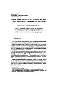
Design of a new aircraft is always a challenge, especially when unconventional configuration is considered. Unconventional configuration is usually the reason of many problems, however it could be very promising due to extraordinary characteristics - small drag, high performance, etc. The flying qualities are fundamental from pilot’s and potential customer’s point of view and have to be tested during conceptual stage of the project [1, 2]. The paper presents the stability and trim analysis of newly designed four-seat aircraft in three surface configuration (Fig.1). The small aircraft in presented unconventional configuration requires, that trim and stability are taken care of, due to very wide movement of gravity centre. The position of CG in presented aircraft changes from -20% to +20% of MAC. The whole payload is located in front part of fuselage (between main wing and canard). Canard plays an important role: to satisfy the longitudinal equilibrium. Therefore, it must be able to give sufficient lift force, especially in case of front CG position. From stability point of view, good characteristics of canard (big lift curve slope) are not desired. Because of that, it was a real challenge to satisfy trim and stability
in this range, in each case of payload. Paper presents the stability analysis of this three surface configuration, its influence to the final layout of the aircraft and remarks about flying qualities. 2
Aircraft presentation
The presented aircraft is designed as four-seats, twin-engine configuration. The main geometric, weight and performance (assumed) parameters are as follows: Wingspan Length Height Wing area Max. TO weight W/S Engines power Minimum airspeed Cruise airspeed (at sea level) Cruise airspeed (at 14000ft) Ceiling
11.0 m 9.0 m 3.0 m 12.5 m2 1280 kg 103 kg/m2 230 HP 90 km/h 280 km/h 320 km/h 18000 ft
The aircraft has slotted flaps on the main wing and plain flap on the canard. Flaps on the main wing and canard are coupled. The classical elevator on the horizontal tail is used for pitch control. 3
Methodology of analysis
The stability and trim analysis needs aerodynamic characteristics, including the stability and control derivatives. They were computed by use 1
T.GOETZENDORF-GRABOWSKI
Fig. 1 AT-6 three view - first version (courtesy AT-P AVIATION) A (1/4 MAC)
of the PANUKL [3] package, which is a low order potential solver. The trim and stability analysis was performed using SDSA [4, 5] similarly to tandem wing configuration presented in [6].
PZ
C.G.
My
3.1 Neutral point of stability Q
The neutral point of stability can be defined as the point which satisfies condition, that pitching moment coefficient is constant versus angle of attack or lift coefficient is constant: ∂Cm,N =0 ∂Cz
(1)
The equation of moment balance according to Fig.2 can be written as follows: ΣMCG = MY − PZ xCG
(2)
The equation 2 can be extended by aerodynamic forces to the following form: ΣMCG = 0.5ρSV 2CaCm,CG − 0.5ρSV 2Cz xCG (3)
XC.G.
Fig. 2 Main forces acting on the aircraft
Differentiating the equation 3 side by side and assuming that CG (centre of gravity) is located in the neutral point, we obtain: ∂CmN ∂Cm xN = − =0 ∂Cz ∂Cz Ca thus: x¯N =
∂Cm ∂Cz
(4)
(5)
The positive sign of x¯N denotes, that neutral point is located forward with respect to point of aerodynamic forces reduction. 2
STABILITY PROBLEMS
The computation of the pitching moment coefficient versus angle of attack was done using the panel method ([3]). The computational model is presented on Fig.3 and an example of the pressure distribution on Fig.4.
Fig. 5 Downwash distribution in horizontal tail area, angle of attack α = 5° It was estimated using sufficient reports [8]. The necessary downwash (Fig.5) characteristics were obtained from panel code [3].
Fig. 3 Computational model of AT-6 (first version) - mesh of 3609 panels [3]
Fig. 4 Pressure distribution, angle of attack α = 7.5°
Position of the neutral point of stability allows to compute the static margin, which is the distance from centre of gravity to neutral point, measured in percentage of MAC. This value is the basis for estimating the handling qualities of an aircraft. The static margin in case of free stick, is computed using the similar method. However it requires to compute moment coefficient in case when elevator is free. This in turn requires the calculation of free elevator deflection versus angle of attack. To compute such characteristics hinge moment coefficient of elevator is needed.
3.2
Dynamic stability
Second group of analysis, which must be done to estimate flying qualities of an aircraft, is the analysis of the dynamic of flight. It usually requires to solve an eigenvalue problem, and next to compute frequency and damping characteristics of each mode of aircraft motion. Such procedure needs complete aerodynamic characteristics including stability derivatives [5]. Most of stability derivatives were computed using PANUKL [3] package. Missing derivatives, especially derivatives with respect to vertical acceleration, were computed using hand-book methods and formulae [7]. The dynamic analysis was done using SDSA package, which is able to analyse linear and nonlinear model as well [5]. All results of dynamic stability analysis, including figures of merit, presented in this paper, were obtained from SDSA (Fig.6). 4
Results of analysis
The results of stability analysis presented in this chapter are divided into two groups. Fist part is related to static longitudinal stability. The second part concerns dynamic stability, especially lateral modes of motion. Finally, results of modified version of AT-6 are presented. 3
T.GOETZENDORF-GRABOWSKI
angle of main wing, is the reason why particular attention must be paid to the lateral stability.
Fig. 6 SDSA window - AT-6 flight simulation
4.1 Longitudinal static stability
Fig. 8 Dutch roll characteristics versus calibrated airspeed (CS-23.181 [9] criterion)
The static margin, which is a basic factor of longitudinal static stability, was computed for all configurations of CG position versus angle of attack and in consequence versus airspeed. The value of static margin in fixed and free stick cases is shown on Fig.7. It shows, that in case of rear position of CG, which corresponds with small payload (one light pilot) aircraft can be longitudinally unstable in case of free stick and for higher airspeed in case of fixed stick as well. The Fig.7 also shows a big difference between rear and front CG position. Fig. 9 Dutch roll characteristics against background of MIL-F-8785C [10] criteria
Fig. 7 Static margin versus airspeed
4.2 Lateral stability analysis - first stage The aircraft configuration, especially major part of fuselage in front of main wing and big dihedral
Fig. 10 Time to double for spiral mode against background of MIL-F-8785C [10] criteria
4
STABILITY PROBLEMS
Fig. 11 New configuration AT-6 meshes - main wing flaps deflected with: 15°(left), 30°(right).
The basic factor of directional static stability, i.e. derivative of yawing moment with respect to sideslip angle is positive, which means, that aircraft is statically stable. However, the dynamic analysis showed, that characteristics of the most important, from flying qualities point of view, lateral mode of motion, i.e. Dutch roll may not be satisfying and it can even be unstable for higher angle of attack. Fig.8 & 9 show Dutch roll characteristics against background of criteria defined by [9] and [10] accordingly. Both criteria are not satisfied for low value of airspeed, which corresponds with higher angle of attack. Second essential lateral mode of motion is spiral mode. This mode is stable in whole airspeed range, which is presented on Fig.10. 4.3 Handling qualities - final version The results of stability analysis of the first version of presented aircraft were not satisfying. Both longitudinal and lateral characteristics had to be improved. Longitudinal stability was improved by changing the internal layout of the aircraft and by rearranging of the weights breakdown. The lateral stability was improved by decreasing dihedral angle to zero and moving the main wing up, to perform the same position of engines. It improved Dutch roll and allowed to decrease the vertical tail area. New configuration was tested. Three aerodynamic configurations were considered: clean, take-off (flaps 15°), landing (flaps 30°) - Fig.11.
The aerodynamic characteristics were obtained using panel methods (Fig.12). All modes of motion were checked, taking into account requirements from airworthiness regulation for handling qualities.
Fig. 12 New configuration of AT-6 - example of pressure distribution, angle of attack α = −5°
4.3.1 Phugoid The dominating state variable in phugoid mode is the airspeed, and angle of attack is almost constant. The period is usually long and oscillations are well damped. The airworthiness requirements are not strong [9]: "Any long-period oscillation of the flight path (phugoid) must not be so unstable as to cause an unacceptable increase in pilot workload or otherwise endanger the aeroplane." (CS-23.181). The results obtained for AT-6 show (Fig.13), that phugoid is stable in the whole range of CG 5
T.GOETZENDORF-GRABOWSKI
position. Time needed to damp the amplitude to half is comparable with the period and varies between 40-60 s.
Fig. 14 Short Period oscillation - time to half damping versus calibrated airspeed Fig. 13 Phugoid - period and time to half damping versus calibrated airspeed
4.3.2 Short Period The short period oscillations connect rapid changes of angle of attack with pitch rate. The period is usually very short. The requirements according to CS-23.181 say [9]: "Any short period oscillation not including combined lateraldirectional oscillations occurring between the stalling speed and the maximum allowable speed appropriate to the configuration of the aeroplane must be heavily damped ...". The results of computation show, that short period oscillations are well damped (Fig.14), however for clean configuration in case of rear CG position, periodical character vanishes. Two non-periodical modes are stable. Strong damping characteristics, especially in case of front CG position, can cause pilot induced oscillations (PIO). The Fig.15 presents undamped natural frequency versus damping ratio against background of ESDU figure of merit (pilot rating). It shows, that PIO can occur.
Fig. 15 Short period figure of merit (ESDU) - undamped natural frequency versus damping ratio front CG position between the stalling speed and the maximum allowable speed appropriate to the configuration of the aeroplane must be damped to 1/10 amplitude in 7 cycles ...". The obtained results show (Fig.16), that all configurations satisfy airworthiness requirements. Fig. 17 presents Dutch roll characteristics against background MIL-F-8785-C figure of merit. It also shows good Dutch roll characteristics, which are in Level 1 & 2 for whole flight envelope. 4.3.4 Spiral mode
4.3.3 Dutch roll Dutch roll requirements according to CS-23.181 [9] are well defined: "Any combined lateraldirectional oscillations ("Dutch roll") occurring
After improvement of the previous version, spiral is the only mode, that is worse. However, airworthiness requirements are not strong - CS-23BOOK2: "... a slowacting mode called the spiral 6
STABILITY PROBLEMS
Fig. 16 Dutch roll characteristics versus calibrated airspeed (CS-23.181 [9] criterion)
Fig. 17 Dutch roll characteristics against background of MIL-F-8785C for landing configuration and rear CG position[10] criteria which may be stable, but is often neutrally stable or even mildly divergent in roll and yaw?". Similar requirements are in MIL-F-8785-C. Fig.18 shows spiral mode time to double, which shows, that spiral is unstable only for small values of airspeed and time to double is sufficiently big. 5 Concluding remarks The three surface configuration is a real challenge for a designer. It connects some potential advantages with possible problems. The canard allows to obtain additional lift surface and good stall characteristics. However, it decreases static margin. Canard together with classical horizontal tail surface cause very strong aerodynamic damping (big negative value of derivative of pitching moment with respect to pitch rate). So, for static
Fig. 18 Time to double for spiral mode against background of MIL-F-8785C for clean configuration, front CG position[10] criteria longitudinal stability, canard and classical horizontal tail are against and the collaborate to increase damping. Three surface configuration allows to locate the cabin (payload) in front of the main wing. It causes, that the aircraft is very sensitive on payload breakdown. Well designed main wing and canard can be almost sufficient to satisfy equilibrium. Then, horizontal tail is used mainly to control and doesn’t give strong negative lift as in classical configuration. References [1] Rizzi. A.: Modeling and simulating aircraft stability and control-The SimSAC project, Volume 47, Issue 8, November 2011, Pages 573-588 [2] Goetzendorf-Grabowski T.: Flight dynamic analysis of an aircraft within the conceptual stage of the aircraft design, Proceedings of the VIII RRDPAE conference, Brno 2008 [3] PANUKL potential solver, Software package, Warsaw University of Technology, http://www.meil.pw.edu.pl/add/ADD/Teaching/ Software/PANUKL [4] Goetzendorf-Grabowski T., Mieszalski D., Marcinkiewicz E., Stability analysis using SDSA tool, Progress in Aerospace Sciences, Volume 47, Issue 8, November 2011, Pages 636-646 [5] SDSA - Simulation and Dynamic Stability analysis, Software package, Warsaw University of Technology,
7
T.GOETZENDORF-GRABOWSKI
[6]
[7]
[8]
[9]
[10]
http://www.meil.pw.edu.pl/add/ADD/Teaching/ Software/SDSA Goetzendorf-Grabowski T., Figat M.: Aerodynamic and stability analysis of PPlane vehicle tandem-wing configuration, X Seminar on READ, Brno 2012 Goraj Z.: Flight dynamics models used in different national and international projects, Aircraft Engineering and Aerospace Technology: An International Journal, Volume 86, Number 3, 2014, Pages 166-178 Engineering Sciences Data Unit, Sub series Aerodynamics, 3A, Regent Street, London W1R 7AD, England (ESDU Data Sheets). European Aviation Safety Agency (2012) Certification Specifications for Normal, Utility, Aerobatic, and Commuter Category Aeroplanes - CS23, Amendment 3 MIL-F-8785C - Military Specification Flying Qualities of Piloted Airplanes, 5 November 1980.
Contact Author Email Address mailto:
[email protected] Copyright Statement The authors confirm that they, and/or their company or organization, hold copyright on all of the original material included in this paper. The authors also confirm that they have obtained permission, from the copyright holder of any third party material included in this paper, to publish it as part of their paper. The authors confirm that they give permission, or have obtained permission from the copyright holder of this paper, for the publication and distribution of this paper as part of the ICAS 2014 proceedings or as individual off-prints from the proceedings.
8