1
Stable Reconstruction of Irrotational Vector Fields based on the Discrete Longitudinal Ray Transform Alexandra Koulouri and Maria Petrou
Abstract In this paper, we show that the estimation of an irrotational vector field employing the longitudinal ray transform in the discrete domain is tractable, despite the fact that this problem cannot be solved in the continuous domain using the same formulation. We derive a set of algebraic equations and solve the ill conditioned inverse problem by directly inverting the produced ray projection matrix. In particular, we prove that the problem can be regularized via discretization and we provide an upper bound for the numerical error of the approximation, ensuring the stability of our formulation. We validate our theoretical results by performing simple simulations reconstructing irrotational fields based solely on boundary measurements without the need of any prior information (e.g. transversal integrals).
Index Terms Longitudinal ray transform, longitudinal line integral, ill conditioning, irrotational field.
I. I NTRODUCTION Vector field tomographic (VFT) methods are concerned with the reconstruction, and visualization, of a vector field in a bounded domain by measuring line integrals of projections of the vector field [32], [36]. In particular, they deal with the inverse problem of recovering a vector function from Department of Electrical and Electronic Engineering, Imperial College, London SW7 2BT, UK. E-Mail:
[email protected] Informatics & Telematics Institute, CERTH, Thessaloniki, GR-57001, Greece, and Department of Electrical and Electronic Engineering, Imperial College, London SW7 2BT, UK. E-Mail:
[email protected]
DRAFT
2
boundary measurements, i.e they solve a boundary value problem (BVP) formulated in integral terms [23]. As the majority of inverse problems, vector field tomography problems are ill posed in Hadamard’s sense [16], [14] and, therefore, further assumptions, measurements and constraints should be imposed for the full vector field recovery [23]. The theoretical foundation of VFT methods [23], [24], [3], [36], for the recovery of the unknown field in the continuous domain, is based on the Radon transform theory [22] and the Helmholtz decomposition theorem [20], [1] where a rapidly decreasing vector field (e.g. Schwartz vectorial functions [36]) can be decomposed into an irrotational and a solenoidal part. These methods employ the 2D Central slice theorem (CST) [22], and show that the Fourier transform of the longitudinal line integral of a 2D vector field is equal to the Fourier transform of the solenoidal part of this field [23], considering vanishing boundary values of the irrotational part. Hence, only the solenoidal part of a 2D field can be recovered while the irrotational part is eliminated using the Fourier Transform (FT) [23], [24]. The solenoidal field is estimated using classical methods of scalar tomography [22] based on either transformed oriented methods e.g. filtered back-projection [30], [24], [15] and Fourier methods [22], or algebraic methods [41], [13] e.g. algebraic reconstruction techniques (ART) [5]. Regarding the irrotational part, different methods have been proposed, using either integral based approaches [3], [15], [28] or partial differential equations (PDE) [23]. The integral based approaches proposed the estimation of sets of line integrals [15], [3] or Radon integrals [28] over projections of the field in different directions for the full recovery. In a 2D domain, the irrotational component ∫ of a field can be reconstructed using the transversal line integral L E · r⊥ dr with r⊥ being the unit vector normal to line L line integral [3], while both the longitudinal and transversal integrals can be used for the 3D reconstruction of a divergence-free field [15]. A more general approach for the full recovery of a 3D arbitrary field without making any prior assumption is described in [28], [25] using a different inner product formulation, the so-called Radon probe transform. However, in practice measuring the transversal line integrals or the general Radon probe transform is difficult and even impossible in some cases, e.g Doppler techniques [5] or the electrical potential estimation in geophysics [24]. Rather than using extra integral measurements, a PDE approach was proposed in [23] under
DRAFT
3
the assumption that there are no sources or sinks inside the bounded domain i.e. assuming the divergence-less property, and the values of the field at the boundaries are known. This is a classical boundary value problem (BVP) [1] which can be solved using known numerical techniques (finite difference methods [42], [2], finite elements methods [10], [38] or boundary elements methods (BEM) [35], [31]). However, for the general case where there is no knowledge concerning the sources inside the bounded domain and without making any further assumptions, the solution of this PDE problem is difficult, especially in practical problems like the inverse bioelectric field problem [11], [18]. So, the reconstruction of an irrotational field still remains a challenging task. The majority of the existing literature in Vector Field Tomography has been directed towards the imaging of fluid velocity fields from actively acquired measurements [23], [24], [34], [12], [3], [29], [17], [41], [33], [9]. In these problems, the fluid is assumed incompressible [23], [41] which in mathematical terms ensures the divergence-less property and usually there is no flux through the bounded domain, resulting to a solenoidal field that can be estimated following the well known FT based methods [30], [15]. In our work however, we are interested in applying similar methods for the recovery of an irrotational vector field as that is the case which arises in other application domains, most importantly for the inverse electroencephalography (EEG) problem [18]. We follow the idea of the algebraic methods [22], [26], [41] without applying any Fourier transformation to our data, and we use the discretized longitudinal ray transform for the reconstruction of an irrotational field from passively acquired boundary measurements. In particular, we show that the numerical solution of the linear system which arises from the discretization of longitudinal line integrals that trace a convex, discrete and bounded domain can give an accurate approximation of a smooth irrotational field. The main advantage of this approach is that there is no need to provide any prior information about the sources like in the PDE approach [11], [10], [38] while the differences of the values of the boundary measurements (EEG instant measurements) are equal to the longitudinal ray transform by definition. The paper is organized as follows. Section II presents briefly the mathematical and physical
DRAFT
4
properties of the vector field and describes the formulation of the discretized version of the problem. In Section III, we present a mathematical discussion on the ill-posedness of this inverse problem and the corresponding ill-conditioning of the produced numerical system and we explain how the ill conditioning is related with the properties of the vector field. In Section IV, we estimate the relative error of the solution and we show that this error is bounded in our discrete formulation. In Section V, we examine the stability of the produced linear system and the potential of our formulation to reconstruct a smooth irrotational field by performing simulations and in section VI, we include the conclusions and a brief discussion of future work. II. F ORMULATION OF THE INVERSE PROBLEM We assume that the field to be reconstructed is static, irrotational, and described by functions E on the Euclidean space E. Moreover, we consider that the field is restricted on a simply connected, convex region Ω, with piecewise boundaries ∂Ω where the field is not zero. As the field is considered irrotational, it satisfies ∇ × E = 0 and thus it can be expressed as the gradient of a scalar function Φ, i.e. E = −∇Φ [1] with Φ ̸= 0 on ∂Ω. The longitudinal line integral of E along a ray L with end points a and b ∈ ∂Ω is given by ∫
∫ E · dr =
IL = L
b
−∇Φ · dr = Φ(a) − Φ(b)
(1)
a
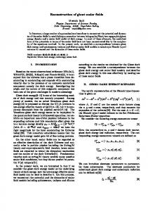
which will be the model equation of our problem and obviously is the longitudinal ray transform according to VTF methods [32]. In a 2D domain Ω, with E = (ex , ey ) and for a path defined by a ray with equation L(ϕ, ρ) : x cos ϕ + y sin ϕ = ρ (see fig. 1), the line integral IL depends on the values of ϕ and ρ of L defined at fig. 1. So, in our work we study the potential of the reconstruction of an irrotational field from line integrals of the form eq. 1 which trace a bounded and convex domain for all possible values of ϕ and ρ. In practice, as we have only a finite number of measurements u = {u1 , u2 , . . .} around the boundaries, the problem need to be considered in the discrete domain. Hence, following the concept of the algebraic methods [26], [41], [22], we reduce the longitudinal line integral to a linear system of equations for the estimation of the field at discrete points.
DRAFT
5
(s
in φ, -c os φ
)
y
=
rφ
ρ φ= in
xc
ys φ+ s o
φ
x
Fig. 1: Ray L on the (x, y) plane with parameters (ρ, ϕ) where 00 ≤ ϕ ≤ 3600 and ρ ∈ ℜ+ .
Thus, first the model equation (eq. 1) is converted to a numerically approximated integral (Quadrature rule [37]) IL = ∆u ≈
∑
wi Ei · ˆrϕ⊥
(2)
i
where Ei is the unknown vector value at discrete element i and wi the weights, corresponding to element i, determined by the applied interpolation scheme and ∆u are the boundary differences. All the line integrals yield a set of linear equations which is represented by ¯ b ≈ Ax
(3)
where x contains the unknown vector field components in a finite number of points and b is the column vector with the measured values of the integrals IL . The elements of the (transfer) ray ¯ represent the contribution to each IL of the projection of the unknown field projection matrix A components on each ray L. III. I LL POSEDNESS OF THE INVERSE PROBLEM The longitudinal and transversal ray transforms for vector fields (as for general tensor fields) are compact operators between appropriately defined L2 -spaces and, therefore, are not continuously invertible [22]. Thus, the inverse vector tomography problem is unstable and consequently illposed [7]. Generally speaking, the ill posedness technically applies only to continuous problems. The discrete version of an ill posed problem is ill conditioned and some kind of regularization is essential for a stable solution [8]. In practice, the line integral measurements are an incomplete sampling of information, mostly corrupted by noise which aggravates the ill conditioning of the DRAFT
6
formulated discretized inverse problem [22]. As we are going to show, the ill conditioning of the current problem besides of being the result of the numerical inversion of a compact operator (integral operator) and is aggravated by noise, it is also related both with the irrotational property of the reconstructed field and the modeling of the problem. In the following, we explain how the irrotational property affects the conditioning of the problem. We discuss about the stability of the discretized inverse problem and we show that the number of independent equations which stem from the problem’s discretized formulation give a final numerical system (eq. 3) which is not rank deficient.
A. Irrotational property and ill conditioning 1) Linear dependent equations: The irrotational property of the field implies that a line integral along a closed path is zero, thus, by connecting all pairs of boundary values, we obtain tracing lines (rays) which create closed paths (fig. 2). Therefore, when the tracing lines L1 , L2 , . . . form a closed curve, according to Stokes’ theorem [20] and the model equation (eq. 1) we obtain IL1 + IL2 + · · · + ILn = 0
(4)
Obviously, this indicates that a line integral ILk can be expressed as a linear combination of other longitudinal line integrals.
boundary values
Fig. 2: Tracing lines in the discrete domain which create closed-paths
One important task is the examination of the stability of the solution of the linear system (eq. 3), i.e. to check whether the independent equations are enough to give a unique solution, and whether DRAFT
7
¯ has full rank. matrix A Let us assume that we have a 2D square domain, a discrete version of which is a grid (a simple structured mesh) N × N and the unknown field components are 2N 2 . Our approach can be generalized to more general meshes for complex geometries of convex domains, however this is out of the scope of the current work. In particular, for a grid N × N (fig. 2), the number of the tracing rays are defined by pairs of boundary points with known value, which are placed at the boundary edges of all boundary cells (fig. 2). We exclude rays which connect pairs of points which belong to the same side of the square domain, as these rays do not lie inside the domain. For 4N points around the domain (N on each side), the connected pairs lead to m = 6N 2 model equations (eq. 1). So, as the number of unknown field components is n = 2N 2 , at first sight, we conclude that the linear system is over-determined ¯ being a rectangular matrix m × n. system (eq. 3), with A In order to define the number of independent equations, i.e equations which do not satisfy eq. 4, we have to exclude tracing lines which “close” paths (eq. 4), such as making sure that any line starting from one boundary point does not end up to the same boundary. In our 2D square domain with 4N points along the boundaries, the maximum number of tracing lines, while avoiding loops, is 4N − 1 and so, the number of independent line integrals is 4N − 1. The number of independent equations may be easily estimated using graph theory [6]. In particular, assume that the 4N points along the boundary of the square domain are the “vertices” of a graph G and that the lines which connect two points are the G graph’s “edges”. The main property that this graph should satisfy is that any two “vertices” are linked by a unique path, or, in other words, that the graph should be connected and without cycles. According to graph theory, a “tree” is an undirected simple graph G that satisfies the previous condition. A connected, undirected, acyclic graph with N “vertices” has N − 1 “edges”. Therefore, for 4N points, the system of equations may have at most 4N − 1 independent equations. Obviously, for a system with 2N 2 unknowns, the 4N − 1 independent equations lead to a rank deficient system [19]. 2) Discussion on the produced linear system and the domain resolution: The linear dependencies are quite significant in the continuous domain. On the contrary, in the discrete domain, where the continous integral ( model equation eq. 1) is approximated by a finite sum (eq. 2), the dependencies
DRAFT
8
are not so obvious, as the accuracy of the continuous domain is lacking. Thus, taking approximated integrals (eq. 2), leads to sums of equations which is not equal to zero. So, with the discretization of the bounded domain, the linear dependencies of the equations are eliminated and consequently ¯ (eq. 3) is not rank deficient. the ray projection matrix A If the accuracy improves, i.e rather than applying “rough” approximation, a more accurate interpolation scheme is applied and the resolution of the domain improves, the dependencies become ¯ (eq. 3) approximates a rank-deficient matrix more obvious. As a result, the ray projection matrix A i.e. there are nearly linearly dependent lines and the linear system may be severely ill conditioned. In particular, for a N × N square grid, with 4N boundary points and 2N 2 unknowns, when spatial resolution N → ∞, the number of independent equations F (N ) converges to 4N − 1 and the number of independent equations cannot exceed the number of unknowns as limN →∞ limN →∞
4N −1 2N 2
F (N ) 2N 2
=
= 0, and the system becomes rank deficient.
Next, we prove that the formulation of the problem in the discrete domain acts as a regularization of the ill conditioning caused by the intrinsic irrotational property of the field [27], [21]. Mathematically, this fact is verified by estimating the error between the exact and the estimated solutions and proving that this error is bounded in the discrete domain while tends to be unbounded when the resolution increases. IV. R EGULARIZATION OF THE DISCRETIZED
PROBLEM
A. Relative error of the solution The theoretical examination of the stability and the ill conditioning of the discrete inverse problem is based on the estimation of the relative error between the exact and the estimated field at the discrete points of the domain. As we are working in the discrete domain, model equation (eq. 1) is converted to a finite sum given by IL =
∑
ai E[i]ˆrϕ⊥ + δ E˜
(5)
i
where ai is the length of the path of the ray through element i of the discrete domain and δ E˜ is the remainder or discretization error (see Appendix A). The aggregate of this equation for a finite
DRAFT
9
number of measurements b = {I1 , I2 , . . . , Im } produces the algebraic equations given by ˜ b = Ax + δ E
(6)
˜ = [δ E˜1 , . . . , δ E˜m ]T is a column vector with the discretization error and x has the exact where δ E values of the field at the center of each element i of the domain (Appendix B). The theoretical relative error (RE) between the exact vector values x and the least squares solution ¯ † b of the linear system for the general case, where ray projection matrices are rectangular, xLS = A is
†
¯ ∥x − xLS ∥ ¯ † ∥2 ∥A∥2 + eA k(A) + eb ∥A ∥2 ∥b∥ ≤ e A ∥A ∥x∥ ∥x∥
(7)
where k(A) = ∥A∥2 ∥A† ∥2 is the condition number and ∥A∥2 is the Euclidean norm of A such as ∥A∥2 = max∥x∥=1 ∥Ax∥ = σmax with σmax , the maximum singular value of A, and ∥A† ∥2 =
1 σmin
with σmin the minimum singular value of A [19]. Constant eb is the discretization error coefficient ˜ = eb ∥b∥. When eb → 0, the spatial resolution improves. Constant ea is the interpolation with ∥δ E∥ ¯ = A − δA and δA is the column error coefficient, which is defined by ∥A∥ = ea ∥δA∥ where A vector of the interpolation error. If there are not interpolation errors, i.e. the weight wi of eq. 2 is ¯ = A (Appendix B). Further details for equal to the length of the ray through element i, then A the mathematical proof of this error (RE) are given in Appendix C. From eq. 7 we deduce that the accuracy of the solution depends simultaneously on the interpolation and discretization coefficients eA and eb respectively, as well as on the condition number of matrix A.
B. Conditions for bounded solution error A bounded relative solution error (RE) (eq. 7) is ensured when the discretization error coefficient is non zero, i.e. 0 < eb ≪ 1. Hence, the discretization process is used as a kind of “selfregularization” of the problem. In order to examine the effect of the discretization to error’s bound,
DRAFT
10
we assume eA → 0. Thus, the relative error (RE) (eq. 7) becomes ∥x − xLS ∥ eb ∥A† ∥2 ∥b∥ ≤ ∥x∥ ∥x∥ eb ≤ ∥A† ∥2 ∥A∥2 1 − eb eb = k(A) 1 − eb
(8)
According to eq. 8, for a bounded RE we need to prove that the condition number k(A) < ∞. In effect, we have to show that the ray projection matrix of the system (eq. 3) is not rank deficient which means that the number of linearly independent rows is greater than the unknown field’s components. In particular, when 0 < eb ≪ 1, the computed equations (eq. 2) are an approximation of the model equation (eq. 1 or eq. 5). That means that the summation of any set of these equations cannot be zero in any closed path and there is no equation that can be expressed as a linear combination ¯ (eq. 3) has full of the others (eq. 4 is not satisfied), as we discussed in section III. So, matrix A rank and the condition number is not infinity. Then, the relative error (RE) (eq. 8) ∥x − xLS ∥ eb ≤ k(A) < ∞ ∥x∥ 1 − eb
(9)
is bounded. If the resolution of the discrete domain improves such as the discretization error eb → 0, then the equations approximate the continuous line integrals (eq. 1) and our linear system (eq. 3) becomes rank deficient, since the number of the independent equations is always less than the unknowns (section III-A2). Consequently, the condition number k(A) → ∞ and the RE bound converges to infinity. So, a non-zero discretization error ensures a finite upper bound to the relative solution error (RE) and thus the ill conditioning (i.e. instability) of this inverse problem derived from the intrinsic irrotational property of the reconstructed field can be regularized. Moreover, we mention that an extreme coarse discretization of the domain increases again the ill conditioning of the problem as ˜ is essential when eb → 1, the RE is again unbounded. Therefore, a bounded discretization error δ E
DRAFT
11
for an accurate solution to balance the solution approximation error and the ill conditioning of the linear system. The proper choice of the discretization parameter for the problem’s regularization is an important issue which needs further theoretical examination and we leave it as a future work. V. R ESULTS In this section, we verify the theoretical approach discussed in the previous sections, and we assess the accuracy with which the numerical solution approximates the true one. The mathematical and geometric properties of the model are defined in subsection V-A, while in subsections V-B and V-C, the evaluation of the previous theoretical findings is performed.
A. Simulation Setup In the current tests, we recover vector fields in a 2D square bounded domain Ω. The discretization of the domain is described as Ω : {(x, y) ∈ [−U, U ]2 }
→ |{z}
{[i, j] ∈ [1 : N, 1 : N ]}
(10)
Discretization
where i =
⌊ x+U ⌋ P
,j =
⌊ y+U ⌋ P
(nearest neighbor approximation) with [P × P ] the cell’s size and
N = 2U/P the spatial resolution of the discrete domain. The numerical representation of the longitudinal line integrals (model equations) which trace the domain are given by IL ≈
∑
Nij E[i, j] · (sin ϕ, − cos ϕ)∆r
(11)
where Nij is the number of samples in cell [i, j] of the domain with ∆r being the sampling step along the ray and ∆r ≪ P . Thus, we obtain the system of equations (eq. 3). We solve the system using well known numerical methods. (We tested both QR Factorization and Householder Transformations and we obtained the same results [37].) In the next subsections we perform simulations such as to examine the following scenarios: •
¯ and verify the theoretical relationship between condition number of ray projection matrix A resolution;
•
test how the spatial resolution of the discrete domain affect the relative solution error for different fields (smooth and non-smooth); DRAFT
12
•
examine the effect of noisy measurements on the recovered field.
The goal is to examine experimentally the ill conditioning of the system for different source distributions (close and far from the bounded domain) and the relationship between the spatial resolution of the domain and the ill conditioning, as well as the effect of noise on the final solution. ¯ of For the examination of the ill conditioning, the singular values of ray projection matrix A the linear system (eq. 3) are estimated performing the singular value decomposition (SVD) of ¯ A slowly decreasing singular value spectrum with a broader range of nonzero singular values A. indicates a better conditioning, while a spectrum rapidly decreasing to zero shows increase of the ill conditioning. A second indicator that is used, is the condition number as a gauge of the transfer ¯ and vector b (eq. 3) to the solution vector x [19]. error from matrix A
B. Condition number and resolution The curve in fig. 3 presents the relationship between the grid resolution and the condition number of the ray projection matrix. 1100
1000
900
Condition Number
800
700
600
500
400
300
200
100
5
10
15
20
25
30
35
Resolution NxN
Fig. 3: Condition number for increasing values of grid resolution N × N .
As in theory, when the resolution improves, the condition number becomes greater. Hence, the higher condition number implies that the solution of the linear system is more sensitive and unstable ¯ or b perturbations. to A Instability of the system means that the continuous dependence of the solution upon the input data cannot be guaranteed and in the presence of input noise (perturbations) the system’s “behavior” is unpredictable. If there was no additional noise or other external sources of error, the ill conditioning DRAFT
13
¯ being of order of the system (intrinsic ill conditioning), due to the high condition number k(A) 10m , has an effect on the computed solution, in the sense that a loss of m digits’ accuracy in the solution is induced (rule of thumb [19]). Thus, for instance, for a floating point arithmetic of 16 digits, only 16 − m digit solution accuracy can be achieved. So, in the absence of sources of noise, there is mainly a loss in accuracy when the condition number is high, while there is no great effect on the system’s stability. Different discretization levels of the grid impact the conditioning of the linear system (fig.3). The increase in spatial resolution e.i. when discretization error tends to zero, the ill conditioning of the inverse problem aggravates. Similarly, in fig. 4, grid refinement results to faster descent of the
Res=10 Res=14 Res=17 Res=20 Res=24 Res=30 Res=35
1
10
0
Singular Values
10
-1
10
0
0.1
0.2
0.3
0.4
0.5
0.6
0.7
0.8
0.9
1
Normalized Singular Value Index
Fig. 4: Spectrum of the singular values for different levels of the grid resolution.
singular values of the spectrum to zero and to a narrower range of non zero singular values, which ¯ and the stability of the linear system deteriorate. also indicates that the conditioning of matrix A
C. Experimental estimation of the relative solution error In this section, we perform two sets of reconstruction experiments. In the first set, we run simulations for the approximate reconstruction of two irrotational fields, one smooth and one not so smooth, such as to generally assess the potential of the numerical approach. In the second set of experiments, we evaluate our method using electrostatic fields in a 2D square domain, produced by electric monopoles Qi (obeying Coulomb’s law [20]). According to the preconditions, the electrostatic field is a good example for the validation of the method as it is static and irrotational.
DRAFT
14
In most of the simulations, the point sources are positioned outside the bounded domain in order to avoid singularities, since in practical problems the value of a field cannot be infinite. 1) Initial evaluation: In these tests, we evaluate our theoretical results by reconstructing two theoretical fields E1 and E2 . In particular, we estimate the relative solution error of the fields and we examine how this error is influenced by the resolution when there is no noise in the measurements. Field E1 (fig. 5a) is quite a smooth field while field E2 (fig. 6a) includes vortices at points (x = a, y = b). Field E2 is irrotational in any simply connected region, excluding points (x = a, y = b). Hence, in our experiments, we exclude points (x = a, y = b). These points are not far from the region of reconstruction, as we want to examine the reconstruction effectiveness for a slightly distorted fields. Our results (table I) show that for low spatial resolution, the relative error is higher for field E2 (fig. 6a) which is slightly distorted than for smoother field E1 (fig. 5a). For poor spatial resolution, only low spatial frequency terms can be captured. Therefore, a smooth field can be efficiently recovered by only a few frequency terms while a field with singularities cannot. Thus, the relative error of distorted field E2 is higher. However, as the resolution improves, more frequency components can be recovered and the relative error of E2 progressively decreases (table I). In subsection V-B, we show that even though the error decreases with the grid refinement, the conditioning of the linear system deteriorates. In particular, for resolution 10 × 10, the condition ¯ is k(A) ¯ ≃ 110 while for 20 × 20, k(A) ¯ ≃ 600. In the absence of noise, the number of matrix A higher condition number affects only the accuracy of the solution e.g. when resolution is 20 × 20, ¯ → 103 , then, there is a loss of 3 digits in the accuracy. Numerically this loss has not a great k(A) impact on the solution for floating point measurements [19] and this loss in accuracy is balanced for dense grid (higher sampling rate) so that the solution error is reduced.
E1 E2
REmagnitude REorientation REmagnitude REorientation
10 0.08 0.02 0.148 0.044
15 0.08 0.015 0.08 0.0267
Resolution 20 25 30 0.08 0.073 0.07 0.0096 0.011 0.0049 0.07 0.067 0.06 0.02 0.0185 0.0167
TABLE I: Relative errors (RE) of the magnitude and the orientation between the true and the reconstructed fields.
DRAFT
15 1
1
0.8
0.8
0.6
0.6
0.4
0.4
0.2
0.2
0
0
−0.2
−0.2
−0.4
−0.4
−0.6
−0.6
−0.8
−0.8
−1 −1
−0.5
0
0.5
−1 −1
1
−0.5
Reconstructed Field
(a)
measurements are given by Φ1 (x, y) = −e
2 +y 2
−x
2
1
1 0.8
0.6
0.6
0.4
0.4
0.2
0.2
0
0
−0.2
−0.2
−0.4
−0.4
−0.6
−0.6
−0.8
−0.8
0
Reconstructed Field
(a)
1
0.5
1
x2 +y 2 2
, −y −
x2 +y 2 2
) where boundary
such as E1 = −∇Φ1 .
0.8
−0.5
0.5
(b)
Fig. 5: (a)Reconstructed and (b) True field E1 (x, y) = 12 (−xe−
−1 −1
0
Real Field
−1 −1
−0.5
0
0.5
1
Real Field
(b)
∑ ∑ 2 2 Fig. 6: (a)Reconstructed and (b) True field E∑ 2 (x, y) = (− i (x − i (y − bi )/[(x − ai ) + (y − bi ) ], ai )/[(x−ai )2 +(y−bi )2 )] with Φ2 (x, y) = − i tan−1 (y−bi /x−ai ) for i = 2 and (a1 , b1 ) = (0, 1.4), (a2 , b2 ) = (0, −1.4)
2) Electrostatic fields: Similar results with those of the previous irrotational fields we can extract for the following electrostatic fields. In the first simulations, the sources are selected to be far from the recovery domain such as the field to be smooth. For a bounded domain Ω : {(x, y) ∈ [−U, U ]2 ⊂ ℜ2 } = [−1, 1]2 and two point sources with the same charge, placed at (−19, −19) and (19, 19) on the (x, y) coordinate system, and small sampling step ∆r = 10−4 P (eq.11) along the integral line, we obtain the errors given in table II. The recovered field is depicted in fig. 7 for different levels of resolution. Obviously, as the resolution increases, the relative errors decrease as more spatial frequency terms of the field can be recovered (table II). For point sources closer to the region of interest, e.g. two point sources are at (1.2, 1.2) and DRAFT
16
Resolution REmagnitude REorientation
10 0.09 0.25
15 0.07 0.17
20 25 0.058 0.051 0.14 0.11
TABLE II: Relative errors (RE) of the magnitude and the orientation between the true and the reconstructed smooth electrostatic field. 1
1
1
0.8
0.8
0.8
0.6
0.6
0.6
0.4
0.4
0.4
0.2
0.2
0.2
0
0
0
−0.2
−0.2
−0.2
−0.4
−0.4
−0.4
−0.6
−0.6
−0.6
−0.8
−0.8
−0.8
−1 −1
−0.5
0
0.5
1
−1 −1
−0.5
0
0.5
1
−1 −1
−0.5
0
Reconstructed Field
Reconstructed Field
Reconstructed Field
(a)
(b)
(c)
0.5
1
Fig. 7: Reconstructed smooth field for grid resolution (a) 10 × 10, (b) 15 × 15 and (c) 20 × 20. 1
1
1
0.8
0.8
0.8
0.6
0.6
0.6
0.4
0.4
0.4
0.2
0.2
0.2
0
0
0
−0.2
−0.2
−0.2
−0.4
−0.4
−0.4
−0.6
−0.6
−0.6
−0.8
−0.8
−0.8
−1 −1
−0.5
0
0.5
1
−1 −1
−0.5
0
Real Field
Real Field
(a)
(b)
0.5
1
−1 −1
−0.5
0
0.5
1
Real Field
(c)
Fig. 8: True smooth field for grid resolution (a) 10 × 10, (b) 15 × 15 and (c) 20 × 20.
(−1.2, −1.2) on the (x, y) plane (fig. 10), the relative errors REmagnitude and REorientation (table III) are higher compared with the errors of the smooth field (table II). Clearly, the relative errors increase as the field sources are placed closer to the recovery domain, due to the rapid change of the field inside the domain, which is not captured fully by the sampling rate used. 3) Electrostatic field with singularities: Fig. 11a shows the result of the reconstructed field, for the case where the sources are localized inside the bounded domain. The relative error of the magnitude of the field is high. However, the error of the orientation is acceptable (REorientation =0.3 DRAFT
17
Resolution REmagnitude REorientation
10 0.27 0.41
15 0.19 0.4
20 25 0.18 0.178 0.4 0.4
30 0.17 0.311
TABLE III: Relative errors (RE) of the magnitude and the orientation between the true and the reconstructed rapidly decay field. 1
1
1
0.8
0.8
0.8
0.6
0.6
0.6
0.4
0.4
0.4
0.2
0.2
0.2
0
0
0
−0.2
−0.2
−0.2
−0.4
−0.4
−0.4
−0.6
−0.6
−0.6
−0.8
−0.8
−0.8
−1 −1
−0.5
0
0.5
1
−1 −1
−0.5
Reconstructed Field
0
0.5
1
−1 −1
−0.5
Reconstructed Field
0
0.5
1
Reconstructed Field
(a)
(c)
Fig. 9: Reconstructed rapidly decaying field for grid resolution (a) 10 × 10, (b) 15 × 15 and (c) 20 × 20. 1
1
1
0.8
0.8
0.8
0.6
0.6
0.6
0.4
0.4
0.4
0.2
0.2
0.2
0
0
0
−0.2
−0.2
−0.2
−0.4
−0.4
−0.4
−0.6
−0.6
−0.6
−0.8
−0.8
−0.8
−1 −1
−0.5
0
Real Field
(a)
0.5
1
−1 −1
−0.5
0
Real Field
0.5
1
−1 −1
−0.5
0
0.5
1
Real Field
(b)
Fig. 10: True rapidly decaying field for grid resolution (a) 10 × 10, (b) 15 × 15 and (c) 20 × 20.
in fig. 11a and REorientation = 0.4 in fig. 11b) and the vector arrows point correctly to the sources’ locations (fig. 11a). The field close to the sources is not smooth, i.e. the true field has both high and low spatial frequency components and, thus, for poor spatial resolution (fig. 11a, fig. 11b), only the low spatial frequency components can be recovered as in the previous case (fig. 10) when the point sources were placed closer to the grid. Even though the error is high due to resolution limitations, the recovered field points correctly to the source locations, which indicates that the low
DRAFT
18
spatial frequency terms give some extremely useful information about the direction of the field.
0.5
0.5
0.4
0.4
0.3
0.3
0.2
0.2
0.1
0.1
0
0
−0.1
−0.1
−0.2
−0.2
−0.3
−0.3
−0.4
−0.4
−0.5 −0.5
0
−0.5 −0.5
0.5
Reconstructed Field
0
0.5
Reconstructed Field
(a)
(b)
Fig. 11: Recovered field when a) two point sources and b) four point sources are inside the bounded domain (not in the center of cells).
The presence of singularities in the field implies the presence of higher frequency terms in the spectrum of the field, which in turn imply the necessity for denser sampling of the reconstruction domain. However, the need for higher spatial resolution leads to high condition numbers of the linear system. So, there is an open question concerning the optimal choice of the discrete grid such as to obtain an accurate result while preserving stability of the system.
D. The effect of additive noise Finally, we examine the stability of our system for the case where there is additive noise in measurements b (eq. 3). The noise corrupted boundary measurements of a smooth field are produced by 2 point sources positioned at (−19, −19) and (19, 19) far from the bounded domain. For our evaluation, we use the relative magnitude of the input and output error to provide a measure of stability factor S: eout =
∥x − xLS ∥ ∥x∥
ein =
¯ − b∥ ∥b ∥b∥
S=
eout ein
(12)
¯ = b + n randn(), where randn() is the Matlab Noisy measurements are created according to b function which produces pseudo-random numbers whose elements are normally distributed and n ∈ DRAFT
19
[mean(b)10−3 , mean(b)10−2 ]. We estimate the mean value of eout using 100 different noise vectors for each value n. The Signal to Noise ratio (SNR) of the inputs, given by 20log10 (1/ein−mean (n)), is measured along the horizontal axis, in fig. 12a and fig. 12b. For the case where SNR is high i.e. for low additive noise, the output error is low, especially when the level of resolution is better, as a more accurate recovery of the field can be achieved. On the contrary, for lower SNR, the output error is slightly better when the level of the resolution is low, as the “coarse” discretization leads to more stable linear system. This is also indicated by S factor. 180 0.5 160
Res=10x10\CondN=116 Res=13x13\CondN=240 Res=16x16\CondN=371 Res=18x18\CondN=579
0.45
Res=10x10\CondN=116 Res=13x13\CondN=240 Res=16x16\CondN=371 Res=18x18\CondN=579
140
0.4 120
S factor
eout
0.35
0.3
100
80
0.25 60 0.2 40 0.15 20 0.1 30
35
40
45
50
55
SNRin=20log10(1/ein
)
mean
60
65
0
30
35
40
45
50
SNRin=20log10(1/ein
(a)
55
60
)
mean
(b)
Fig. 12: a) Mean values of output error eout and b) Stability factor S for different levels of input SNR and different levels of resolution.
In particular, from the curves of fig. 12b, we deduce that the linear system is more stable when both the level of resolution the level of noise are low. Moreover, comparing the curves of fig. 12a, we conclude that the accuracy of the output solution deteriorates with the additive noise and at high noise situations, the accuracy becomes even worse for better resolution. So, in the present of noise when, we intent to reconstruct more complex fields and thus a better resolution is needed such as to capture all field’s components, further regularization, should be considered and possibly some kind of pre-processing of the measurements to reduce the input noise [8]. VI. D ISCUSSION AND CONCLUSIONS This study explored the feasibility of the reconstruction of an irrotational field in a bounded domain when a finite number of boundary measurements is known. In particular, following the DRAFT
20
concept of the algebraic methods [22], we formulated the problem in the discrete domain and we solved a numerical system of equations derived from the discretized longitudinal line integrals which trace the field’s domain and are equal to the differences of the boundary values. Thus, we achieved to approximate an irrotational field at a finite number of points. We discussed the effect of the irrotational property of the field on the stability of the numerical system and the fact that we cannot extract a solution in the continuous domain using this formulation. We showed that the linear system tends to become rank deficient and the problem becomes severely ill conditioned as the resolution of the discrete domain increases. We proved that the error of the solution is bounded for the discrete case while tends to be unbounded when the spatial resolution improves. Hence, we concluded to the fact that the discretization can be an efficient way of regularizing this ill posed continuous problem and, therefore, the problem is tractable in the discrete domain. Our simulations indicated that this approach gives satisfactory results, particulary at low noise situations. We showed that different discretization choices of the grid impact the formulation of the linear system and that the increase in spatial resolution actually increases the condition number and consequently the ill-conditioned nature of this inverse problem. In this work, we presented only a few examples of fields with singularities. The proper choice of the discretization parameters for singular fields seems to be extremely essential to derive a satisfactory solution and thus further regularization has to be considered. There are only a few VFT publications which examine fields singularities [4]. Future work should address the problem of vector field tomographic reconstruction of irrotational fields with singularities as well as the theoretical development of the necessary discretization constraints to optimize the conditioning of the problem while minimizing the approximation error.
Acknowledgements This work is supported by John S. Latsis Public Benefit Foundation of Greece (www.latsisfoundation.org).
DRAFT
21
A PPENDIX A T HE LONGITUDINAL RAY TRANSFORM
IN THE DISCRETE DOMAIN
The definite integral model equation (eq. 1) can be converted to a finite sum given by [37], IL =
∑
∥∆Lm ∥E[m]ˆrϕ⊥ + δ E˜
(13)
m
where ∥∆Lm ∥ is the length of the path of the ray (line) through element m of the discrete domain, E[m] is the value of the field at this element and δ E˜ is the remainder or discretization error. Following simple mathematical steps we show how eq. 13 is deduced by eq.1. In particular, eq. 1 employing Riemmann’s integral formulation is given by IL =
lim
∑
max{∆rk }→0
Ek · ˆrϕ⊥ ∆rk
(14)
k
where Ek are the samples along ray L with step ∆rk and ˆrϕ⊥ the unit vector in the direction of line L. The numerical treatment of the problem is based on the assignment to each Ek a value E[m] according to an interpolation scheme. So, each sample Ek is the sum of E[m] plus an error vector δEk i.e. Ek = E[m] + δEk
(15)
For a convenient form of our final result, we may consider that ∆rk 7→ 0 and approximately constant such as ∆rk = ∆r and Nm ∈ ℵ the number of samples Ek ∈ in ∆Lm of element m, then the line integral of element m is I∆Lm = lim
∆r→0
∑
Ek ˆrϕ⊥ ∆r = lim
Ek ∈∆Lm
( = lim
∆r→0
∆r→0
Nm E[m] +
∑
)
∑
(E[m] + δEk )ˆrϕ⊥ ∆r
Ek ∈∆Lm
(16)
δEk ˆrϕ⊥ ∆r
k
˜ The error vector caused by the discretization in an element [m] is δ E[m] =
∑ k
δEk . So, the line
DRAFT
22
integral (eq. 14) can be represented as the sum of I∆Lm terms, e.i. IL =
∑
I∆Lm = lim
∆r→0
m
(
lim
∑
∆r→0
∑( ) ˜ ˆrϕ⊥ ∆r = Nm E[m] + δ E[m] m
)
Nm ∆rE[m]ˆrϕ⊥
(17) + δ E˜
m
where δ E˜ is the discretization error term given by δ E˜ = lim∆r→0
∑ m
˜ ˆrϕ ∆r. δ E[m] ⊥
The product Nm ∆r (eq. 17) represents the length of path of the ray which “corresponds” to element [m]. As shown in fig. ??, the finite number of samples along the line segment with constant and finite step ∆r cause a difference between the real length of ∆Lm and Nm ∆r. Particularly, we have that Nm ∆r = ∥∆Lm ∥ − εm ∆r, with |εm | < 1 being an error coefficient. Therefore, the line integral (eq. 17) is written as ( ) ∑ IL = lim (∥∆Lm ∥ − εm ∆r)E[m]ˆrϕ⊥ + δ E˜ ∆r→0
=
∑
m
(18)
∥∆Lm ∥E[m]ˆrϕ⊥ + δ E˜
m
which is eq. 13. A PPENDIX B C ALCULATING ERROR OF THE DISCRETIZED PROBLEM ¯ (eq. 3) where the equations are given by In practice, we estimate the solution of b ≈ Ax IL ≈
∑
wm E[m] · ˆrϕ⊥
(19)
i
Comparing eq. 19 with eq. 18 we have that weight wm can be expressed as wm = ∥∆Lm ∥ − εm ∆r ¯ = A − δA with δA being the column vector of the weighting error. and hence A A PPENDIX C N UMERICAL ERROR OF THE SOLUTION We present the proof of the relative error of the solution between the estimated values given by ¯ and the exact values x when Ax = b + δE for the general case where A and A ¯ are xLS = Ab rectangular, derived using Wedin [39] analysis. DRAFT
23
Theorem 1. The relative error (RE) between the least square solution xLS of minimum norm defined ¯ † b and the system Ax + δ E ˜ = b is given by by A †
¯ ∥x − xLS ∥ ¯ † ∥2 ∥A∥2 + eA k(A) + eb ∥A ∥2 ∥b∥ ≤ e A ∥A ∥x∥ ∥x∥
(20)
¯ ∈ ℜp×l with p > l, A ¯ = A − δA, ∥δA∥2 = eA ∥A∥2 ̸= 0 and ∥δ E∥ ˜ = eb ∥b∥ = where A and A ̸ 0 with ¯ ≥ Rank(A) = v ≤ p. Here symbol † indicates the pseudo-inverse of a matrix. Rank(A) ¯† For the estimation of the relative error (RE) we employ the decomposition theorem A† − A discussed in [39] and [40]. As we deal with rectangular matrices, we employ the decomposition theorem [39], ¯ † ¯ † = −A ¯ † (A − A)A ¯ †−A ¯ † (I − AA† ) + (I − A ¯ † A)A A† − A
(21)
¯ = b − δ E, ˜ Therefore, if b ¯ †b ¯−A x − xLS = A† b ¯ † (b ¯−A ¯ + δ E) ˜ = A† b ¯ † )b ¯ †δE ¯−A ˜ = (A − A ] [ ¯ † b ¯ †δE ¯ † (A − A)A ¯ †−A ¯ † (I − AA† ) + (I − A ¯ † A)A ¯−A ˜ = −A †
(22)
¯ = 0 as b ¯ ∈ Range(A) (i.e. b ¯ = Ax). (I − AA† )b So, eq. 22 becomes x − xLS
[ ] † †¯ † † ¯ ¯ ¯ ¯ ¯ †δE ˜ = −A (A − A)A + (I − A A)A b − A ¯ † δAx + (I − A ¯ † A)x ¯ −A ¯ †δE ˜ = −A
(23)
According to the matrix norm inequalities of 2-norm ∥.∥2 [19] for matrices B and C ∈ ℜm×n ∥BC∥2 ≤ ∥B∥2 ∥C∥2 and ∥B + C∥2 ≤ ∥B∥2 + ∥C∥2 and ∥Bx∥2 ≤ ∥B∥2 ∥x∥ when x is a vector ∈ ℜn×1 . So, ¯ † δAx + (I − A ¯ † A)x ¯ −A ¯ † δ E∥ ˜ 2 ∥x − xLS ∥ ∥ − A = ∥x∥ ∥x∥ † ¯ δAx∥2 + ∥(I − A ¯ † A)x∥ ¯ 2 + ∥A ¯ † δ E∥ ˜ 2 ∥−A ≤ ∥x∥
(24)
DRAFT
24
¯ † A)x∥ ¯ 2 may be written as: Wedin [39] analysis shows that term ∥(I − A ¯ † A)x| ¯ 2 = ∥(I − A ¯ † A)A ¯ T (A† )T x∥2 ∥(I − A
(25)
¯ = AT (A† )T A† b ¯ = AT (A† )T x due to Moore Penrose pseudo-inverse identities Since, x = A† b A† = A† AA† = (A† A)T A† = AT (A† )T A† [19]. ¯ + δA)T then this term (eq. 25) becomes If we set AT = (A T ¯ † A)( ¯ A ¯ + δA)T (A† )T x∥2 = ∥(I − A ¯ † A)δA ¯ ∥(I − A (A† )T x∥2
(26)
¯ † A) ¯ A ¯ T = 0 (Moore Penrose identity A ¯T = A ¯ †A ¯A ¯ T [19]). As (I − A Therefore, RE (eq.7) is given by T ¯ † δAx∥2 + ∥(I − A ¯ † A)δA ¯ ¯ † δ E∥ ˜ 2 ∥x − xLS ∥ ∥−A (A† )T x∥2 + ∥A ≤ ∥x∥ ∥x∥ ¯ † ∥2 ∥δ E∥ ˜ ∥A T ¯ † ∥2 + ∥(I − A ¯ † A)δA ¯ ≤ ∥δA∥2 ∥A ∥2 ∥A† ∥2 + ∥x∥ † ¯ ˜ ¯ † ∥2 + ∥δA∥2 ∥A† ∥2 + ∥A ∥2 ∥δ E∥ ≤ ∥δA∥2 ∥A ∥x∥
(27)
T ¯ ¯ † A)δA ∥2 ≤ ∥δAT ∥2 . as ∥(I − A
˜ = eb ∥b∥ and k(A) = ∥A† ∥2 ∥A∥2 , we obtain: If we set ∥δA∥2 = eA ∥A∥2 , ∥δ E∥ ¯ † ∥2 ∥b∥ ∥x − x¯LS ∥ e b ∥A † ¯ ≤ eA ∥A ∥2 ∥A∥2 + eA k(A) + ∥x∥ ∥x∥
(28)
R EFERENCES [1] G. B. Arfken and H. J. Weber, Mathematical methods for physicists, 6th ed., Elsevier Academic Press, 2005. [2] M. A. Bezuglova, E. Y. Derevtsov, and S. B. Sorokin, The reconstruction of a vector field by finite difference methods, J. Inv. Ill-Posed Prob 10 (2002), no. 2, 123–154. [3] H. Braun and A. Hauck, Tomographic reconstruction of vector fields, Signal Processing, IEEE Transactions on 39 (1991), no. 2, 46–471. [4] E. Derevtsov and V. Pickalov, Reconstruction of vector fields and their singularities from ray transforms, Numerical Analysis and Applications, no. 1, 21–35. [5] L. Desbat and A. Wernsdorfer, Direct algebraic reconstruction and optimal sampling in vector field tomography, Signal Processing, IEEE Transactions on 43 (1995), no. 8, 1798 –1808. DRAFT
25
[6] R. Diestel, Graph theory, Springer Verlag New York-Electronic Edition 2000, 1997. [7] J. Hadamard, Lectures on cauchy’s problem in linear partial differential equations, Dover Publications, 1923,New York. [8] Per Christian Hansen, Rank–deficient and discrete ill–posed problems: Numerical aspects of linear inversion, 1998. [9] I. Javanovic, Inverse problems in acoustic tomography: Theory and applications, Ph.D. thesis, EPFL, 2008. [10] C. R. Johnson, Computational and numerical methods for bioelectric field problems, Critical Reviews in BioMedical Engineering, CRC Press, Boca Ratan, 1997, pp. 162–180. [11] C. R. Johnson, R. S. MacLeod, and M. A. Matheson, Computational medicine: Bioelectric field problems, Computer 26 (1993), 59–67. [12] S. A. Johnson, J. F. Greenleaf, W.A. Samayoa, F.A. Duck, and J. Sjostrand, Reconstruction of three-dimensional velocity fields and other parameters by acoustic ray tracing, 1975 Ultrasonics Symposium, 1975, pp. 46–51. [13] I. Jovanovia, L. Sbaiz, and M. Vetterli, Acoustic tomography for scalar and vector fields: Theory and application to temperature and wind estimation, Journal of Atmospheric and Oceanic Technology (2009). [14] A. Kirsch, An introduction to the mathematical theory of inverse problems, Springer-Verlag New York., NY, USA, 1996. [15] S. J. Lade, D. Paganin, and M. J. Morgan, 3-D Vector tomography of Doppler-transformed fields by filtered-backprojection, Optics Communications 253 (2005), no. 4-6, 382–391. [16] M. M. Lavrentiev, A. V. Avdeev, and V. I. Priimenko, Inverse problems of mathematical physics, Walter De Gruyter, Sep 2003. [17] L. Lovstakken, S. Bjaerum, D. Martens, and H. Torp, Blood flow imaging - a new real-time, flow imaging technique, IEEE Transactions on Ultrasonics, Ferroelectrics and Frequency Control 53 (2006), no. 2, 289–299. [18] J. Malmivuo and R. Plonsey, Bioelectromagnetism : Principles and Applications of Bioelectric and Biomagnetic Fields, 1st ed., Oxford University Press, USA, 1995. [19] C. D. Meyer, Matrix analysis and applied linear algebra, 2000. [20] P. M. Morse and H. Feshbach, Methods of theoretical physics, York: McGraw-Hill, 1953. [21] F. Natterer, Error bounds for tikhonov regularization in hilbert scales, Applicable Analysis 18 (1984), 29–37. [22]
, The mathematics of computerized tomography, Society for Industrial and Applied Mathematics, Philadelphia, PA, USA, 2001.
[23] S. J. Norton, Tomographic reconstruction of 2D vector fields: Application to flow imaging, Geophysical Journal International 97 (1988), no. 1, 161 – 168. [24]
, Unique tomographic reconstruction of vector fields using boundary data, Image Processing, IEEE Transactions on 1 (1992), no. 3, 406–412.
[25] N. F. Osman and J. L. Prince, Reconstruction of vector fields in bounded domain vector tomography, Image Processing, 1997. Proceedings., International Conference on, vol. 1, 1997, pp. 476–479. [26] M. Petrou and A. Giannakidis, Full tomographic reconstruction of 2D vector fields using discrete integral data, The Computer Journal 53 (2010), no. 7, doi: 10.1093/comjnl/bxq058. [27] R. Plato and G. Vainikko, On the regularization of projection methods for solving iii-posed problems, Numerische Mathematik 57 (1990), 63–79. [28] J. L. Prince, Tomographic reconstruction of 3D vector fields using inner product probes, IEEE transactions on image processing 3 (1994), 216–219.
DRAFT
26
[29] D. Rouseff, K. B. Winters, and T. E. Ewart, Reconstruction of oceanic microstructure by tomography: A numerical feasibility study, J. Geophys. Res. (1991), no. 96:C5, p. 8823–8833. [30] T. Schuster, The 3d doppler transform: elementary properties and computation of reconstruction kernels, Inverse Problems 16, no. 3, 701. [31]
, Defect correction in vector field tomography: detecting the potential part of a field using bem and implementation of the method., Inverse Problems 21 (2005), no. 1, 75–91.
[32]
, 20 years of imaging in vector field tomography: A review, In Mathematical Methods in Biomedical Imaging and Intensity-Modulated Radiation Therapy (IMRT) (A. K. Louis (Eds.) Y. Censor, M. Jiang, ed.), Series: Publications of the Scuola Normale Superiore, CRM Series, vol. 7, Birkhuser, 2008.
[33] T. Schuster, D. Theis, and A. K. Louis, A reconstruction approach for imaging in 3D cone beam vector field tomography, Journal of Biomedical Imaging 2008 (2008), 1–17. [34] A. Schwarz, Three dimensional reconstruction of temperature and velocity fields in a furnace, Particle and Particle Systems Characterization 12 (1995), no. 2, 75–80. [35] G. Shou, L. Xia, M. Jiang, F. Liu, and S. Crozier, Forward and inverse solutions of electrocardiography problem using an adaptive bem method, Proceedings of the 4th international conference on Functional imaging and modeling of the heart, FIMH’07, 2007. [36] Gunnar Sparr and Kent Strhln, Vector field tomography, an overview, 1998. [37] Heath M. T., Scientific computing : An introductory survey, 1 Nov 2001. [38] D. F. Wang, R. M. Kirby, and C. R. Johnson, Resolution strategies for the finite-element-based solution of the ecg inverse problem, IEEE Transactions on Biomedical Engineering, vol. 57, 2010, pp. 220–237. [39] P. Wedin, Perturbation theory for pseudo-inverses, BIT Numerical Mathematics 13 (1973), 217–232. [40] M. Wei, The perturbation of consistent least squares problems, Linear Algebra and its Applications 112 (1989), 231 – 245. [41] A. Wernsdorfer, Complete reconstruction of three–dimensional vector fields, Karlsruhe, 1993, pp. 132–135. [42] D. G. Zill and Cullen M. R., Differential equations with boundary–value problems, 4th ed., Thomson Brooks/Cole, 1997.
DRAFT