descriptions. Keywords: Mass Customization, Knowledge-based Con- .... sometimes make the meaning of STEP concepts unclear. [23]. Other standards for the ...
IEEE TRANSACTIONS ON ENGINEERING MANAGEMENT, IEEE, TO APPEAR 2007.
31
Standardized Configuration Knowledge Representations as Technological Foundation for Mass Customization Alexander Felfernig, Computer Science and Manufacturing, University Klagenfurt
Abstract— The effective integration of configuration system development with industrial software development is crucial for a successful implementation of a Mass Customization strategy. On the one hand, configuration knowledge bases must be easy to develop and maintain due to continuously changing product assortments. On the other hand, flexible integrations into existing enterprise applications, e-marketplaces and different facets of supply chain settings must be supported. This paper shows how the Model Driven Architecture (MDA) as an industrial framework for model development and interchange can serve as a foundation for standardized configuration knowledge representation, thus enabling knowledge sharing in heterogeneous environments. Using UML/OCL as standard configuration knowledge representation languages, the representation of configuration domain-specific modeling concepts within MDA is shown and a formal semantics for these concepts is provided which allows a common understanding and interpretation of configuration task descriptions. Keywords: Mass Customization, Knowledge-based Configuration, Standardized Knowledge Representations.
I. I NTRODUCTION In today’s rapidly changing and globalizing markets the traditional Mass Production paradigm appears anachronistic. Highly competitive markets are redefining the way companies do business. In this context, Mass Customization [1], [2] appeared as a new paradigm representing the trend towards the production of highly variant products under Mass Production time and pricing conditions. Key enablers for implementing a Mass Customization strategy are, on the one hand, intelligent manufacturing systems which allow the provision of customer-individual products on the basis of flexible
production processes [1], [3], [4], on the other hand, systems supporting the management of highly variant products and services [5], [6], [7], [8]. Focusing on the second aspect, configuration systems (configurators) support the design of customizable products following a building blocks principle where basic parts can be configured into different sets of assemblies. Essential gains [9], [10], [11], [12] provided by configurators are, for example, an increased level of sales force knowledge, pre-informed customers (Web-based configurators), a reduction of sales force training costs, explicit knowledge about products formalized in an organizational memory, less routine work, reduced response times through automated check of customer requirements and reduced delivery times by avoiding errors in the quotation and order processing phase. Although configurators have shown their applicability in various real-world applications [9], [11], [12], [13], [14], [15] there exist additional requirements related to the integration of configuration technologies into industrial software processes which must be fulfilled in order to improve the applicability and increase the acceptance of configurators. Standardized Interfaces. Each configuration environment has its own (proprietary) knowledge representation language. This makes the application and integration of such technologies demanding for software development departments. Efforts are triggered by the development and maintenance of specific interfaces to the configuration system [10], for example, for the export of configuration results to an underlying ERP system or the import of user profiles from a CRM system with the goal to support personalized configuration processes for the customer [16]. As reported in [10], integration tasks can
32
IEEE TRANSACTIONS ON ENGINEERING MANAGEMENT, IEEE, TO APPEAR 2007.
become too difficult with the result that purchased configuration software has to be exchanged for an alternative configurator. Reduced Development and Maintenance Efforts. The development of configuration knowledge bases is conducted in cooperation between technical experts and domain experts. The development of such knowledge bases can be very expensive [10]. In this context, the application of industrial standard representations can ease knowledge base development and maintenance processes since those representations are known by technical experts and in many cases also known by domain experts without a technical background. In this context, a major requirement for the applicability of standard representations is a graphical modeling environment which makes those representations accessible to domain experts as well [17]. Increased Customer Acceptance. With the goal to reduce software development and maintenance costs, information system departments focus on standardization and interoperability. In this context, configuration systems are required to provide standard knowledge representation formats. Such formats contribute to an improved flexibility of a company’s software infrastructure. For our customers in the financial services domain, standardized interfaces are a major decision criterion for incorporating a configurator into the existing software environment. Reusable Configuration Knowledge. Resources required to develop and maintain configuration knowledge bases are substantial, see, e.g., [10], [11]. The implementation of configuration knowledge bases is an iterative development, maintenance and validation process. In most cases the resulting knowledge base is encoded in the proprietary language of the underlying configuration system. This makes related investments extremely vulnerable due to the fact that, for example, changing requirements on the configurator application could lead to the need of having to change the whole configuration environment [10]. In this case no support is available for transforming a knowledge base into the representation of the new environment. Standardized Knowledge Representations. Dozens of competing (and partially incompatible) B2B frameworks
supporting the representation of non-configurable products exist, for example, RosettaNet, cXML or BizTalk [18], [19]. These standards do not provide mechanisms for the representation of configurable products and services [20]. STEP applications [21], [22] as industrial standards for the representation of configurable products are restricted to specific types of products (e.g., products in the automotive industry). They are very large and hardly provide real examples for product models which sometimes make the meaning of STEP concepts unclear [23]. Other standards for the representation of configurable products are restricted in their expressiveness w.r.t. the underlying constraint representation, e.g., BMEcat [20]. Therefore, standard representations are required which provide easy to use modeling concepts and the expressivity for designing configurable products as well as product catalogs. This paper shows how UML/OCL [24], [25], [26] as Software Engineering modeling languages can be applied to configuration knowledge design and thus, contribute to an improved applicability of configuration technologies. The major contributions of this paper are the following: •
•
•
•
The representation of configurable products and services is shown using UML/OCL as standard knowledge representation languages. The paper provides a formal basis for UML/OCL modeling concepts. This formalization supports a clear and common understanding of configuration task definitions. The paper shows the integration of UML/OCL based configuration models into the Model Driven Architecture (MDA) [27], [28], [29] which supports model-based system interoperability. Finally, experiences from applying UML/OCL in industrial projects are reported.
The remainder of the paper is organized as follows: Section II gives an introduction to knowledge-based configuration, the Model-Driven Architecture (MDA) and UML/OCL as MDA-related knowledge representation languages. Section III provides a formal semantics for the modeling concepts of UML/OCL and shows the representation of typical configuration domain-specific
STANDARDIZED CONFIGURATION KNOWLEDGE REPRESENTATIONS AS FOUNDATION FOR MASS CUSTOMIZATION
types of constraints, using UML/OCL. Section IV shows the integration of UML/OCL into MDA. Section V presents our configuration knowledge base development environment. Finally, Section VI presents experiences related to the application of standard configuration knowledge representations in industrial settings. II. BACKGROUND Knowledge-based Configuration. Knowledge-based configuration has a long history as an application area of Artificial Intelligence, see, for example, [9], [11], [12], [13], [14], [15]. Informally, configuration can be seen as a special case of design activity [30], where the artifact being configured is assembled from instances of a fixed set of well-defined component types which can be composed conforming to a set of constraints. Such constraints represent technical restrictions, restrictions related to economic factors and restrictions according to production processes (see, e.g., Fig. 3). The result of a configuration process is a concrete product configuration, i.e., a list of instances and (if needed) connections between those instances. Examples for product configurations are descriptions of concrete computers to be delivered (see, e.g., Fig. 4) or portfolio offers consisting of financial services fitting to the wishes and financial restrictions of a customer (e.g., a concrete combination of loan and corresponding risk insurance). Industry demonstrates high demand for configuration systems. Examples of applications are, e.g., the automotive industry [13], the telecommunication industry [11], the computer industry [9], [31] or power electric transformers [12]. Starting with rule-based systems such as R1/XCON [9], model-based knowledge representations (in contrast to rule-based representations) have been developed which strictly separate domain knowledge from problemsolving knowledge. Such a clear separation significantly increases the effectiveness of configuration application development and maintenance [11], [13], [14], [32] since changes in the domain knowledge do not effect search strategies and vice versa. Core configuration, i.e., guiding the user and checking the consistency of user requirements with the knowledge base, solution presentation and translation of configuration results into detailed bill-
33
of-materials are major tasks to be supported by a configurator [33]. Configuration knowledge bases are generally built using proprietary languages (see, e.g., [14], [34], [35]). In most cases knowledge bases are developed by technical experts who elicit product, marketing and sales knowledge from domain experts. Configuration knowledge bases consist of a formal description of the product structure and additional constraints restricting the possible combinations of different components of the product structure. Configurators are considered as toolkits for open innovation, i.e., tools supporting customers in the product identification phase [33], where customers are innovators articulating their (potentially) new requirements leading to new innovative product solutions [33], [36]. Mass Confusion [37] which denotes the overwhelming of customers by a large number of possible solution alternatives (choices), is a phenomenon which often comes with the application of configurators. This motivated the development of personalized configuration applications taking into account a customer’s knowledge, wishes and needs [16].
Model Driven Architecture. The Model Driven Architecture (MDA) [27], [28], [29] is the result of standardization efforts of the Object Management Group (OMG www.omg.org). The focus of MDA is the provision of an integrated architecture supporting system interoperability on the application level based on the sharing of metadata. The overall strategy for sharing and understanding metadata consists of the automated development, publishing, and management of models [29]. The long-term vision for MDA includes applications capable of automatic discovering capabilities/properties of other applications. MDA can be defined as the implementation of model engineering principles around a set of OMG standards like the Unified Modeling Language (UML) [24], [25] and the Object Constraint Language (OCL) [26]. UML/OCL are the most frequently applied modeling languages within the context of the MDA.
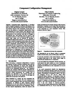
An MDA-based process is related to the development of models on different abstraction layers [38] (see
34
IEEE TRANSACTIONS ON ENGINEERING MANAGEMENT, IEEE, TO APPEAR 2007.
different facets of distributed problem-solving scenarios [16], [40]. In this case configuration models are published (exchanged) in order to provide external applications with an access to the provided set of configurable products [16]. Fig. 1. Different abstraction levels of the Model Driven Architecture (MDA).
Fig. 1). First, a Platform Independent Model (PIM)1 is designed on an implementation-independent abstraction level (specification of the functionality). UML/OCL models on this level are the basis for knowledge interchange between different platforms. Second, a PIM is extended with platform-specific properties which results in a Platform Specific Model (PSM). PSMs specify how a particular functionality is implemented. Finally, a PSM is translated into the source code representation of the underlying platform. Fig. 2 sketches the model-driven (MDA-based) integration of configuration environments based on the exchange of product catalogs and configuration models (on the PIM level).
Fig. 2. MDA-based application integration of product catalogs, configurators and electronic marketplaces.
Such an architecture supports different application scenarios ranging from the interchange of product catalogs [20] (e.g., suppliers publish their products in a marketplace environment) and knowledge sharing [39] to the interchange of knowledge bases as the basis for 1
A platform is defined as a set of technologies that provide a coherent set of functionality through interfaces and specified usage patterns [28].
UML Configuration Models. UML is widely applied as modeling approach in industrial software development projects. For presentation purposes a simplified UML configuration model (class diagram) of a personal computer (Computer) is introduced as a working example (see Fig. 3). This model represents the generic product structure, i.e., all possible variants of a Computer. The set of possible products is restricted by a set of OCL constraints which are related to technical restrictions, economic factors and restrictions according to the production process. The modeling concepts provided in UML are a basis for the design of a configuration knowledge base. Such a knowledge base is modeled using classes/attributes (e.g., HDUnit/capacity), associations (e.g., a motherboard (MB) is part of a Computer), multiplicities which refine the definition of associations (e.g., a Computer consists of at least one motherboard (MB) and at most two motherboards), and generalization hierarchies (e.g., a CPU can be a CPU1 or a CPU2). The set of possible configurations is restricted by additional constraints (e.g., an IDEUnit requires a motherboard of type MB1) which are represented as OCL invariants.2 OCL Constraints. Constraints are defined using OCL invariants which are expressed in the context of a certain class (Fig. 3 includes three technical constraints defined in the context of the class Computer). Note that OCL itself does not provide language elements which support the definition of classes, attributes, and relationships, i.e., the structural model must be defined within a UML class diagram. The relationship between a UML class diagram and OCL constraints is specified by assigning constraints to a certain context class (in the simple configuration model of Fig. 3 all OCL constraints are assigned to the context class Computer). Class attributes in the UML configuration model can be accessed in 2
Constraints are based on OCL 2.0 [26], the term OCL constraint is used synonymously with the term OCL invariant (OCL expression of type Boolean).
STANDARDIZED CONFIGURATION KNOWLEDGE REPRESENTATIONS AS FOUNDATION FOR MASS CUSTOMIZATION
35
Fig. 3. Example model of a configurable computer defined as UML class diagram (product structure) with a set of corresponding OCL constraints.
an OCL expression using the ’.’ operator. A typical OCL constraint imposed on a configurable Computer could state that an IDEUnit requires the inclusion of a motherboard of type MB1 (see constraint c1 in Fig. 3). OCL constraints are typically built of the following language elements3: •
•
•
Context: a context describes for which classes the constraint has to hold, e.g., the constraint c1 has to hold for all instances of the class Computer. Navigation expression: evaluating the expression self.HDUnit results in a set of HDUnit instances associated with an instance of the class Computer. If there exists an association between two classes in a class diagram, a navigation step between those classes can be defined in OCL. The result of such an expression is a set of instances (objects) or a single object. Navigations can be defined over a sequence of classes, e.g., self.MB.CPU is a legal navigation expression resulting in a set of CPU instances which are connected to a Computer instance. Finally, navigation expressions can be defined on attributes, for example, the result of self.MB.CPU.clockrate is a set of corresponding CPU clockrate values. Collection operation: the select operation (a specific collection operation) calculates a subset of the in-
3 An overview of the supported modeling concepts can be found in [41].
•
•
voking set consisting of elements fulfilling the subexpression. In constraint c1 of Fig. 3 HDUnits of type IDEUnit are selected, where self.HDUnit is the invoking set and select(oclIsTypeOf (IDEUnit)) is the select expression.4 Operation size: operates on sets resulting in the number of elements in the set. In constraint c1 of Fig. 3 the number of IDEUnit instances part of a Computer instance is returned. Logical operator implies: operates on logical expressions. In constraint c1 the existence of an IDEUnit instance in the final configuration requires (implies) the existence of a corresponding motherboard of type MB1.
Instances. After having defined the model of a configurable product, the configuration system can start to calculate concrete configurations (configuration solutions). The customer can articulate his/her requirements on a solution. Assuming that the requirements in the example are include a text-editor (Textedit) and two IDEUnits, the configuration system calculates a solution represented by a number of instances (objects) and their connections. Such a configuration result is depicted in Fig. 4 where, e.g., ideunit-1 is an instance of the class IDEUnit. 4 Note that self is the starting instance of an OCL constraint, i.e., in our example an instance of the class Computer.
36
IEEE TRANSACTIONS ON ENGINEERING MANAGEMENT, IEEE, TO APPEAR 2007.
TABLE I D OMAIN D ESCRIPTION (DD).
Group
Values {computer, software, dtpsoftware,
CLASSES
textedit, hdunit, ideunit, scsiunit, mb, mb1, mb2, cpu, cpu1, cpu2, screen}.
Fig. 4.
Configuration result as UML instance diagram.
attributes(software)={capacity}. attributes(hdunit)={capacity}. ATTRIBUTES
III. F ORMAL S EMANTICS FOR UML/OCL- BASED C ONFIGURATION M ODELS Configuration knowledge interchange requires a clear and common understanding of the problem definition and its solution. Therefore it is necessary to agree on the definition of a configuration task and its solution. This section provides a formal definition of a configuration task which is the basis for many existing configuration systems, e.g., [11], [14], [35]. The following definition is based on a consistency-based approach [42] where a configuration task can be seen as a logical theory which describes a class library5 , a set of constraints, and customer requirements. Classes are described by attributes and relationships to other classes. The result of a configuration task is a set of instances, their attribute values, and connections that all together satisfy the logical theory. The form of the logical sentences used to represent the logical theory is restricted to a subset of range-restricted first-order-logic with set extension.6 Following this approach, a configuration task is defined as follows. Definition 1 (Configuration Task): In general, a configuration task is described by two sets of logical sentences (DD, SRS). DD represents the domain description of the configurable product, i.e., the product structure and additional constraints on the allowed combinations of instances and attribute settings. SRS (system requirements specification) specifies the particular system requirements (e.g., customer requirements) defining an individual configuration task instance. DD includes the 5 Note that the term class is used synonymously with the term component type which is also frequently used in the configuration domain [15]. 6 Every variable of the consequence part of the clause is also contained in the antecedent part.
attributes(cpu) = {clockrate}. /* further attribute definitions for subtypes */ roles(software) = {software-of-computer}. roles(hdunit) = {hdunit-of-computer}. roles(mb) = {mb-of-computer, mb-of-cpu}. roles(cpu) = {cpu-of-mb}.
ROLES
roles(screen) = {screen-of-computer}. roles(computer) = {computer-of-software, computer-of-hdunit, computer-of-mb, computer-of-screen}. /* further role definitions for subtypes */ dom(software, capacity) = {50..100}. dom(hdunit, capacity) = {10000..20000}.
DOMAINS
dom(cpu, clockrate) = {300..500}. /* further domain definitions for subtypes */
description of the classes, roles of classes in relations and attributes with their domains (dom). In Table I the structural part of the domain description (DD) of the Computer configuration model is depicted (CLASSES, ATTRIBUTES, DOMAINS and ROLES). Additional logical sentences are added to DD representing constraints on the product structure (e.g., constraints on the type of generalization hierarchy, on the multiplicities of roles, or on the compatibility of different instance types in the configuration result). The derivation of such constraints from a UML/OCL configuration model is sketched in the following subsections.
STANDARDIZED CONFIGURATION KNOWLEDGE REPRESENTATIONS AS FOUNDATION FOR MASS CUSTOMIZATION
TABLE II S YSTEM R EQUIREMENTS S PECIFICATION (SRS).
Group
TABLE III C ONFIGURATION R ESULT.
Group
Values type(ideunit-1, ideunit).
type(textedit-1, textedit).
type(ideunit-2, ideunit).}
type(ideunit-1, ideunit). INSTANCES
{conn(computer-1, computer-of-hdunit, CONNS
type(mb1-1, mb1).
conn(computer-1, computer-of-hdunit,
type(cpu1-1, cpu1). type(screen-1, screen).} {conn(computer-1, computer-of-software,
{val(ideunit-1, capacity, 10000).
textedit-1, software-of-computer).
val(ideunit-2, capacity, 10000).} CONNS
The second input for a configuration task is SRS which represents additional requirements related to a configuration result. SRS is specified by a number of key instances which must be part of the result. The requirement two IDEUnits must be included in the configuration is shown in Table II. Additional requirements as well as configuration results are described using the literals type/2, conn/4, val/3 which are included in the following sets: •
•
•
type(ideunit-2, ideunit).
ideunit-1, hdunit-of-computer).
ideunit-2, hdunit-of-computer).} ATTRS
Values {type(computer-1, computer).
{type(computer-1, computer). INSTANCES
INSTANCES: is a set of literals of the form type(c,t), where the constant c represents an instance of a class t and t is included in the set CLASSES. CONNS: is a set of literals of the form conn(c1,r1,c2,r2), where c1, c2 are connected instances and r1, r2 are the connecting ROLES. ATTRS: is a set of literals of the form val(c,a,v), where c is an instance, a is an attribute of c and v is the attribute value.
Using the sets INSTANCES, CONNS and ATTRS, the configuration result depicted in Fig. 4 can be represented as follows (see Table III). Note that this result is consistent with the domain description (DD) of Table I and the customer requirements (SRS) of Table II. Based on the above definition of a configuration task, a configuration result (consistent configuration) can be defined as follows. Definition 2 (Consistent Configuration): If (DD, SRS) is a configuration task and INSTANCES, CONNS, ATTRS represent a configuration result, then the configuration result is consistent iff DD ∪ SRS ∪
37
conn(computer-1, computer-of-hdunit, ideunit-1, hdunit-of-computer). conn(computer-1, computer-of-hdunit, ideunit-2, hdunit-of-computer). ...}. {val(textedit-1, capacity, 100).
ATTRS
val(ideunit-1, capacity, 10000). val(ideunit-2, capacity, 10000). val(cpu1-1, clockrate, 300). ...}
INSTANCES ∪ CONNS ∪ ATTRS is satisfiable. Table I sketches the logical representation (DD) of UML product structures. In the following subsections the inclusion of further constraints into the domain description (DD) is shown. The corresponding logical sentences additionally restrict the set of possible configurations, i.e., the set of possible instance models which correspond to a UML/OCL configuration model. Formalizing OCL Constraints. Since UML is a widespread modeling language, OCL itself has established an important role in the field of formal specification languages. However, the definition of the OCL semantics is based on a proposed syntax and additional textual descriptions and examples. Although this is a quite intuitive approach for demonstration purposes, a corresponding formal definition is needed. In the following it is shown how OCL constraints (OCL invariants, i.e., expressions of type Boolean) can be translated into the logic-based representation of a domain description (DD).7 Each OCL constraint is translated into a corresponding logical sentence S following an implication schema where the left7
For reasons of space limitations the translation is discussed in the context of examples. The complete set of translation rules can be found in [41].
38
IEEE TRANSACTIONS ON ENGINEERING MANAGEMENT, IEEE, TO APPEAR 2007.
TABLE IV T RANSLATION OF OCL C ONSTRAINT C 1 (F IGURE 3).
OCL expression
Logical representation
(a) context Computer inv:
type(ID1 , Computer) ∧ ResultSet1 ={ID1 }
(b) (self.HDUnit
connected_set(↓ResultSet1 , HDUnit, ↑ResultSet2 )
(c) ->select(oclIsTypeOf(IDEUnit))
selected_set1 (↓ResultSet2 , ↑ResultSet3 )
(d) ->size > 0) implies
|ResultSet3 |=Val1
(e) (self.MB
connected_set(↓ResultSet1 , MB, ↑ResultSet4 )
(f) ->select(oclIsTypeOf(MB1))
selected_set2 (↓ResultSet4 , ↑ResultSet5 )
(g) ->size > 0)
|ResultSet5 |=Val2 ⇒ ¬Val1 > 0 ∨ Val2 > 0.
connected_set(↓Setin , C, ) ⇐ ID ∈ Setin ∧ type(Resultout , C) ∧ conn(ID,_,Resultout ,_). selected_set1 (↓Setin , ) ⇐ Resultout ∈ Setin ∧ type(Resultout , IDEUnit). selected_set2 (↓Setin , ) ⇐ Resultout ∈ Setin ∧ type(Resultout , MB1).
hand side (LHS) contains variables which correspond to the result of evaluations of navigation expressions and the right-hand side (RHS) contains the corresponding logical consequence. In order to assure a consistent naming of variables in S, each variable has a corresponding index which is unique inside S. The following variable types are generated into S.
expression is one object if the multiplicities of the related classes along the path of the navigation expression are [0..1] or [1..1]. The result of a navigation expression is a set of objects in all other cases. In the example of Table IV (b), the result of the navigation expression self.HDUnit is a set of objects since the multiplicity of HDUnits associated to Computers is specified with [2..6].
ID: variables used for representing instances within S, e.g., ID1 in Table IV (a) represents a Computer instance. ResultSet: variables used for representing a set of instances or basic values inside S, e.g., ResultSet2 in Table IV (b) represents the set of HDUnits connected to ID1 . Val: variables used for representing a basic value (e.g., integer) within S, e.g., Val1 in Table IV (d) stores the number of HDUnit instances of type IDEUnit.
In the logical theory (DD), the result of a navigation expression is represented by a set identifier (ResultSet). Navigations are expressed by the predicate connected_set/3 which implements one step to another class and connected_set_a/3 which implements the navigation to a class attribute. Selection operations such as in Table IV (c) are calculating subsets of instances of a given set. For the representation of selection operations on the logical level a predicate selected_set/2 is introduced which implements the criteria defined as parameter of the select operator (the index of selected_set/2 is unique within the given domain description DD).8 Finally, the size operation is translated into a cardinality and the relational operator is directly translated into DD, see Table IV (d), (g). The entries (e) and (f) are handled analogously to the entries (b) and (c) in Table IV.
•
•
•
Each OCL constraint is defined within the context of a class. Starting from this reference point, attributes of the class can be accessed and navigation expressions over associations can be defined. The translation of OCL context specifications is shown in Table IV (a), where ID1 as an instance of the class Computer is the starting point for navigations in the configuration model. OCL navigation expressions can be formulated using the access operator ’.’. The result of such a navigation
8
For the definition of the predicates connected_set(_a)/3 and selected_set/2 an LDL-like [43] syntax is applied. After calling, e.g., the predicate connected_set(↓ResultSet1 , HDUnit, ↑ResultSet2 ), ↑ResultSet2 (output) contains all HDUnits which are connected with Computer instances of ↓ResultSet1 (input).
STANDARDIZED CONFIGURATION KNOWLEDGE REPRESENTATIONS AS FOUNDATION FOR MASS CUSTOMIZATION
39
A. Multiplicities and Generalization Hierarchies
C. Incompatibility constraints
The formalization of multiplicities and generalization hierarchies is shown in Table V, where additional logical sentences are introduced to DD representing the partof relationship between Computer and HDUnit and the generalization between the motherboards MB, MB1 and MB2.
Certain types of instances must not be part of the same final configuration, they are incompatible. The pattern for OCL incompatibility constraints on the class level (both an instance of class A and an instance of class B must not be part of the same configuration result) as well as on the attribute level (both an instance of class A with attribute value v=a and an instance of class B with attribute value v=b must not be part of the same configuration result) is shown in Table IX (b). An example for an OCL incompatibility constraint is shown in Table VII expressing that an SCSIUnit instance and an MB1 instance must not occur in a configuration result together.
There exists a set of constraint types which are frequently used when building configuration models. These constraint types and their representation in OCL are discussed in the following subsections.
B. Requirement constraints In some cases, the existence of an instance of a specific class requires the existence of another specific instance in the configuration result. Using OCL, such requirement constraints can be expressed on the class level (an instance of class A part of the configuration result requires an instance of class B to be part of the configuration result) as well as on the attribute level (an instance of class A with attribute value v=a requires an instance of class B with attribute value v=b to be part of the configuration result). The pattern for OCL requirement constraints on the class level is shown in Table IX (a), where the expressions Aij denote the jth class in the navigation path to class Ci . Also the pattern for OCL requirement constraints on the attribute level is shown in Table IX (a). In cases, where a subclass S of C within a generalization hierarchy is accessed via a navigation path, the expression C->select(oclIsTypeOf (S)) must be added to the navigation path. This selection is used in the following examples. An example for a requirement constraint is shown in Table VI which expresses that, if an instance of an IDEUnit is part of the configuration result, an MB1 instance must be contained as well. Note that the constraint types of Table IX refer to situations where 0..n associations are concerned (constraints on class level) and 0..1 associations are concerned (constraints on attribute level).9 9 Hybrid variants are possible - for readability reasons those variants are omitted.
D. Resource constraints Parts of a configuration task can be seen as a resource balancing task where some of the classes produce some resources and others are consumers (e.g., the harddisk capacity needed by the installed software must not exceed the provided hard-disk capacity). Using OCL, resource constraints can be expressed as follows assuming that {Ci , ..., Ck } denotes a set of consumers and {Cl , ..., Cn } denotes a set of producers and {aip , ..., akq }, {alr , ..., ans } denote the resource attributes of those classes. The pattern for OCL resource constraints is shown in Table IX (c). An example for a resource constraint is the following (see Table VIII).10 Resource constraints can be represented on the class level as well. In this case the task is to balance the number of instances of consumer and producer classes (see Table IX (c)). IV. C ONFIGURATION M ODELS IN THE M ODEL -D RIVEN A RCHITECTURE MDA provides a framework developed by the Object Management Group (OMG) which defines how models can be defined in certain languages (e.g., UML and OCL) and how models can be transformed into other languages [38]. For the interchange of UML/OCL configuration 10 Note that the OCL sum operator calculates the sum of attribute values resulting from a navigation expression.
40
IEEE TRANSACTIONS ON ENGINEERING MANAGEMENT, IEEE, TO APPEAR 2007.
TABLE V L OGICAL REPRESENTATION OF M ULTIPLICITIES AND G ENERALIZATIONS .
Description
Logical representation type(ID1 , Computer) ∧ ResultSet1 ={ID1 } ∧
Computer consists of [2..6] HDUnits
connected_set(↓ResultSet1, HDUnit, ↑ResultSet2 ) ∧ |ResultSet2 |=Val1 ∧ Val1 >= 2 ∧ Val1 select(oclIsTypeOf(IDEUnit))->size>0)
∧ selected_set1(IDEU nit) (↓ResultSet2 , ↑ResultSet3 ) ∧ |ResultSet3 |=Val1
implies
∧ connected_set(↓ResultSet1, MB, ↑ResultSet4 )
(self.MB
∧ selected_set2(M B1) (↓ResultSet4 , ↑ResultSet5 ) ∧ |ResultSet5 |=Val2 ⇒ ¬Val1 > 0 ∨ Val2 > 0.
->select(oclIsTypeOf(MB1))->size>0)
TABLE VII SCSIU NIT INCOMPATIBLE WITH MB1.
OCL expression
Logical representation
context Computer inv:
type(ID1 , Computer) ∧ ResultSet1 ={ID1 }
(self.HDUnit ->select(oclIsTypeOf(SCSIUnit))->size>0) and
∧ connected_set(↓ResultSet1, HDUnit, ↑ResultSet2 ) ∧ selected_set1(SCSIU nit) (↓ResultSet2 , ↑ResultSet3 ) ∧ |ResultSet3 |=Val1 ∧ connected_set(↓ResultSet1, MB, ↑ResultSet4 )
(self.MB ->select(oclIsTypeOf(MB1))->size>0) implies false
∧ selected_set2(M B1) (↓ResultSet4 , ↑ResultSet5 ) ∧ |ResultSet5 |=Val2 ∧ Val1 > 0 ∧ Val2 > 0 ⇒ false.
TABLE VIII C ONSUMED S OFTWARE C APACITY sum
∧ connected_set_a(↓ResultSet2, capacity, ↑ResultSet3 ) ∧
sum
∧ connected_set_a(↓ResultSet4, capacity, ↑ResultSet5 ) ∧ ⇒ Val2 size > 0) and...
((self.Ai1 .Ai2 . Ci .(aip = vaip )->size> 0) and...
and (self.Ak1 .Ak2 . Ck ->size > 0))
and (self.Ak1 .Ak2 . Ck .(akq = vakq )->size> 0))
implies
implies
((self.Al1 .Al2 . Cl ->size > 0) and...
((self.Al1 .Al2 . Cl .(alr = valr )->size> 0) and...
and (self.An1 .An2 . Cn ->size > 0))
(b)Incompatibility
(c)Resource
Attribute level constraint
context R inv:
and (self.An1 .An2 . Cn .(ans = vans )->size > 0))
context R inv:
context R inv:
(self.Ai1 .Ai2 . Ci ->size > 0) and...
((self.Ai1 .Ai2 . Ci .(aip = vaip )->size> 0) and...
and (self.Ak1 .Ak2 . Ck ->size > 0))
and (self.Ak1 .Ak2 . Ck .(akq = vakq )->size> 0))
implies false
implies false
context R inv:
context R inv:
((self.Ai1 .Ai2 . Ci ->size) + ... +
((self.Ai1 .Ai2 . Ci .aip ->sum) + ...
(self.Ak1 .Ak2 . Ck ->size)) sum)) size) + ... +
((self.Al1 .Al2 . Cl .alr ->sum) + ...
(self.An1 .An2 . Cn ->size))
+ (self.An1 .An2 . Cn .ans ->sum))
Fig. 5. Platform Independent Configuration Model (PICM): product model of a configurable computer represented in XMI (XML Metadata Interchange).
42
IEEE TRANSACTIONS ON ENGINEERING MANAGEMENT, IEEE, TO APPEAR 2007.
models and related instances, the XMI (XML Metadata Interchange) standard specification [44] is applied. Using XMI, UML/OCL-based Platform Independent Models (PIMs) as well as Platform Specific Models (PSMs) can be represented in XML (Extensible Markup Language) [45]. In the following, the representation of UML/OCL configuration models on the different levels of the MDA is discussed using XMI.11 Applying the three-level architecture of MDA to the configuration domain results in the following types of models. Platform Independent Configuration Models (PICMs) (no configurator-specific properties included) serve for model interchange between different configuration environments. Platform Specific Configuration Models (PSCM) (configurator-specific properties included) are used for designing configuration knowledge bases for a concrete target environment (e.g., JConfigurator [35]). PSCMs are translated to the Source Code level of the target environment. PICM (Platform Independent Configuration Models): PICMs represent configurator-independent descriptions of configurable products which can be exchanged between different configuration environments. An example for a configuration model at the PICM level is the UML configuration model depicted in Fig. 3. Fig. 5 depicts parts of the XMI-based representation of the model shown in Fig. 3 (the view is restricted to the OCL constraint c1, the classes Computer and HDUnit and the partof association between those classes). Constraints are represented by the XML tag . Constraints are referenced by classes using the attribute xmi.idref. Similar to constraints, associations are stored outside of the corresponding class. Objects as instances of classes are represented in XMI as follows (see Fig. 6). The tag is used to describe instances of classes. Classes are referenced with . PSCM (Platform Specific Configuration Models): PSCMs represent configurator-specific descriptions (e.g., 11 XMI is chosen for presentation purposes since XMI documents provide an integrated view on UML configuration models (product structure information as well as constraints can be integrated into one document).
configurator-specific search directives, number of automatically pre-generated product instances as basis for the search process, references to local product catalogs, etc.) of configurable products which can be directly translated into the representation of the underlying configuration environment (see Fig. 7). Such configuratorspecific properties cannot be added on the PICM level since different configuration environments support different search directives, provide different local interfaces to product catalogs, etc. In order to add configuratorspecific properties on the PSCM level, tagged values are applied which are basic extension mechanisms of UML [25]. Tagged values are modeling concepts applicable to each element of a UML class diagram, e.g., classes can be additionally annotated with configuratorspecific properties. Typically, the definition of tagged values is supported by state-of-the-art UML modeling environments. Fig. 7 depicts a PSCM of the Computer (an extension of the PICM depicted in Fig. 5) in XMI.
Fig. 6. Platform Independent Configuration Model (PICM): representation of instances.
Tagged values are assigned to classes and associations, e.g., the class Computer has an additional tagged value with the id xmi_t7 which references the tag definition of ilog.iloInstancesCount. Tagged values are separated from the tag definition since one tag definition is used by different tagged values, e.g., ilog.iloInstancesCount is defined in all classes of the configuration model. The same principle is applied to associations, e.g., the tag definition ilog.iloRelation (id xmi_t8) has the value n-configurable-objects which indicates to JConfigurator [35] that more than one HDUnit object has to be configured. Source Code: the source code representation of a
STANDARDIZED CONFIGURATION KNOWLEDGE REPRESENTATIONS AS FOUNDATION FOR MASS CUSTOMIZATION
43
Fig. 7. Platform Specific Configuration Model (PSCM): product model of a configurable computer represented in XMI (XML Metadata Interchange).
PSCM is interpretable by the underlying configuration environment. A PSCM is translated into the target representation language of the underlying configuration system (e.g., the JAVA-based representation of JConfigurator [35]). This translation is done in two steps: 1) Transformation of the product structure by a set of XSL transformations [46] which extract structural properties from the XMI PSCM (see Fig. 8: JConfigurator Business Object Model). The attribute iloInstancesCount is derived from a tagged value at the PSCM level. It indicates the number of IDEUnit instances to be pre-generated by the configuration system in order to reduce instance generation efforts during runtime. 2) In addition, a configurator-specific OCL parser12 must be provided for translating OCL constraints
into the representation of the underlying configuration system. The result of translating the OCL constraint of Table IV into the representation of JConfigurator is depicted in Fig. 8. The method imply represents the OCL implies, the method getObjectSetField realizes OCL navigation expressions, the method cardinality corresponds to the OCL size, the method setOf corresponds to the OCL OclIsTypeOf, and the method gt corresponds to the operator ’>’. Finally, if somebody wants to export a configuration model from the development environment, the PSCM must be reduced into a PICM. This translation is supported by another set of XSL transformations which filter out tagged-values and tag definitions (see Fig. 8). V. K NOWLEDGE BASE D ESIGNER
12
Our parser has been implemented on the basis of JLex (www.cs.princeton.edu/~appel/modern/java/JLex/) and the CUP parser generator (www.cs.princeton.edu/~appel/modern/java/CUP/).
The architecture of the design environment (Knowledge Base Designer) for developing UML/OCL-based
44
IEEE TRANSACTIONS ON ENGINEERING MANAGEMENT, IEEE, TO APPEAR 2007.
Fig. 8. Translation of platform-specific configuration models (PSCM) into a. the configurator-specific source code representation (PSM2SourceCode translation) and b. the platform-independent representation (PSM2PIM translation).
figuration environments. Using Product Structure Designer and Business Rule Designer, configuration models can be designed for and translated into the source code representation of the underlying configuration environment, i.e., models are designed on the PSCM level and (if needed for model interchange) transformed and exported as PICM.
configuration knowledge bases is shown in Fig. 9.
Fig. 9. Architecture of Knowledge Base Designer (environment for the development and interchange of configuration knowledge bases).
The environment has been implemented as an in for the Rational Rose modeling environment www.ibm.com). The environment supports the port/export of XMI-based models from/to external
add(see imcon-
Product Structure Designer. The design of product structures is based on a Rational Rose add-in tailored to the design of configurable products (see Fig. 10). Product structures are represented as UML class diagrams. Configurator-specific properties are modeled using tagged values which are pre-defined in the Rational Rose add-in for the used configuration environment. In Fig. 10 specific JConfigurator properties [35] are represented as tagged values in the properties of HDUnit. Business Rule Designer. This is a JAVA-based constraint editor supporting the design of OCL constraints on product structures. For frequently used types of constraints, constraint schemes [47] are provided with
STANDARDIZED CONFIGURATION KNOWLEDGE REPRESENTATIONS AS FOUNDATION FOR MASS CUSTOMIZATION
Fig. 10.
Screenshot of Product Structure Designer: designing classes, associations, generalization hierarchies on PICM and PSCM levels.
a corresponding graphical interface (see Fig. 11). First, incompatibility constraints can be defined by selecting incompatible classes in the tree on the left-hand side and by specifying additional incompatible attribute settings on the right-hand side. Second, resource constraints can be defined by selecting consumer classes (e.g., Software) on the left-hand side and by selecting producer classes on the right-hand side (e.g., HDUnit). The structure of the interface for requirement constraints is similar to the interface for resource constraints. The user can select classes and attributes to formulate constraints conforming to the structure discussed in Section II - these constraints are internally represented as OCL constraints. Import/Export of Configuration Models. Configuration knowledge interchange is based on the exchange of Platform Independent Configuration Models (PICMs) which are represented using XMI. Product Structure Designer supports two modes for generating XMI-based models: •
45
Export of the platform independent configuration
•
model (PICM): the generated XMI document13 is used for exchanging complete configuration models between configuration environments. Export of the platform specific configuration model (PSCM): the generated XMI document is used as input for the generation of a configuration knowledge base.14
Code Generation. First, the PSCM product structure is transformed into the product structure representation of the target configuration system. This transformation is realized using XSL transformations [46] which is the standard approach in Product Structure Designer. The transformation of XMI product structures to an underlying JConfigurator Business Object Model (BOM) is sketched in Fig. 12. The XSL transformation rules 13 This document is generated from a PSCM by filtering out tagged values and tag definitions. In MDA terms this transformation is denoted as PSM2PIM transformation. 14 In MDA terms, this transformation is denoted as PSM2SourceCode transformation.
46
Fig. 11.
IEEE TRANSACTIONS ON ENGINEERING MANAGEMENT, IEEE, TO APPEAR 2007.
Example constraints supported in Business Rule Designer (incompatibilities, resources and constraints directly defined in OCL).
specify in which way the different elements of the XMI file have to be translated into the corresponding target representation. The statement can be regarded as a kind of loop traversing all classes of an XMI-based model and executes the translation instructions which are included in the loop, e.g., exports the class name to the target representation.
Second, OCL constraints imposed on the PSCM product structure have to be translated into the constraint representation of the underlying configuration system. Within Business Rule Designer this task is supported by an OCL parser which generates constraints corresponding to the expression language of the underlying configuration environment. VI. E XPERIENCES
FROM
P ROJECTS
Within the scope of our work we have conducted a number of industrial projects where configurator applications have been deployed to support effective sales processes for complex products and services.
Fig. 12. A simple XSL transformation of a PSCM product structure into the representation of the target configuration environment [35].
Telephone switching systems are large electronic systems supporting the task of switching telephone connections and providing additional services such as ISDN, videotelephony or videoconferencing. EWSD configurations can comprise more than 40.000 components, more than 200.000 attributes and about 60.000 connections [11] which makes knowledge acquisition and maintenance of configuration knowledge bases a demanding task. Projects in this application domain (conducted in cooperation with www.siemens.com) triggered our work in the field of knowledge acquisition with the goal of
STANDARDIZED CONFIGURATION KNOWLEDGE REPRESENTATIONS AS FOUNDATION FOR MASS CUSTOMIZATION
making knowledge acquisition processes for configuration knowledge bases more effective. Virtual private networks (VPNs) extend the intranet of a possibly multi-national company and are capable of meeting access requirements at reduced cost using the worldwide IP network services and dedicated service provider IP backbones. VPN infrastructures are designed to be flexible and configurable in order to be able to cope with a rich variety of possible customer requirements. Therefore, the establishment of some concrete VPN involves different steps after determination of customer requirements, like determining locations to be connected, selection of adequate access facilities from the customer site to some entry point to the VPN backbone, reservation of bandwidth within the backbone, as well as configuration of routing hardware and additional services like installation support. These products and services needed for the provision of a VPN are made available by different specialized solution providers, e.g., Internet Service Providers, telecommunication companies or hardware manufacturers. On the other hand, integrated solution providers integrate these products and services into a solution for a specific customer. In order to support this task, configuration environments of specialized solution providers have to be integrated (configuration knowledge bases have to be shared) to enable the automated calculation of configuration solutions. The implementation of this distributed configuration scenario has been conducted within the scope of the CAWICOMS project [16], in cooperation with www.bt.com and www.ilog.com. Financial services - beside a number of basic recommender applications (advisory-related to specific product branches [48]), a configurator application has been developed for one of the larger financial service providers in Austria (www.hypo-alpe-adria.at). The focus of this application is to support sales processes related to financial services portfolios which are offered to customers. The result of a configuration process is a number of financial services which suit to the wishes and needs of the customer (e.g., a loan with a combined building society savings). Building control systems and light management - light management equipment is responsible for controlling
47
and managing light constellations at the workplace and as such it is part of an integrated building control system. Light equipment, sensors and the corresponding control units are organized in a bus-architecture. The task of the configuration system is to determine the distribution of the equipment, sensors and control units in the building. A corresponding configuration system has been implemented for a major provider of light management systems in Austria (www.luxmate.com). Experiences and customer feedback from these projects strongly indicate that proprietary knowledge representations are one of the major obstacles for the adoption of configuration technologies by information system departments. This challenge has been tackled by applying de-facto standards (MDA/UML/OCL/XMI) for configuration knowledge representation. This approach eases the application of configuration technologies for the following reasons. Successfully Applied Modeling Language. Experiences from our projects clearly indicate the applicability of the modeling concepts provided by UML/OCL. The environment has been used by domain experts without a technical background (e.g., in the financial services domain) as well as by technical experts (in the Virtual Private Networks and the Building Control Systems and Light Management scenario). The concepts provided by UML/OCL have shown to be sufficient for modeling configuration knowledge bases in quite different application domains. Recapitulating, UML/OCL can provide the basis for a standard configuration knowledge representation language supported by future versions of commercial configurators. Reduced Development and Maintenance Efforts. Development and maintenance efforts related to configuration knowledge bases can be reduced by providing standardized modeling concepts. Typically, technical experts know the modeling concepts provided by standard languages such as UML/OCL but know nothing about configurator-specific representations. Every new technology added to the software environment requires additional practice and implementation efforts, therefore standard representations can reduce development and maintenance costs of configuration knowledge bases.
48
IEEE TRANSACTIONS ON ENGINEERING MANAGEMENT, IEEE, TO APPEAR 2007.
Furthermore, best-practice modeling approaches clearly separate a system into cohesive subcomponents, a basic principle which is also fundamental to MDA (separation between PICM and PSCM level). This separation of specification and implementation is directly applicable to configuration knowledge base development (first, define the basic properties of the product on the PICM level, second think about specific implementation issues related to the target system). Configuration knowledge base development in our financial services project (www.hypoalpe-adria.at) has first been conducted in cooperation with domain experts. After having introduced the first version of the knowledge base, experts themselves partly took over the role of the knowledge engineer in order to maintain the knowledge base. Changes in the product assortment (introduction of additional product classes, preconfigured instances) and changes of constraints on the graphical level (requirement, incompatibility, resource constraints) are directly conducted by domain experts. Experiences from all application domains show that the validation of the knowledge base is still a rather time-consuming task since changes in the knowledge base have to be extensively checked w.r.t. possible faulty results. The integration of an automated test case generation component and automated regression testing functionalities is planned for future versions of the environment. Protected Investments for Configurator Applications. In many cases resources required for the development and maintenance of configurator applications are substantial. One major result of a configurator project is the configuration knowledge base which represents a company’s product knowledge. Standardized knowledge representations are making the investments related to knowledge base development and maintenance stable w.r.t. to technological changes. Within the context of projects in the financial services domain, XMI-based results from a configuration process (configuration results) can be directly transformed (using XSL transformation) into a configuration process protocol which is provided to customers in the following. The generation of such protocols is triggered by regulations of the European Union [49]. The goal of these regulations is to improve
the transparency of configuration results for the customer. Experiences from the financial services domain show a clear customer requirement for standard knowledge representations and interfaces to the configuration environment. This reflects a clear strategy of companies towards the application of industrial standards where this is possible, i.e., standardized knowledge representations can lead to an increased acceptance of configuration technologies. Benchmarking and Reference Models. Although it is not directly related to experiences from commercial projects, it seems worth mentioning since it is directly related to requirements imposed by the configuration research community. Benchmark knowledge bases which are used for testing the performance of configuration algorithms are still quite rare and by the majority focusing on constraint representations [50], i.e., are not directly applicable to a specific configuration environment. It is very hard to translate such representations (e.g., represented as Java code) into the representation of another configuration environment which argues for the development of benchmark knowledge bases on the basis of standardized configuration knowledge representation languages. Similarly, the idea of providing reference configuration models (e.g., a reference model for configuring investment portfolios) strongly requires the provision of a standard language. Applicability of Effort Estimation Techniques. Building configuration systems is a knowledge-intensive process where, e.g., effort estimation is crucial for determining the feasibility of a project, creating an offer, or managing resources. Software Engineering research has developed a number of approaches supporting effort estimation which in many cases are based on UMLbased representations [51]. The applicability of such approaches in configurator projects strongly depends on the applied representation formalism [52]. VII. R ELATED W ORK Configuration. Knowledge-based configuration has a long history as a successful application area of Artificial Intelligence, see, e.g., [9], [11], [12], [13], [14], [15]. In the management literature, configurators are subsumed
STANDARDIZED CONFIGURATION KNOWLEDGE REPRESENTATIONS AS FOUNDATION FOR MASS CUSTOMIZATION
under toolkits for open innovation, i.e., tools supporting customers in expressing requirements and mapping requirements to physical product structures [33]. In this context, users can be regarded as innovators explicitly or implicitly articulating new requirements, leading to new innovative solutions [33], [36]. When dealing with highly variant products and services, customers are becoming confronted with the phenomenon of Mass Confusion [37] since the number of possible choices overwhelms customers during the configuration process [36]. This situation motivated the integration of personalization technologies with configuration systems - this was the major goal of the CAWICOMS project [16] which aimed at the provision of new technologies allowing the personalized access to an assortment of complex products. The second goal of CAWICOMS was the development of distributed configuration problem-solving algorithms supporting calculation of solutions in different facets of supply chain settings (e.g., our VPN scenario). In this context, a prototypical knowledge acquisition component was developed which supported the interchange of UML configuration models based on a proprietary XML representation without taking into account the exchange of OCL constraints. The goal of this paper is to present further developments of the system in detail (formalization of OCL constraints, integration of configuration knowledge base design into the framework of the model-driven architecture, standardized representation using XMI) and to discuss experiences related to the application of the knowledge representation concepts in industrial settings. Configuration ontologies. The definition of a common representation language to support knowledge interchange between and integration of knowledge-based configuration systems is an important issue. In [53] one approach to collect relevant concepts for modeling configuration knowledge bases is presented. The defined ontology is based on Ontolingua [54] and represents a synthesis of resource-based, function-based, connectionbased and structure-based configuration approaches. This ontology is a kind of meta-ontology which includes modeling concepts quite similar to the concepts presented in this paper. The goal of [53] was to present
49
an ontology including major modeling concepts needed for the design of configuration models. Compared to our approach, the work of [53] does not indicate relationships to industrial standards. Furthermore it remains unclear to what extent the used language supports the formulation of configuration domain-specific constraints. Semantic Web. OIL [55] and DAML+OIL [56] are ontology representation languages developed within the context of the Semantic Web [57]. These languages enable the design of ontologies on a formal basis (description logics). Triggered by the requirement for more flexibility and expressiveness of those languages there are ongoing efforts to increase the expressiveness of Web ontology languages. The CIF (Constraint Interchange Format) [58] is an approach with the goal to provide constraint languages for the Semantic Web. [17] point out that Semantic Web representation languages are suitable for configuration knowledge representation, however, an additional language is needed supporting an intuitive formulation of constraints on product structures, particularly the definition of aggregation functions and complex structural properties is not supported by stateof-the-art Semantic Web knowledge representation languages [17]. W.r.t. ongoing efforts to extend DAML+OIL or its successor OWL [59], the work of [17] contributes a set of criteria which must be fulfilled in order to apply those languages for fully-fledged configuration knowledge representation. It follows that standard Semantic Web knowledge representation languages must be extended in order to cover the modeling capabilities of configuration ontologies such as [53]. In this paper it has been shown that UML/OCL provides these capabilities. Product knowledge representations. The Universal Standard Products and Services Classification Code (UNSPSC) (www.unspsc.org) is a coding system organized as a taxonomy for products. Frequently used levels of the taxonomy are segments denoting logical aggregations of families (e.g., computer equipment), families as groups of interrelated categories (e.g., software), classes as a group of elements sharing a common usage (e.g., text-editing), and commodity as a group of substitutable products (e.g., Linux texteditors). RosettaNet (www.rosettanet.org) classification schemes are
50
IEEE TRANSACTIONS ON ENGINEERING MANAGEMENT, IEEE, TO APPEAR 2007.
restricted to the categorization of electronic equipment. RosettaNet has two taxonomy levels (product groups and products). Both standards focus on the categorization of products but do not provide any mechanisms for building models of generic product structures. Further standards related to product data representation are cXML (commerce XML - www.cxml.org), and xCBL(Common Business Library - www.xcbl.org) which neither provide any mechanisms for the representation of configurable products or services [20]. The BMEcat 2.0 standard [20] makes a claim on integrating configuration knowledge representation formalisms. However, the focus of BMEcat is to support catalog creators to extend fixed products with simple configuration mechanisms in an easy way. Rules on product structures are definitely out of the scope of the BMEcat standard. The standard for the exchange of product model data (STEP) [21] takes into account all aspects of a product including geometry and organizational data [23]. The idea of STEP is to provide means for defining application-specific concepts for modeling products in a particular application domain. These application-specific concepts are denoted as application protocols, which are defined using the EXPRESS data definition language (application protocols are EXPRESS schemas). EXPRESS includes a set of modeling concepts useful for representing configurable products, however, it cannot be used to define enterprisespecific configuration models without leaving the STEP standard (the reason is that STEP standards define a fixed (although generic) product structure, i.e., they do not provide the freedom to design any type of configuration model). If a company models its products according to STEP, it should use an application protocol in order to conform to the STEP standard. As pointed out in [23], EXPRESS itself can in principal be applied for configuration knowledge representation. The focus of the presented work is to show the application of Software Engineering standard representation languages in order to ease the integration of knowledge-based configuration technologies. The comparison of EXPRESS representations with the modeling concepts presented in this paper is the subject of future work. Model Driven Architecture. The Model-Driven Ar-
chitecture (MDA) [27], [38], [28], [29] provides a solid basis (it is based on a number of industry standards) for knowledge interchange in the domain of knowledge-based configuration. In this architecture, different transformations between model levels are possible (e.g., PIM2PIM, PIM2PSM, PSM2PIM, or PSM2SourceCode). Within the scope of our work, PSM2SourceCode transformations have been developed in order to generate configuration knowledge bases and PSM2PIM transformations to provide an interchangeable version of a configuration knowledge base. An application of the MDA in the domain of smart cards is presented in [60], where the customer-specific configuration of smart cards (both software and hardware configuration) is organized in two steps (domain configuration (e.g., credit card, SIM card) and card issuers configuration (e.g., banks)). Configuration models of smart cards are organized in conformity with the MDA, i.e., PIMs of smart cards, PSMs of smart cards and finally customer-specific configurations. Unfortunately, [60] do not present their approach to configuration knowledge representation in detail. Object Constraint Language (OCL). OCL [26] includes the concepts needed for the construction of configuration knowledge bases. Experiences from projects show that it is an excellent basis for configuration knowledge representation. The availability of such a standardized language is a crucial success factor for integrating configuration technologies into industrial software development processes and for configuration knowledge base integration. In [47] experiences from the application of OCL in industrial software development processes are discussed. In principle, OCL seems to be quite useful, and software engineers and even domain experts with a technical background are able to apply OCL for stating formal constraints on a given object model. In particular, software engineers accepted OCL because of the similarities of its syntax to object-oriented programming languages. However, [47] point out that additional, more intuitive concepts are needed in order to support effective introduction of OCL constraints. They have made the observation that software engineers tried to change an object’s state, what is prohibited by the declarative
STANDARDIZED CONFIGURATION KNOWLEDGE REPRESENTATIONS AS FOUNDATION FOR MASS CUSTOMIZATION
semantics of OCL. In order to tackle this challenge, [47] introduce the notion of constraint schemes. These schemes represent parametric constraints, which can be differently instantiated, depending on the actual situation. For example, a constraint schema could restrict the occurrence of objects of a class to an upper bound. In this case, the upper bound is represented by a variable which must be instantiated in order to instantiate the corresponding OCL constraint. The graphical interfaces for requires, incompatible, and resource constraints provided by the modeling environment can be interpreted as a type of constraint schemes.
51
[4] D. He and A. Kusiak, “Design of Assembly Systems for Modular Products,” IEEE Transactions on Robotics and Automation, vol. 13, no. 5, pp. 646–655, 1997. [5] T. Blecker, N. Abdelkafi, B. Kaluza, and G. Friedrich, “Variety Steering Concept for Mass Customization,” Klagenfurt University, Tech. Rep. KLU-IFI-2003-04, 2003. [6] X. Du, J. Jiao, and M. Tseng, “Product Platform Planning for Mass Customization,” in 5th International Conference on Computer Integrated Manufacturing, Singapore, 2000, pp. 273– 284. [7] C. Huang and A. Kusiak, “Modularity in design of products,” IEEE Transactions on Systems, Man, and Cybernetics, vol. 28, no. 1, pp. 66–77, 1998.
VIII. C ONCLUSIONS The use of the Object Constraint Language (OCL) and the Unified Modeling Language (UML) as standard representation languages for building platformindependent and platform-specific configuration models has been demonstrated. These models are specified conforming to the model development process defined by the Model Driven Architecture (MDA) which is an industrial standard framework for model development and interchange. Such a standardized representation of configuration knowledge is a foundation for the effective integration of configuration technologies into software environments dealing with the management of complex products and services. Configuration systems supporting such a standardized representation ease their integration into existing software environments and thus significantly improve the technological support for the implementation of a company’s Mass Customization strategy.
[8] T. Simpson, “Product Platform Design and Customization: Status and Promise,” Artificial Intelligence in Engineering Design Analysis and Manufacturing Journal, vol. 18, no. 1, 2004. [9] V. Barker, D. O’Connor, J. Bachant, and E. Soloway, “Expert systems for configuration at Digital: XCON and beyond,” Communications of the ACM, vol. 32, no. 3, pp. 298–318, 1989. [10] K. Edwards and J. Pedersen, “Product Configuration Systems, Implications for Product Innovation and Development,” in International Conference on Economic, Technical and Organisational aspects of Product Configuration Systems, Kopenhagen, Denmark, 2004, pp. 231–239. [11] G. Fleischanderl, G. Friedrich, A. Haselboeck, H. Schreiner, and M. Stumptner, “Configuring Large Systems Using Generative Constraint Satisfaction,” IEEE Intelligent Systems, vol. 13, no. 4, pp. 59–68, 1998. [12] C. Forza and F. Salvador, “Managing for variety in the order acquisition and fulfillment process: The contribution of product configuration systems,” International Journal of Production Economics, no. 76, pp. 87–98, 2002. [13] E. Juengst and M. Heinrich, “Using Resource Balancing to Configure Modular Systems,” IEEE Intelligent Systems, vol. 13,
R EFERENCES
no. 4, pp. 50–58, 1998. [14] D. Mailharro, “A classification and constraint-based frame-
[1] D. M. Anderson, Agile Product Development for Mass Customization.
McGraw-Hill, 1997.
[2] B. Pine and S. Davis, Mass Customization: The New Frontier in
work for configuration,” Artificial Intelligence for Engineering, Design, Analysis and Manufacturing Journal, Special Issue: Configuration Design, vol. 12, no. 4, pp. 383–397, 1998.
Harvard Business School Press, 1999.
[15] S. Mittal and F. Frayman, “Towards a Generic Model of
[3] P. Ahlstroem and R. Westbrook, “Implications of Mass Custo-
Configuration Tasks,” in 11th International Joint Conference
Business Competition.
mization for Operations Management,” International Journal of Operations & Production Management, vol. 19, no. 3, pp. 26– 27, 1999.
on Artificial Intelligence, Detroit, MI, 1989, pp. 1395–1401. [16] L. Ardissono, A. Felfernig, G. Friedrich, D. Jannach, G. Petrone, R. Schaefer, and M. Zanker, “A Framework for
52
IEEE TRANSACTIONS ON ENGINEERING MANAGEMENT, IEEE, TO APPEAR 2007.
the development of personalized, distributed web-based confi-
[30] D. Sabin and R. Weigel, “Product Configuration Frameworks -
guration systems,” AI Magazine, vol. 24, no. 3, pp. 93–108,
A Survey,” IEEE Intelligent Systems, vol. 13, no. 4, pp. 42–49,
2003.
1998.
[17] A. Felfernig, G. Friedrich, D. Jannach, M. Stumptner, and
[31] D. McGuiness and J. Wright, “An Industrial Strength Des-
M. Zanker, “Configuration knowledge representations for Se-
cription Logics-Based Configurator Platform,” IEEE Intelligent
mantic Web applications,” Artificial Intelligence for Engineer-
Systems, vol. 13, no. 4, pp. 69–77, 1998.
ing, Design, Analysis and Manufacturing Journal, vol. 17, no. 3, pp. 31–49, 2003.
[32] S. Mittal and B. Falkenhainer, “Dynamic Constraint Satisfaction Problems,” in National Conference on Artificial Intelligence
[18] D. Fensel, Y. Ding, B. Omelayenko, E. Schulten, G. Botquin,
(AAAI 90), Boston, MA, 1990, pp. 25–32.
M. Brown, and A. Flett, “Product Data Integration in B2B E-
[33] N. Franke and F. Piller, “Configuration Toolkits for Mass
Commerce,” IEEE Intelligent Systems, vol. 16, no. 4, pp. 54–59,
Customization: Setting a Research Agenda,” Working Paper
2001.
No. 33 of the Dept. of General and Industrial Management,
[19] S. Shim, V. Penyala, M. Sundaram, and J. Gao, “E-Commerce Frameworks,” IEEE Computer, no. 10, pp. 40–47, 2000. [20] V. Schmitz, J. Leukel, and O. Kelkar, “Xml-based Data Ex-
Technische Universitaet Muenchen, no. ISSN 0942-5098, 2002. [34] A. Haag, “Sales Configuration in Business Processes,” IEEE Intelligent Systems, vol. 13, no. 4, pp. 78–85, 1998.
change Of Product Model Data in E-Procurement And E-
[35] U. Junker, “Preference programming for configuration,” in
Sales: The Case of Bmecat 2.0.” in International Conference
IJCAI’01 Workshop on Configuration, Seattle, WA, 2001.
on Economic, Technical and Organisational aspects of Product
[36] F. Piller and M. Tseng, The Customer Centric Enterprise,
Configuration Systems, Kopenhagen, Denmark, 2004, pp. 97–
Advances in Mass Customization and Personalization. Springer
108.
Verlag, 2003, pp. 3–16.
[21] ISO, “ISO Standard 10303-1: Industrial automation systems and
[37] C. Huffman and B. Kahn, “Variety for Sale: Mass Customi-
integration, Product data representation and exchange, Part 1:
zation or Mass Confusion,” Journal of Retailing, no. 74, pp.
Overview and fundamental principles,” 1994.
491–513, 1998.
[22] O. Lopez-Ortega and M. Ramirez, “A STEP-based manu-
[38] A. Kleppe, J. Warmer, and W. Bast, MDA Explained; The Model
facturing information system to share flexible manufacturung
Driven Architecture: Practice and Promise.
resources data,” Journal of Intelligent Manufacturing, no. 16,
2003.
pp. 287–301, 2005.
Addison Wesley,
[39] P. Sainter, K. Oldham, and S. Kneebone, “The necessity for
[23] T. Maennistoe, A. Mario, and R. Sulonen, “Modelling generic
product knowledge reuse and sharing within knowledge-based
product structures in STEP,” Computer-Aided Design, vol. 30,
engineering systems,” in ASME Design Automation Conference
no. 14, pp. 1111–1118, 1999.
1998, DETC/DAC-5569, Atlanta, 1998.
[24] A. Dennis, B. Wixom, and D. Tegarden, System Analysis and
[40] H. Akkermans, Z. Baida, J. Gordijn, N. Pena, A. Altuna, and
Design with UML Version 2.0: An Object Oriented Approach,
I. Laresgoiti, “Value Webs: Using Ontologies to Bundle Real-
2nd ed.
World Services,” IEEE Intelligent Systems, vol. 19, no. 4, pp.
John Wiley & Sons, 2004.
[25] J. Rumbaugh, I. Jacobson, and G. Booch, The Unified Modeling Language Reference Manual.
Addison-Wesley, 1998.
[26] J. Warmer and A. Kleppe, The Object Constraint Language 2.0. Addison-Wesley, 2003. [27] D. Frankel, Model Driven Architecture.
57–66, 2004. [41] A. Felfernig, “Extending Configuration Models using OCL,” Klagenfurt University, Tech. Rep. KLU-IFI-2004-19, 2004. [42] A. Felfernig, G. Friedrich, D. Jannach, and M. Stumpt-
John Wiley & Sons,
2003. [28] J. Miller and J. Mukerji. (2003) MDA Guide Version 1.0.1. [Online]. Available: www.omg.org [29] J. Poole, “Model-Driven Architecture: Vision, Standards and Emerging Technologies,” in Workshop on Metamodeling and Adaptive Object Models, ECOOP 2001, 2001.
ner, “Consistency-based diagnosis of configuration knowledge bases,” Artificial Intelligence, vol. 2, no. 152, pp. 213–234, 2004. [43] S. Ceri, G. Gottlob, and L. Tanca, Logic Programming and Databases.
Berlin, Heidelberg: Springer Verlag, 1990.
[44] OMG. (2003) XML Metadata Interchange (XMI), v2.0. [Online]. Available: www.omg.org
STANDARDIZED CONFIGURATION KNOWLEDGE REPRESENTATIONS AS FOUNDATION FOR MASS CUSTOMIZATION
[45] W3C. (1999) Extensible Markup Language (XML). [Online]. [46] W3C. (1999) XSL Transformations (XSLT) Version 1.0, November 1999. [Online]. Available: www.w3c.org [47] T. Baar, R. Haehnle, T. Sattler, and T. Schmitt, “Entwurfsmustergesteuerte Erzeugung von OCL Constraints,” in Informatik 2000, 30. Jahrestagung der Gesellschaft fuer Informatik, 2000, pp. 389–404. [48] A. Felfernig and A. Keiner, “Knowledge-based Interactive Selling of Financial Services using FSAdvisor,” in 17th Innovative Applications of Artificial Intelligence Conference (IAAI’05). Pittsburgh, Pennsylvania: AAAI Press, 2005, pp. 1475–1482. (2002)
Richtline
2002/92/EG
des
Europaeischen
Parlaments und des Rates vom 9. Dezember 2002 ueber Versicherungsvermittlung. [Online]. Available: www.fma.gv.at [50] P. Hentenryck, L. Michel, and Y. Deville, “A Modeling Language for Global Optimization,” MIT Press, 1997. [51] T. Uemura, S. Kusumoto, and K. Inoue, “Function-Point analysis using design specifications based on the Unified Modeling Language,” Journal of Software Maintenance and Evolution: Research and Practice, no. 13, pp. 223–243, 2001. [52] A. Felfernig, “Effort Estimation for Knowledge-based Configuration Systems,” in SEKE04, F. Maurer and G. Ruhe, Eds., Banff, Canada, 2004, pp. 148–154. [53] T. Soininen, J. Tiihonen, T. Maennistoe, and R. Sulonen, “Towards a General Ontology of Configuration,” Artificial Intelligence in Engineering Design Analysis and Manufacturing Journal, vol. 12, no. 4, pp. 357–372, 1998. [54] T. Gruber, “A mechanism to support portable ontologies,” Stanford University, Tech. Rep. KSL 91-66, 1992. [55] D. Fensel, F. vanHarmelen, I. Horrocks, D. McGuinness, and P. Patel-Schneider, “OIL:An Ontology Infrastructure for the Semantic Web,” IEEE Intelligent Systems, vol. 16, no. 2, pp. 38–45, 2001. [56] F. vanHarmelen, P. Patel-Schneider, and I. Horrocks. (2001) A Model-Theoretic Semantics for DAML+OIL. [Online]. Available: www.daml.org [57] T. Berners-Lee, Weaving the Web.
Harper Business, 2000.
[58] P. Gray, K. Hui, and A. Preece, “An Expressive Constraint Language for Semantic Web Applications,” in IJCAI 2001 Workshop on E-Business and the Intelligent Web, Seattle, WA, 2001, pp. 46–53. [59] W3C. (2004) OWL Web Ontology Reference. [Online]. Available: www.w3c.org
[60] S. Bonnet, O. Potonniee, R. Mavie, and J. Geib, “A ModelDriven Approach for Smart Card Configuration,” in Gener-
Available: www.w3c.org
[49] EU.
53
ative Programming and Component Engineering (GPCE04), ser. Springer Lecture Notes in Computer Science, no. 3286. Springer Verlag, 2004, pp. 416–435.