Available online at www.sciencedirect.com
ScienceDirect Procedia Manufacturing 9 (2017) 127 – 134
7th Conference on Learning Factories, CLF 2017
Standardized coordinate system for factory and production planning Siegert, J. *; Schlegel, T.; Groß, E.; Bauernhansl, T. Institute of Industrial Manufacturing and Management IFF, Nobelstraße 12, 70569 Stuttgart, Germany
Abstract
The Institute of Industrial Manufacturing and Management IFF, which is affiliated with the University of Stuttgart in Germany, has developed a continuous factory coordinate system for adaptable production systems and implemented it in the learning factory “advanced Industrial Engineering” aIE. The factory coordinate system merges the digital image of the factory (digital shadow) with the real production process practically in realtime and independent of scale. To achieve this, diverse data acquisition systems are grouped into a classification system on the basis of the degree of accuracy required; depending on the degree of resolution, the data collected is then merged chronologically in a standardized coordinate system according to time. The resulting digital shadow of the complete production plant enables the complexity of tasks in the system to be reduced. Any decisions that need to be made in the near future can be aided by performing centralized or decentralized simulations with realtime data. This enables systems to be adapted to new restrictions faster and more cost-effectively. By projecting the digital shadow onto the real production system, any discrepancies are identified immediately, any problems rectified and downtimes reduced even before they arise. This strengthens and safeguards the competitiveness of networked factories in the future. © 2017 Published Elsevier Published B.V. This is by an open accessB.V. article under the CC BY-NC-ND license © 2016 The by Authors. Elsevier (http://creativecommons.org/licenses/by-nc-nd/4.0/). under responsibility of thecommittee scientific committee of theon7th Conference on Learning Factories. PeerPeer-review review under responsibility of the scientific of the 7th Conference Learning Factories Keywords: factory organisation, digital shadow, digitization, production optimization, camera systems, image processing
1. Introduction Due to rising product individualization and shorter product lifecycles, the processing industry is being faced with constant change, particularly in the field of manufacturing [1,2]. This external market complexity can only be countered with an equally high degree of internal company complexity [1,3]. This degree of internal complexity must be high enough to work efficiently, while remaining manageable and cost-effective at the same time. [1]
* Corresponding author. Tel.: +49 (711) 685-61875; fax: +49 (711) 685-51875. E-mail address:
[email protected]
2351-9789 © 2017 Published by Elsevier B.V. This is an open access article under the CC BY-NC-ND license (http://creativecommons.org/licenses/by-nc-nd/4.0/). Peer review under responsibility of the scientific committee of the 7th Conference on Learning Factories doi:10.1016/j.promfg.2017.04.032
128
J. Siegert et al. / Procedia Manufacturing 9 (2017) 127 – 134
The production process also has to adapt permanently to these changing product demands. In order to adapt correctly to the changing demands detailed data on how the factory works at any given time are needed. Therefore, the high complexity of a factory adapting constantly to new restrictions makes it necessary to continuously model the factory digitally in realtime, as well as the changes made. This contrasts with today’s typical “stand-alone” solutions [4,5], in which individual elements of the production system are recorded once and digitized. This results in gaps in the digital production model and outdated modeling data. As the subsequent discrepancies between the “stand-alone” solution and the real production system increase in size, the system becomes more and more complex. Decisions become increasingly uncertain due to the lack of information and the risk of making sub-optimal decisions rises. At the same time, due to the high degree of complexity, optimization potentials and problems become obscure, downtimes occur more frequently [6,7] and the efficiency of the production system decreases. This can only be countered by a realtime detailed model of the complete factory, which enables processes inside the factory to be tracked in realtime. These factory models can then be continuously adapted to the real situation and advance decisions simulated on the basis of realtime data. It is also possible to project simulation results projected onto the real factory. This enables discrepancies that indicate problems to be visualized in realtime, problems to be rectified and downtimes reduced even before they occur. To generate a consistent model of the complete factory, a standardized coordinate system is needed in which all the elements of the production systems are merged together to form a digital shadow depending on their location, position and time recorded in relation to one another. In the advanced Industrial Engineering learning factory at the Institute of Industrial Manufacturing and Management IFF of the University of Stuttgart, a system has been developed that can model the complete production system as a digital shadow. Via various sensors, which are classified according to their varying degrees of accuracy and types of task, data are recorded from all objects. As sensor ranges overlap not every single component of the factory has to be equipped with sensors. The data are then digitized and transferred to a model with a standardized coordinate system. The production system is divided into different sub-systems and simulated on different scales. The simulation results are then projected in the real factory. Based on the method published in 2012 [8] of automatically comparing the real learning factory with the data model, the possibilities of acquiring data in the whole production system were extended. Depending on the production area and task concerned, data acquisition is governed by a range of different restrictions and requirements. A classification system was therefore developed accounts for these restrictions and requirements as data is collected. The system digitally models in realtime all the objects contained in a system in a standardized coordinate system according to their respective requirements. Interdependencies between the models are then determined and filed in the digital shadow. Lastly, if desired, the models can also be projected in the real factory. 2. Recording all elements making up a production system To aid realtime decisions and continuously improve the production system by projecting the digital shadow, all objects concerned must be modeled in a standardized coordinate system. To do this, objects need to be recorded by different sensors and the various data models standardized and transformed. Dependencies can only be filed and simulations carried out once this has been done. The underlying acquisition and standardization methods are based on metrological methods, which have always assigned great importance to the standardization and traceability of data from different sensors and coordinate systems. For this reason, measuring systems and measuring objects are addressed in the following section. The measuring system “production” has to acquire the data from the measured objects at a frequency/speed aligned with that of the object’s tasks (realtime) with the necessary degree of accuracy. Furthermore, the separate objects recorded by the various measuring systems must be placed in relation to one another and transformed into a common coordinate system. At IFF, data generated by the production system is supplemented by and merged with data recorded from additional measuring systems installed in the production hall.
J. Siegert et al. / Procedia Manufacturing 9 (2017) 127 – 134
2.1. Data generated by the production system Data generated by the production system itself are the data needed to plan and control the production process, or additional data arising from the generation of the necessary data. The production system at IFF can be roughly divided into two almost separate sections: the learning factory “advanced Industrial Engineering” as the core of the production system, and the extended production system consisting of material supply, storage and automated guided vehicles (AGVs). Consequently, a differentiation is made between the data generated by the learning factory and the data from elements of the extended production system depending on the data generated by the learning factory. The first encompasses the data generated for the workflow, which determine the production process. The latter consists, for example, of data recorded by the AGVs for orientation purposes, as well as the data from approach/traveling distances and times calculated from the supply time. The data generated by the production system comprise not only physical objects but also information flows in the production system. Data generated in the learning factory The learning factory “advanced Industrial Engineering aIE” at IFF is made up of freely-connectable modules forming a circumferential conveyor. In accordance with the production process and the respective arrangement of the consecutive modules, workpieces are forwarded via the conveyor in workpiece carriers to different processing stations, such as robot cells, coating cells or assembly stations. The integrated controller detects the position and orientation of the modules in relation to one another and generates a digital model of the interlinked modules with its own coordinate system. Via RFID scanners to identify the workpiece carriers at the processing stations, the workflow of a workpiece is simulated in the digital model of the factory and the production process planned and executed. In conjunction with the modular construction, the learning factory is autonomous and adaptable. [9,10] The learning factory does not model the material supply via continuous and intermittent conveyors, or the people working in the factory. The workpieces themselves are also not recorded, only workpiece carriers, and these only at selected points in the production processes. It is not possible to continuously detect a workpiece or workpiece carrier between two RFID scanners in realtime. Neither are completed production steps subjected to further examination. Data generated in the extended production system For the most part, the data accruing in the extended production system concerns data collected or generated by the AGVs used to supply materials and on completion of their supply tasks. This includes information about the AGVs themselves, such as their position, which is determined by a number of different sensors (cameras, laser distancemeasuring systems, Indoor Positioning System IPS, wireless LAN), as well as the corresponding flow of information (material collected, material supplied, etc.). Furthermore, these data can be used to draw conclusions about further objects in the production system. For example, the camera of an AGV used in the IFF production system generates a 3-D model of the surroundings for orientation purposes. This information can be used to identify and locate other objects independent of the AGV’s position. The AGV does not record whether the container it is transporting actually contains the required items, or whether the container is full or empty. Acquisition of the environment by the AGV’s sensors is also very fragmented since the mobility of the AGV prevents it from recording objects continuously. 2.2. Data generated by the measuring system “production” The data generated in der factory to execute the production process are generally insufficient to digitally model the production system comprehensively or in realtime. With the data acquisition methods used in the learning factory and extended production system, workpieces cannot be continuously recorded or individual process sequences controlled. Neither can data be collected about the contents of the container transported by the AGV. People can only be localized sporadically if they are by chance in the area recorded by an AGV sensor or when they link with the wireless LAN via their smartphones. So far no mandatory regulations exist concerning this potential monitoring, management and works council should therefore enter into a special agreement on this matter. To close these gaps and collect as much
129
130
J. Siegert et al. / Procedia Manufacturing 9 (2017) 127 – 134
information about the factory as possible, further options have been developed to acquire the missing data and the production system has been extended to become a production measuring system. To track and continuously collect data from manufacturing equipment, workpieces, AGVs, the contents of AGV containers and, where applicable, workers, 24 cameras with a resolution of 12 megapixels (MP) have been mounted to the hall ceiling to cover the entire production area stereoscopically. The data acquired about workers are saved anonymously and deleted at the end of a period specified by the works council. Individual production steps are monitored as required by cameras integrated into the modules of the learning factory. Four high-resolution (20+ MP) cameras mounted to the hall crane enable isolated areas of the shopfloor to be recorded stereoscopically at even higher levels of resolution if necessary. By mounting the cameras to the crane, the entire production area can be depicted by just four cameras. The issue of comprehensive data acquisition has also been taken into consideration. At the current time, no clear legal regulations exist on the continuous recording of employees’ movements. The legal conditions concerning permanent data acquisition - practically monitoring the factory and all workers present - therefore need to be clarified urgently. At the present time, we recommend informing the employees’ representative body as soon as possible in order to avoid potential resistance by the workforce and resolve any potential conflicts between humans and technology before they arise. Accuracy of measuring systems Depending on the production area, task and process concerned, varying requirements and restrictions apply to the acquisition of data. From the financial point of view, it makes sense only to assure the degree of accuracy required by the process itself. Thus, in logistics for example, an accuracy of ± 20 cm is generally sufficient. However, for a robotcontrolled joining process, accuracy in the millimeter range is required. Based on these considerations, IFF has defined accuracy classes (AC) which vary according to proximity to the process, resolution, speed and the dimensions to be measured. Note that accuracy classes represent the accuracy requirements of complete measuring systems (see Table 1). Table 1 Accuracy classes of measuring systems Accuracy Class
Accuracy
Application examples
I
0.5 mm: < ± 0.025 mm
Joining processes or positioning workpieces for gripping processes, quality assurance processes, e.g. roundness verification
II
> 0.5 mm – 3 mm: ± 0.025 mm < ± 1,5 mm
Gripping processes or positioning accuracy of workpieces in a production line
III
> 3 mm – 1 cm: ± 1.5 mm < ± 0.5 cm
Positioning accuracy when transferring materials by AGV
IV
> 1 cm – 5 cm: ± 0.5 cm < ± 2.5 cm
Recording human movements
V
> 5 cm – 20 cm: ± 2.5 cm < ± 20 cm
Logistic processes – interim material storage
In the extended version, accuracy classes are divided into the number of measurements that can be performed per second and the number of measurable dimensions. The number of measurements per second is expressed in Hertz and, to avoid confusion, measurable dimensions as letters, with A standing for one dimension and C for all three spatial dimensions. AC I-189-C describes a measuring system capable of 189 measurements per second with a resolution between 0.001 mm and 0.1 mm that is capable of measuring displacements in all three dimensions. Note that the number of possible measurements per second has no effect on a measuring system’s realtime capability. When it comes to localization systems, the term “realtime” describes the availability of information about an object within the time required to control the next process without delay [12]. Realtime is thus a characteristic of the process under consideration and not of the measuring system. For example, realtime acquisition extends over a period of several minutes when determining stocks, whereas this is reduced to several tenths of second when collecting joining process data. However, data acquisition requirements with regard to frequency and duration may vary within the same process. For example, to achieve the same positioning accuracy, a lower data acquisition frequency is needed for a slow-moving AGV than for a fast-moving AGV.
131
J. Siegert et al. / Procedia Manufacturing 9 (2017) 127 – 134
If, in the course of adapting a factory to new restrictions, the position of an object to be measured is moved to another site in the production system, the measuring system implemented must be able to track this change without major relocation efforts being required. This applies particularly to critical processes. Thus, in view of the background of a constantly-changing production system, measuring systems may not be classified solely by their degree of accuracy. In addition to their measuring accuracy, the adaptability of measuring systems must also be considered. Depending on the ability to track an object to be measured if the system is altered, a differentiation is made between stationary, semi-stationary, mobile and mobile intermittent systems. A classification system for measuring systems has been elaborated based on their adaptability and accuracy classes (see Table 2). Table 2 Classification system for measuring systems at IFF Installation
AC I
Stationary systems
Fixed cameras monitoring critical processes
Semi-stationary systems
Measuring portals
AC II
AC III
AC IV
12 MP camera system mounted to hall ceiling
20+ MP camera system on hall crane
Mobile systems
Mobile intermittent systems
AC V Wireless LAN tracking Indoor GPS
Motion capture cameras AGV environmental sensors (camera and laser scanner)
AGV position sensors Measuring boxes*
* Mobile intermittent systems take measurements at random intervals. At IFF, such measurements are conducted to assess the quality of workplaces (light, noise level, temperature and ambient humidity). The measurements are made by AGVs, which are not planned for material supply tasks for certain periods of time. These AGVs load themselves autonomously with a special measuring box containing sensors to measure the above-mentioned data. The AGVs then travel to the various workplaces and record the data mentioned.
To ensure measurement accuracy, all measuring systems must be calibrated at regular intervals with the aid of socalled calibration standards. This also applies to the measuring systems used in constantly-changing production systems. Therefore, features that hardly change in the factory are used as calibration standards, such as supporting structures. However, just like any other object, these structures are subject to heat expansion, with the result that even calibrations made by means of supporting structures are not entirely accurate. Calibration frequency depends on the type of measuring system concerned. The main purpose of acquiring data in the production measuring system is to ascertain the contours and position of objects in the factory relative to the measuring system at the time of measurement. Consequently, mobile and semi-stationary systems must recalibrate their positions at regular intervals. To improve system calibration by way of almost unchanging factory features, more accurate systems can be utilized to measure and locate less accurate systems, and this information then used to aid calibration. 3. Merging data to create a digital shadow 3.1. Data processing requirements To gain a benefit from the quantity of data acquired by the various measuring systems and data sources, the data in their various data formats must be processed, merged and analyzed in realtime without impairing their accuracy. The data can then be used to elaborate guidelines. The big data concept of a 5-V model of the factory describes the five dimensions which characterize any big data application. Volume denotes the mounting volumes of data arising through the increased amount of data generated. Velocity denotes the rising speed at which data must be generated and processed. Variety is a measure of the number
132
J. Siegert et al. / Procedia Manufacturing 9 (2017) 127 – 134
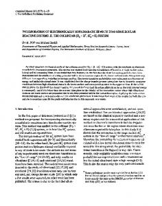
of different data sources and data formats in which the data are generated and saved. Veracity stands for the reliability and accuracy of data. Value denotes the intrinsic value of the data. [12] With the aid of the 5-V model, the digital shadow of the factory is classified as a big data application. Up to 20 GB of image material are generated every second just from the cameras mounted to the hall ceiling alone and are processed in realtime (velocity). To allow any mistakes to be corrected, these data are saved for up to half an hour (volume). Data from numerous other measuring systems also needs to be integrated into the digital shadow (variety). Data reliability and accuracy, as well as data processing (veracity) are key since the data form the basis of guidelines and decisions (value). 3.2. Converting and merging data to generate a digital shadow of the factory If the position of the various measuring systems in space is known, all objects measured can be transformed from the local coordinate system of the respective measuring system into the absolute factory coordinate system. Data measured by the different measuring systems at a specific point in time are decentrally converted into 3-D models and, where possible, identified. If necessary, the measured data points are also transformed from the polar/spherical coordinate system of the measuring sensors into a Cartesian system. From the position and orientation data recorded by the measuring system, the coordinate transformation applicable at the time is then calculated in the factory coordinate system and applied to the 3-D model. The model is marked with a stamp indicating the location, orientation and moment in time. It is also marked with a tolerance depending on the respective accuracy class of the measuring system and the data are then filed centrally on a server. Software then merges the 3-D models obtained from all measuring systems of a point in time in the factory coordinate system. Due to the measuring systems’ varying degrees of accuracy and resolution, there may be discrepancies in position and orientation. These can then be corrected based on the accuracy classes of the measuring systems and a plausibility check to avoid measurement errors. After the merging step, any objects whose contours have not been fully recorded and which therefore cannot be identified decentrally, are compared with objects filed in the factory database and identified (see Figure 1).
Figure 1. Procedure for standardizing data
J. Siegert et al. / Procedia Manufacturing 9 (2017) 127 – 134
133
The factory models generated from the time recordings of the factory are then placed one behind one another to create a realtime digital shadow of the overall production system. To verify the accuracy of the digital shadow, 18 beamers are mounted to the IFF hall ceiling, which project the digital shadow of the production system onto the learning factory on a scale of 1:1. Via the cameras attached to the hall ceiling, any discrepancies between the projection and the real production system are pinpointed, such as incorrectly positioned manufacturing equipment or a time delay when recording the movement of a workpiece. These discrepancies show up inaccuracies, or errors made when acquiring data or merging the digital shadow, which can be utilized to automatically correct the digital shadow via the cameras’ feedback loop. 4. Advantages of the digital shadow Once data have been acquired from all objects in the production system over a longer period, and provided the digital shadow matches the real production system, the dependencies of objects can be filed in the system. This is achieved using the diverse controllers and regulating systems of the learning factory and AGVs. Correlation analyses give information about hidden dependencies. These dependencies lead to the formation of subsystems, such as the material supply loop or workflow. The production system is divided (downscaled) into separate layers by the sub systems formed (see Figure 2a). Due to the complexity of the system, a simulation of the entire production process in realtime is not possible. However, if the production system is split into separate layers, less complex sub-systems can be simulated in realtime. The simulation results from the various layers can then be upscaled again. The different layers can be faded in and out during the simulation to focus on and optimize individual subsystems or factory areas. By modeling the production system in realtime, the simulations used to aid decision-making are always based on up-to-date information, such as the current factory layout. This avoids erroneous simulations due to incorrect initial data about the state of production system and reduces the risk of making wrong decisions. Simulations can also be continuously compared with the digital shadow, i.e. the state of the real production system and any discrepancies identified, which could indicate deficiencies in the simulation step, previously unapparent problems or imminent malfunctions. Through entering current data into the simulation, any discrepancies can be integrated into the simulation and their consequences calculated in advance, thus enabling the relevance of the discrepancy to be determined. If there is a risk of a malfunction, the cause of the deviation can be narrowed down by focusing on individual layers and backcalculating the changes occurring. This enables malfunctions to be avoided and downtimes to be reduced. By detecting the tiniest discrepancies and their causes, both the production system and the simulation can be continuously optimized. Beamers mounted to the hall ceiling can be used to project the simulation onto the shopfloor (see Figure 2b). Discrepancies between the simulation and the real production system become immediately apparent to the worker and, if desired, can also be highlighted to point out a possible malfunction to the worker. Once the cause of the
Figure 2. (a) Layers of the digital shadow, (b) Simulation projected onto the production hall
134
J. Siegert et al. / Procedia Manufacturing 9 (2017) 127 – 134
malfunction has been narrowed down through reverse computation, a beam of light guides the skilled worker in charge of rectifying such problems to the cause of the malfunction. One possible scenario in IFF’s Learning Factory shows an AGV which has been delayed during material allocation. By capturing these data and matching them with the simulation of the factory, the delay will be detected and a rescheduling can be initiated feeding back the necessary changes and instructions, e.g. loading data, routes and safety instructions, into the factory. The scenarios presented can be used for trainings in the learning factory focusing on I4.0 issues and may be adapted to the individual participants’ needs. 5. Summary Based on the method published in 2012 for automatically comparing the real factory with a digital data model [8], IFF has developed a method and implemented it in the learning factory “advanced Industrial Engineering”, which makes the complexity of a constantly-changing factory manageable. Thanks to the development of a standardized coordinate system, the digital shadow of the complete factory based thereon and the resulting realtime simulations, any discrepancies between simulations and the real factory can be detected. This allows imminent problems to be recognized and solved before they arise, as well as reducing downtimes and minimizing the risk of making wrong decisions. The production system can also be continuously improved by projecting simulations results onto the real factory. References [1]
Bauernhansl, T., 2014. Die Vierte Industrielle Revolution – Der Weg in ein wertschaffendes Produktionsparadigma, in: Bauernhansl, T., Hompel, M. ten, Vogel-Heuser, B. (Eds.), Industrie 4.0 in Produktion, Automatisierung und Logistik. Springer Fachmedien Wiesbaden, Wiesbaden, pp. 5–35. [2] Westkämper, E., 2009. Digital production, in: Bullinger, H.-J. (Ed.), Technology Guide. Springer Berlin Heidelberg, Berlin, Heidelberg, pp. 482–485. [3] Ashby, W.R., 1956. An introduction to cybernetics. John Wiley & Sons Inc., New York. [4] Matysczok, C., Meyer, D. Erfolgsfaktoren bei der strategischen Einführung der Digitalen Fabrik, in: , ZWF, 104 (2009), pp. 27–31. [5] Constantinescu, C., Kluth, A., 2011. Flexible Connection of Product and Manufacturing Worlds: Concept, Approach and Implementation, in: New Worlds of Manufacturing. 44th CIRP International Conference on Manufacturing Systems, 1-3 June 2011, Madison, Wisconsin, USA. Proceedings. CIRP International Conference on Manufacturing Systems 44, 2011, Madison; ICMS, Madison, WI, U.S.A. [6] Milberg, J., Ebner, C. Verfügbarkeit von Werkzeugmaschinen, in: VDI-Z – Düsseldorf : Springer-VDI Verlag, Bd. 136 (1994) Nr. 1/2, pp. 32-33. [7] Reithofer, N., 1987. Nutzungssicherung von flexibel automatisierten Produktionsanlagen, Springer Berlin Heidelberg, Berlin, Heidelberg. [8] Bauernhansl, T., Siegert, J., Böck, J., Haag, H. Fabrikoptimierung mit Kamera und Beamer: Das "Shop Floor Analyzing Visualization Center" integriert digitale und reale Welt, in: , wt Werkstattstechnik online. - Düsseldorf : Springer-VDI Verlag, Bd. 102 (2012), Nr. 3, pp. 94–97. [9] Riffelmacher, P., Dinkelmann, M., Westkämper, E., 2011. Configuration and Structure of the IFF Learning Factory Advanced Industrial Engineering, in: Spath, D., Ilg, R. (Eds.), Innovation in product and production. July 31 - August 4, 2011 in Stuttgart, Germany ; conference proceedings ; 21th International Conference on Production Research, ICPR 21. Fraunhofer Verlag, Stuttgart. [10] Dinkelmann, M., Riffelmacher, P., Westkämper, E., 2012. Training concept and structure of the Learning Factory advanced Industrial Engineering, in: ElMaraghy, H.A. (Ed.), Enabling Manufacturing Competitiveness and Economic Sustainability. Proceedings of the 4th International Conference on Changeable, Agile, Reconfigurable and Virtual production (CARV2011), Montreal, Canada, 2-5 October 2011. Springer-Verlag Berlin Heidelberg, Berlin, Heidelberg, pp. 624–629. [11] Albers, Jens, 2014. RTLS - Real Time Locating Systems: Ein AIM-White-Paper. https://www.avus-services.de/files/download/aktuelles/neuigkeiten/RFID/AIM%20WhitePaper%20RTLS-2014%20V2-0_Content.pdf. (Last checked: 17.02.2017) [12] Wissenschaftliche Gesellschaft für Produktionstechnik Wgp e.v. (Ed.), 2016. WGP-Standpunkt Industrie 4.0.