Star-Graph Based Multistage Interconnection Network for ATM Switch Fabric C.P. Ravikumar Department of Electrical Engineering Indian Institute of Technology New Delhi, Hauz Khas 110016, INDIA
[email protected]
G. Manimaran National Informatics Center Lodhi Road, New Delhi 110013 INDIA
[email protected] efficiency, complexity, modularity and cost. Fast packet switches can be classified based on several issues [2] such as (a) the design or structure of the switch fabric, (b) the type of switching service they provide internally (blocking/non-blocking), and (c) the location of queues (queues are employed to handle output port blocking).
Abstract This paper considers a multistage interconnection network based on the Indirect Star Graph topology as a candidate for an ATM (Asynchronous Transfer Mode) switch fabric. We consider both buffered and unbuffered versions of the indirect star. The performance of three existing routing algorithms is studied, and it is found that the packet acceptance probability offered by these algorithms is unsatisfactory. We propose two solutions to alleviate the problem (i) a modification of the indirect star topology, which we call Star Net, and (ii) an adaptive routing algorithm based on the concept of packet priorities. We study the performance of the proposed performance enhancement schemes through simulation.
1.1 Requirements of ATM switch fabrics Some of the desirable requirements of an ATM switch fabric are its capability to support multicasting, and a non-blocking switch fabric with unbuffered switch elements. Multicast switches have the capability of sending packets from one input to many outputs. Teleconferencing, video distribution, and multi-way telephone calls are examples of applications requiring such facility [2]. The Starlite switch [2], Turner's broadcast packet switch and Lee's non-blocking copy network are able to multicast packets [2].
1. Introduction In order to meet the challenges posed by the forthcoming Broadband Integrated Services Digital Networks (B-ISDN), a unique transport network based on the Asynchronous Transfer Mode (ATM) technique has been proposed in the recent past. ATM provides a B-ISDN interface flexible enough to support all of today's services (voice and data) as well as future narrowband services (for data applications) and broadband services (typically for video applications) [9]. ATM uses fixed-size data units, which are easier to handle in comparison to variable-size packets, which makes ATM a leading contender for high-speed packet switching. To support the packet-switching function at very high speeds, hardware solutions are mandatory. ATM is a service-independent switching and multiplexing technique that is totally independent of the underlying transmission technology and the transmission medium. In an ATM network, the user information is transferred through the network in small fixed size units, called cells, each 53 bytes long. A cell includes a payload (48 bytes), which contains the user information, and a header (5 bytes), which specifies the virtual connection of the cell [9].
The examples for sorter-banyan networks are Starlite switch, Hui and Arthurs' packet switch and Sunshine network [2]. The Starlite switch uses a trap network to trap packets destined for the same output port and feeds all but one packet back to the input of the switch, while the winner is routed to its output port. This reentry approach to output contention resolution eliminates the need for buffered switch elements. Hui and Arthurs' packet switch and the multicast switch of Lee et al. implement three phase reservation mechanism to avoid buffering switch elements. The example for buffered switch fabric is buffered Benes network in which each switch element is connected in a Benes topology with buffering at each switch element. When there is a heavy traffic to a few output ports of a buffered multistage interconnection network (hotspot traffic), the performance of the switch deteriorates rapidly due to a phenomenon called tree saturation [5]. Various schemes have been proposed for buffered shuffle exchange [5] to avoid tree saturation and to ensure that hotspot traffic can be supported with little degradation to uniform traffic that is equiprobably destined to other output ports of the switch fabric. Hui and Arthurs' packet switch [2] is an example for input queueing and the Knockout switch [2] based on crossbar network employs output queueing. The Starlite switch employs mixed shared
Several interconnection networks have been investigated in the literature for fast packet switching [6, 4, 2]. Each design has some merits and demerits related to
444
queueing. Buffered switch elements pose problems in that it is difficult to estimate the exact buffer requirement and the complexity of the switch increases as the buffer size of the switch element increases. Buffering also leads to problems like tree saturation. Moreover, buffering in lightwave multihop networks requires optoelectronic conversion and vice-versa to buffer the packet in electronic buffer and to route it from the buffer respectively [10].
switching architecture based on the priority based routing algorithm is described in Section 4. Conclusions are presented in Section 5. 2 Indirect Star-I Network The Star graph is a member of class of graphs called Cay ley graphs [1]. An n-star graph consists of n! nodes labelled using permutations on n symbols. An edge between two nodes is defined by the application of a generator gi; where g, is a member of generator set g = {g2» §3' - > gJ- Two nodes labelled S and D are connected by an edge iff D can be obtained by applying the generator gj on S, we write D = gj(S). The application of generator g, is defined as swapping the first (left most) symbol of S with i-th symbol of S. For example, a 5-star consists of 120 nodes; the node labelled 12345 is connected to nodes labelled 21345, 32145, 42315 and 52341 by applying generators g2, g3, g4 and g5 respectively on 12345. The following properties of the Star graph were proved in [1]. An n-star consists of n! nodes and n!(n-l)/2 edges. Star graph is node and edge symmetric. The diameter of the n-star is \-3(n-\)l2-l .The average distance K^ between two nodes in an n-star is n+2/n+Hn-4, where Hn is the n-th Harmonic number.
We believe that the performance of a switch fabric is determined by both the architecture and the routing algorithm. By adopting good routing rules and heuristics the performance of the switch can be enhanced. It is also important that some scheme must be devised to handle output port blocking. Deflection routing is one such scheme under which, a packet may be intentionally misrouted to avoid buffering at an intermediate route. A slightly longer path may be required when deflection routing is used. Shuffleout network with deflection routing has been proposed in [4] for ATM switching. The performance analysis of shuffleout network with deflection routing for multihop lightwave networks is done in [11]. The authors of [11] have proposed Priority based heuristics for deflection routing and considered parameters such as mean number of hops, the lost packet performance, the queueing delay and saturation throughput for performance analysis. They considered distance-age priority, age-distance priority and no-priority schemes and showed that distance is a better discriminator than age since the distance-age priority mechanism can provide lower delay, lower packet loss and higher saturation throughput.
2.1 Routing Algorithms for Star graph Three routing algorithms are known for the Star Graph, namely, the algorithm proposed in [1], the Cycle Merging Algorithm (CMA) given in [3], the E-Star Algorithm (ESTAR) of [3]. 2.1.1 Akers-Krishnamurthy Algorithm This routing algorithm takes no more than Kn hops to route from any given source node S to a destination node D. The routing algorithm is defined by the following two rules which give the next node for a given source node S to destination node D. Rule 1 : if first symbols of S and D are equal, i.e. S(l) = D(l), apply generator g: on S such that S(i) * D(i). Rule 2 : if S(l) * D(l), apply generator gj on S such that S(l) = D(i). For example, the routing path from source node 4132 to destination node 4213 is obtained by repeatedly applying the above two routing rules until the destination node is reached. For clarity, the (rule,generator) pair used at each step is specified in the arcs along the routing path. 4132-(l,2)-»1432-(2,3)-»3412-(2,4)-»2413-(2,2)->4213 Due to its rich interconnection, there are multiple shortest paths between two nodes in a Star graph. For the above example, the other two shortest paths are : 4132-(l,3)->3142-(2,4)->2143-(2,2)->1243-(2,3)->4213 4132-(l,4)->2134-(2,2)->1234-(2,3)->3214-(2,4)->4213
In this paper, we consider multistage interconnection networks based on Star graphs [1] for ATM switching. We consider the Indirect star-I network proposed by Yoon and Lee in [7] (see Section 2). We describe the simulation of the Indirect star-I networks using three known routing algorithms for Star graphs (Section 3). The packet acceptance probability of these three algorithms is unsatisfactory for recommending the Indirect star-I network as a candidate for ATM switching fabric. Therefore, we propose improvements to Indirect star-I in terms of architecture and routing algorithms (Sections 3 and 4). We consider the buffered version of Indirect Star-I networks for performance study in Section 3. A technique based on generator matrix has been attempted to get better acceptance probability (see Section 3). We propose a priority-based deflection routing scheme for Indirect star-I networks, and a new
2.1.2 Cycle Merging Algorithm (CMA) The CMA transforms the source permutation S into
445
destination permutation D. To do this, the cycle structure of S w.r.t. D is used. The source would have been transformed to D when this cycle structure consists of n unicycles. This algorithm takes maximum of Kn steps to route packet from a given source S to destination D. This is achieved in two phases. Algorithm Cycle_Merge(S,U) begin Phase-1: Find first i such that S(i) * D(i) and S(i) is not in the same cycle as D(l). if no such i found then goto Phase-2. Swap S(i) with S(l). goto Phase-1. Phase-2: Find i such that S(l) = D(i). if i = 1 then stop. Swap S(l) with S(i). goto Phase-2. end. E.g., let S = 123546 and D = 451236. The cycle structure of S w.r.t. D is (143) (25) (6). Here the number of unicycles u = 1 and we merge the remaining two unicycles by swapping symbols 1 and 2. The resulting cycle structure is (24315) (6) and the permutation is 213546. Four more swaps can transform S into D, and the intermediate nodes will be 513246, 153246, 351246, and 451236.
2.2 Indirect Star-I network The Indirect Star-I network, proposed by Lee and Yoon [7], is a multistage interconnection network obtained by unfolding the Star graph. An Indirect n-star-I network has K,,+l switching stages numbered from 1 to Kn+1. Each stage consists of n! switch elements labelled with n! permutations. Each switch element in the first stage is a (lxn) demultiplexer, and each switch element in the last stage is an (nxl) multiplexer. All switch elements in the middle stages are (nxn) crossbar switches. The n input and output links of a switch element are labelled as g,, g2, ..., gn from top to bottom, where g; is a member of generator set g = {g,, g2, ..., g n }. Thus, n output links of a switch provide the (n-1) generators of the n-star graph, plus the identity generator, g,. The connections between switching stages reflect the actions of the generators associated with the output links; output link g, of switch element S is connected to input link g, of switch element T at the subsequent stage, where g;(S) = T; Figure 1 shows an Indirect 3-star-I network [7]. Stc
2.1.3 E-Star Algorithm This algorithm is based on the Hierarchical property of the Star graph and takes 2n-3 hops in the worst case for routing packets between two nodes. The following algorithm finds the routing path for a given source node S to destination node D. Algorithm E-Star(S,D) begin 1. if S = D then stop; else begin 2. Find largest i such that D(i) * S(i) if S(l) = D(i) then begin T = gi (S); E-Star(T,D); end else begin 3. Find j such that S(j) = D(i); T = gj(S); E-Star(T,D); end end end. E.g., a packet originating at node 2341 and intended for destination node 1234 will be routed along the path 2341 ._> 4321 - > 1324 - > 3124 - > 2134 --> 1234.
Figure 1 : Indirect 3-Star Graph The routing algorithms of Star graph such as AKA and CMA can be used for Indirect star-I networks also. The E-Star algorithm can be used for the extended version of indirect star-I network in which the number stages is equal to (2n-3) + 1, where (2n-3) is the worst case communication distance obtained using E-Star algorithm. The authors of [7] have considered the case wherein a routing tag is generated using Akers-Krishnamurthy algorithm at the input itself and is appended to the packet. The routing at each switch element is done by looking at the routing tag corresponding to the stage to which the switch element belongs. For example, to route from input port 213 to output port 321, the routing tag is (See Figure 1). The authors of [7] proposed another network, called Indirect star-II, and compared it with crossbar and Indirect-cube networks using performance studies such as Acceptance probability Versus Network size and Acceptance probability versus
446
Packet arrival rate. They concluded that the Indirect Star-II exhibits higher acceptance probability than Indirect-Cube and can be used when the size of network is closer to factorial.
acceptance probability and they are superior to the ESTAR algorithm. Therefore, it can be concluded that the Indirect star-I network along with the above mentioned routing algorithms is not a good interconnection for ATM switching fabric.
2.3 Indirect n-star for ATM switching In the previous section, we have seen that non-blocking routing and multicast support are both requirements of an ATM switching fabric. The work in [7] did not attempt to carry out the routing in a more conflict-free manner and also they did not consider the buffered Indirect Star networks for performance study. Also, the assumption that the rejected packets are lost is not a practically valid assumption. Also, the authors did not provide algorithms for multicasting/broadcasting in the Indirect Star network. One of the aims of this paper is to make the routing in Indirect Star-I network in a conflict-free manner since we intend to use the Indirect Star-I as an ATM switching fabric. We also propose enhancements to the Indirect Star-I which will enable efficient packet switching. The following two sections describe attempts to achieve this.
1-0 0-9 0.8 0-7
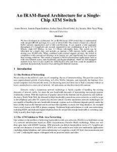
3 Architectural Enhancements to Indirect Star-I Simulation results of the Indirect star-I using the three routing algorithms introduced in section 2 are presented here. We consider both buffered and unbuffered version of Indirect Star-I. For the simulation results presented in this paper, we assume the following model, unless stated otherwise, (a) Packets are generated independently at each source port with arrival rate Lambda per stage cycle. (b) Each source node generates fixed size packets uniform over all destination ports, (c) In the case of an unbuffered network, the conflicts are resolved randomly, i.e. one of the contending packets is routed and the rest of the packets are rejected and assumed to be dropped. (d) In the case of a buffered network, the rejected packets are buffered in the switch element.
0-6
0-5 0.0
0-2
0-4
0.6
OS
i.o
Arr'ival r a t e ( X )
Figure 2 : Performance of Unbuffered Indirect-Star-I
3.1 Unbuffered Network The simulation results of Indirect star-I network using algorithms such as AKA, CMA and ESTAR is presented here. The following parameters are considered for performance analysis, (a) Packet acceptance probability versus Network size for random samples whose destination requests form permutations, (b) Packet acceptance probability versus Arrival rate by fixing the network size.
3.2 Buffered Network In this section, to improve the performance of the Indirect Star-I, we consider the Indirect star-I network with buffered switching elements. During routing of packets from input ports to output ports, if contention occurs for a particular link of a switch element among the incoming packets and the packets that are already in the buffer, then the buffered packets are given preference for routing over the incoming packets. If there is no packet in the buffer then one of the contending packets is chosen randomly for routing. The unrouted packets are buffered inside the switching element. The buffers are assumed to be FIFO. By adopting the above approach, we ensure that no packet gets delayed indefinitely and the worst case packet delay in terms of the number of hops is lower bounded by nKn.
The performance of the network is shown in Figure 2. From the plots, it can be observed that the packet acceptance probability starts decreases as the network size increases. This behavior is consistent with all the three routing algorithms. Among the three routing algorithms, the AKA and CMA give more or less the same
We consider AKA and CMA algorithms and the following issues for simulation, (a) Packet loss versus Network size with fixed packet arrival rate by varying the buffer size of switch elements, (b) Packet loss versus Arrival rate with fixed network size by varying the buffer size of switch elements.
447
The simulation results are plotted in Figure 3. The simulation result shows that the optimal buffer size for (n! x n!) size switch fabric is upper bounded by 3Kn.
Star
0-2
0-A
routing algorithm requires the use of an m-stage Indirect Star-I. Thus, the objective of this approach is to find a matrix with minimum number of columns. Since we know that there are p paths originating from any source node, the minimum number of columns of a generator matrix is lower bounded by n!/p. We give examples of such a matrix for 3-star and 4-star. Each entry i in the following matrices corresponds to generator g,. 2 3 2 3 2 3
2 3 4 2 3 4 3 2 3 2 M4= [ 3 4 2 3 4 2 4 3 4 3 ] 4 2 3 4 2 3 2 4 2 4
size
0-6
While M3 has the optimum number of columns (3!/2 = 3), the matrix M4 has 10 columns as opposed to the lower bound of (4!/3 = 8). The generator matrix Mn is w.r.t. the identity permutation labelled node In off-line. For routing from any arbitrary source S to destination D, the source is relabelled as S = In and the destination is relabelled as D = S-'(D). For example, let S = 3142 and D = 4231 then S = 1234 and D = 2143. We maintain the generator matrix Mn and p lists of nodes S, that are reachable using i-th row of Mn, l