energies Article
State of Charge-Based Active Power Sharing Method in a Standalone Microgrid with High Penetration Level of Renewable Energy Sources Yun-Su Kim *, Chul-Sang Hwang, Eung-Sang Kim and Changhee Cho Korea Electrotechnology Research Institute, Changwon 51543, Korea;
[email protected] (C.-S.H.);
[email protected] (E.-S.K.);
[email protected] (C.C.) * Correspondence:
[email protected]; Tel.: +82-55-280-1316 Academic Editor: Neville R. Watson Received: 10 March 2016; Accepted: 17 June 2016; Published: 23 June 2016
Abstract: Standalone microgrids, which are mainly constructed on island areas have low system inertia, may result large frequency deviations even for small load change. Moreover, increasing penetration level of renewable energy sources (RESs) into standalone microgrids makes the frequency stability problem even worse. To overcome this problem, this paper proposes an active power sharing method with zero frequency deviations. To this end, a battery energy storage system (BESS) is operated as constant frequency (CF) control mode, whereas the other distributed generations (DGs) are operated as an active and reactive power (PQ) control mode. As a result, a state of charge (SOC) of the BESS is changed as the system load varies. Based on the SOC deviation, DGs share the load change. The SOC data is assumed to be sent via communication system, hence the communication time delay is considered. To enhance reliability, controllers of DGs are designed to take account of the failure of communication system. The simulation results show that active power can be shared among DGs according to desired ratio without frequency deviations even for large variation of output power of RESs. Keywords: constant frequency (CF); renewable energy source; state of charge (SOC)-based active power sharing; standalone microgrid; zero frequency deviation
1. Introduction The demand of electric energy has been continuously increased [1], whereas its supply has been saturated due to geographical, social, and environmental problems, such as spatial limitation, objection of residents, and pollutions. As a solution for electrical energy balancing problem, distributed generations (DGs) and microgrids have been increasingly penetrated into power systems. On the other hand, renewable energy sources (RESs) have also been drastically increased in terms of a solution for environmental pollutions [2]. Introduction of both a microgrid and a RES has launched many new projects, such as [3–5], which attempt to interconnect RESs into isolated power systems (e.g., remote islands, deserts), thereby constructing a standalone microgrid with high RESs penetration level. Island areas, which are target sites for constructing standalone microgrids, are typically in a circumstance of abundant energy sources of wind (in case of seashores of islands) and/or solar irradiance (in case of deserts). However, standalone microgrids have low system inertia and this may cause large frequency deviation even for small load change. Moreover, increasing penetration level of RESs into standalone microgrids makes the frequency stability problem even worse. In conventional power systems, frequency deviation is inevitable if load and/or output power of RESs are changed. Besides, the active power sharing is based on frequency deviations. Typically, in remote islands, the grid voltage is formed by diesel generators and hence the system frequency is
Energies 2016, 9, 480; doi:10.3390/en9070480
www.mdpi.com/journal/energies
Energies 2016, 9, 480
2 of 13
directly related to the inertia generators. Since the inertia of a small isolated power system is low, large frequency deviations may be occurred by change of load conditions. On the other hand, in standalone microgrids with inverter-interfaced DGs, active power-frequency (P-f ) droop control method has been used. Though this system has no mechanical inertia, P-f droop control method emulates the characteristics of synchronous generators, and hence the system frequency is deviated proportional to both a droop coefficient and the amount of load change. Consequently, the frequency deviation is inevitable in this case too. The active power sharing methods in standalone microgrids can be categorized into two types—whether they use the droop control or not [6]. Most of them adopt the frequency droop control which has been used in the conventional power system composed of large synchronous generators [7–10]. However, since standalone microgrids have low system inertia, the frequency is likely to be largely deviated from its nominal value. As opposed to the conventional method, Vandoorn et al. [11] and Yu et al. [12] proposed active and reactive power (PQ) sharing method based on voltage and frequency deviation, respectively. However, it is effective only in low voltage networks. Moreover, reactive power sharing is based on the frequency, thereby the frequency deviation cannot be prevented. In [13], non-droop-based power sharing method using the communication infrastructure was proposed. However, the frequency deviation cannot be prevented if the load change occurs due to communication time delay. References Lopes et al. [14] and Chuang et al. [15] also proposed a centralized control method. However, they still adopted the frequency droop control method, thereby the frequency deviation is inevitable. The frequency variation during load condition change is one of the main reasons that the penetration level of RESs cannot be grown in standalone microgrids. However, the frequency deviation is necessary for active power sharing according to the conventional control method. In this paper, the active power sharing method without the frequency deviation in a standalone microgrid with high RESs’ penetration level is proposed. To this end, a battery energy storage system (BESS) acts as constant frequency (CF) control mode, while the other DGs share active power based on a state of charge (SOC) deviation instead of the frequency deviation. The active power sharing methods are categorized as a primary and a secondary SOC control, which are to cope with transient load changes and the SOC deviations, respectively. The rest of this paper is organized as follows. Section 2 shows the details of SOC-based active power sharing method. Section 3 describes the system configurations. Section 4 shows the case studies and Section 5 outlines the conclusion. 2. State of Charge-Based Active Power Sharing Method In order to eliminate the frequency deviations under load condition variations, decoupling of active power and frequency and coupling of active power and SOC of a BESS are proposed in this paper. To this end, a BESS must be connected to a standalone microgrid and be operated in a CF control mode whereas the other DGs must be controlled as a PQ control mode. 2.1. Relationships between Active Power and State of Charge of a Battery Energy Storage System The key idea of this paper is to relate the whole load variation in a standalone microgrid to the SOC of a BESS. To this end, only a single BESS whose SOC is determined to be related the load variation should be operated in a CF control mode. The output frequency of the BESS is determined by the inverter and hence it can change the output voltage angle instantaneously unlike synchronous generators. In this way, during the load variation of the system, the frequency can be maintained at the desired value by the BESS, and thereby the output of the BESS follows the load variation. Since the output of the BESS directly affects the SOC, the SOC is changed as the load varies.
Energies 2016, 9, 480
3 of 13
The relationship between the output active power and the SOC of the BESS can be expressed Energies 2016, 9, 480 3 of 12 as [16]: w PBESS ˆ Prate SOC i ´PBESS is the output active power of the BESS, Prate is the (1) where SOCi is the initial value of “ theSOC SOC, VDC ˆ IDC,rate ˆ Crate rating power of the BESS, VDC is the DC-link voltage of the battery, IDC,rate is the rated current of the
where SOCi is the initial of the SOC, theinitial output active power of the Pratebyis the BESS isThe battery, and Crate is thevalue rate capacity of thePBESS. value of SOC should be BESS, estimated ratingmeasuring power ofthe thebattery BESS, voltage, V DC is the DC-link the the battery, is SOC the rated current however it isvoltage assumedofthat initialIDC,rate value of is given in thisof the study. VDC varies as the of SOC but its variation is of relatively small and it can be by battery, andPractically, Crate is the rate capacity thechanges BESS. The initial value SOC should be estimated maintained constantly by a DC/DC converter. Note that for exact analysis, studies on measuring the battery voltage, however it is assumed that the initial value of SOC is given inverter in this study. dynamics, variation ofSOC VDC must be considered also. Foristhe sake of convenience, DC is assumed Practically, V DCthe varies as the changes but its variation relatively small and itVcan be maintained to be constant in this paper. The derivative of Equation (1) gives: constantly by a DC/DC converter. Note that for exact analysis, studies on inverter dynamics, the dSOC variation of V DC must be considered also. For the sake of convenience, V DC is assumed to be constant K BESS PBESS (2) t in this paper. The derivative of Equation (1) dgives: where KBESS is a constant value since VDC is assumed to be constant. dSOC From Equation (2), it can be noticed that “ the´K SOC isPchanged only if the output active power of (2) BESS BESS dt the BESS is changed. The relationship between active power and SOC is shown in Figure 1, where DG,max indicates the maximum output power of the BESS and a DG unit which shares wherePBESS,max KBESS and is a Pconstant value since V DC is assumed to be constant. active power with the BESS, respectively. Since theisoutput active the BESS affects theof the From Equation (2), it can be noticed that the SOC changed onlypower if the of output active power derivative of the SOC proportional to KBESS, the slope ms can be determined as a droop coefficient of BESS is changed. The relationship between active power and SOC is shown in Figure 1, where PBESS,max a DG unit. The DG unit with droop coefficient ms shares the transient load with the BESS. The details and PofDG,max indicates the maximum output power of the BESS and a DG unit which shares active the transient load sharing is discussed in Section 2.3. To keep the SOC level constant, PBESS at steady power with the BESS, Since active of the BESS affects the the derivative state should be 0 respectively. (see Point A of the the BESSoutput in Figure 1) power since PBESS other than 0 occurs SOC of the SOC proportional to K , the slope m can be determined as a droop coefficient of a DG unit. The s BESS deviations. At this point (the steady state), the output of a DG unit is PDG,A. Since the BESS is the only DG unit with droop coefficient m shares the transient load with the BESS. The details of the transient unit that controls frequency, the s output active power of the BESS is the only output power that reacts to generation mismatch. the mismatch of theconstant, BESS and P the derivative of the SOC load sharing is discussed inIfSection 2.3. Tooccurs, keep the theoutput SOC level at steady state should BESS will Point move to thethe point B (Pin BESS,B and −SOC B, respectively) Figure 1. Simultaneously, the DG unit be 0 (see A of BESS Figure 1) since PBESS otherinthan 0 occurs the SOC deviations. At this will support the BESS with the amount of output power inversely proportional to m s. From Equation point (the steady state), the output of a DG unit is PDG,A . Since the BESS is the only unit that controls (2) and Figure 1, the following equations can be established:
frequency, the output active power of the BESS is the only output power that reacts to generation SOCB of 0) KBESS ( PBESS,B mismatch. If the mismatch occurs, the(output the BESS and 0) the derivative of the SOC will (3) move to the point B (PBESS,B and ´SOCB , respectively) in Figure 1. Simultaneously, the DG unit will support the (SOCB 0) mS ( PDG,B PDG,A ) (4) BESS with the amount of output power inversely proportional to ms . From Equation (2) and Figure 1, Equations (3) and (4)beare the basic principles for the primary SOC control unit which will be the following equations can established: discussed in Section 2.3. If the load condition varies, the output power of the BESS moves from 0 to PBESS,B and the output power of p´SOC the DG moves from PDG,A to PDG,B. If ms is 0, which means that there is B ´ 0q “ KBESS pPBESS,B ´ 0q no DG unit supporting the SOC, the output and the SOC of the BESS deviate larger. The large deviation of the SOC may causep´SOC fully charged/discharged state of the BESS quickly and this leads the B ´ 0q “ mS pPDG,B ´ PDG,A q BESS to trip out from the system.
Figure 1. Relationship between activepower power and and state state of DG: distributed generation; Figure 1. Relationship between active ofcharge charge(SOC). (SOC). DG: distributed generation; and BESS: battery energy storage system. and BESS: battery energy storage system.
(3) (4)
Energies 2016, 9, 480
4 of 13
Equations (3) and (4) are the basic principles for the primary SOC control unit which will be discussed in Section 2.3. If the load condition varies, the output power of the BESS moves from 0 to PBESS,B and the output power of the DG moves from PDG,A to PDG,B . If ms is 0, which means that there is no DG unit supporting the SOC, the output and the SOC of the BESS deviate larger. The large deviation of9,the Energies 2016, 480 SOC may cause fully charged/discharged state of the BESS quickly and this leads 4 ofthe 12 BESS to trip out from the system. In the subsequent subsections, control methods of the BESS and the other DGs, which couple the change of load condition and the SOC of the BESS, are introduced. The control methods methods of DGs to support the SOC control are also discussed. 2.2. Control Control of of the the Battery Battery Energy Energy Storage Storage System 2.2. System A BESS BESS operated operated as as aa CF CF control control mode mode must must be be connected connected in in aa standalone standalone microgrid microgrid in in order order to to A apply the proposed method. In this case, only a single BESS must be operated as a CF control mode. apply the proposed method. In this case, only a single BESS must be operated as a CF control mode. By applying applying aa CF CF control control mode mode to to the the BESS, BESS, the the output output active active power power of of the the BESS BESS (and (and only only the the BESS) BESS) By responds to to all all changes changesof ofload loadconditions, conditions,such suchasaschanges changesofofload loadoror RESs’ output. If other DGs responds RESs’ output. If other DGs or or BESSs are operated in a frequency control mode, they also respond to the load change either. To BESSs are operated in a frequency control mode, they also respond to the load change either. To prevent for DGs and/or BESSs must be be operated in ainPQ control mode. The prevent for them themtotorespond, respond,the theother other DGs and/or BESSs must operated a PQ control mode. control scheme of the is shown in Figure 2. 2. The control scheme ofBESS the BESS is shown in Figure
Figure Figure 2. 2. Control Control scheme scheme of of the the BESS. BESS.
Figure 2 shows the BESS controller, where fnom is the nominal frequency, Vnom is the nominal Figure 2 shows the BESS controller, where f nom is the nominal frequency, V nom is the nominal voltage magnitude, PBESS and PBESS,ref are the output active power of the BESS and its reference value, voltage magnitude, PBESS and PBESS,ref are the output active power of the BESS and its reference value, respectively, mp is the frequency droop coefficient, and vabc,ref is the reference voltage of the inverter respectively, mp is the frequency droop coefficient, and vabc,ref is the reference voltage of the inverter of of the BESS. The droop coefficient mp (which is 0.0083 in this study) is determined by dividing the BESS. The droop coefficient mp (which is 0.0083 in this study) is determined by dividing allowable allowable frequency range (0.5 Hz = 0.0083 pu) by the maximum output power of the BESS (1 MW = frequency range (0.5 Hz = 0.0083 pu) by the maximum output power of the BESS (1 MW = 1 pu). 1 pu). In normal condition, switch is connected to node a, whereas in abnormal condition, such as a In normal condition, switch is connected to node a, whereas in abnormal condition, such as a case that case that the SOC data cannot be sent to other DGs due to communication failure, the switch is the SOC data cannot be sent to other DGs due to communication failure, the switch is connected to connected to node b. In this way, the BESS is operated to maintain CF in normal condition. By using node b. In this way, the BESS is operated to maintain CF in normal condition. By using the BESS as the BESS as the only frequency control mode unit, the BESS responds to all changes of load condition. the only frequency control mode unit, the BESS responds to all changes of load condition. If there are If there are two or more BESSs in the system, only one BESS must be controlled in CF control and the two or more BESSs in the system, only one BESS must be controlled in CF control and the others must others must be controlled in PQ control mode in order to apply the proposed control strategy. be controlled in PQ control mode in order to apply the proposed control strategy. If the communication system fails, the present SOC level of the BESS cannot be delivered to other If the communication system fails, the present SOC level of the BESS cannot be delivered to other DGs. Thus, to enhance the system reliability, the switch is connected to node b if the communication DGs. Thus, to enhance the system reliability, the switch is connected to node b if the communication system fails in order for the BESS to be operated as the conventional P-f droop control mode and then system fails in order for the BESS to be operated as the conventional P-f droop control mode and then the other DGs sense the load change by the frequency deviations. the other DGs sense the load change by the frequency deviations. However, the BESS has a capacity limitation which leads the BESS unable to operate consistently However, the BESS has a capacity limitation which leads the BESS unable to operate consistently if it becomes fully discharged. To overcome this problem, other controllable DGs are controlled to if it becomes fully discharged. To overcome this problem, other controllable DGs are controlled to maintain the SOC at a certain level and to share the active power of the system. These types of DG maintain the SOC at a certain level and to share the active power of the system. These types of DG units units are categorized as primary and secondary SOC control units as similar as the conventional are categorized as primary and secondary SOC control units as similar as the conventional primary primary and secondary frequency control units. and secondary frequency control units. By using the BESS as a CF control mode unit and the other DGs as PQ control mode units, two problems related to the rating of the BESS may happen. The first one is that the output power of the BESS may exceed its power rating if a large transient load change occurs. The other is that the BESS may be fully discharged since it cannot control its active power directly. To overcome these problems, some of the controllable DGs in a microgrid have to support transient load change and the others have to maintain the SOC within an allowable range. The primary and the secondary SOC control
Energies 2016, 9, 9, 480 Energies 2016, 480
of 12 5 of513
P-f droop control mode. The control scheme of the P-f droop control mode is same as shown in Figure BESS as to a CF control mode unit and the other DGs as PQ control mode units, 2 with By the using switchthe connected node b. two problems related to the rating of the BESS may happen. The first one is that the output power of the BESS may exceed its power rating if a large transient load change occurs. The other is that the BESS 2.3. Primary State of Charge Control may be fully discharged since it cannot control its active power directly. To overcome these problems, Figure shows the control of the primary SOC controlload DGchange unit, where msothers is thehave droop some of the3 controllable DGs in ascheme microgrid have to support transient and the coefficient (Figure 1), within PDG,o isanthe dispatched power,and PDG,ref QDG,refSOC are control the PQunits reference, to maintain the SOC allowable range.active The primary the and secondary are respectively, vd and andthe vq latter, are d-respectively. and q-component respectively, d and iq arenot d- to and for the former Also noteoutput that it isvoltage, profoundly significant ifor the BESS q-component output current, respectively, i d,ref and i q,ref are the reference values of i d and i q , respectively, be fully charged or discharged because the CF control mode cannot be maintained in this case. In this θ iscase, the some reference angle of the grid-side d- and q-axis voltage, and iabc,reftoisthe theconventional reference current of the of other controllable DGs must change their control mode P-f droop inverter the The DG. The scheme controlofprinciple of the primary unit is shown control of mode. control the P-f droop control mode isSOC samecontrol as shown in Figure 2 withinthethe following equation:to node b. switch connected 2.3. Primary State of Charge Control ( P
DG,B
PDG,A )
K BESS ( PBESS,B 0) mS
(5)
Figure 3 shows the control scheme of the primary SOC control DG unit, where ms is the droop coefficient (Figure 1), PDG,o is the dispatched active power, (3). PDG,ref andthe QDG,ref areand theQ, PQrespectively) reference, which is given by substituting Equation (4) into Equation Since PQ (P respectively, v and v are dand q-component output voltage, respectively, i and i are d- and q d can be expressedd as: q q-component output current, respectively, id,ref and iq ,ref are the reference values of id and iq , respectively, 1.5(vq-axis (6) d id v q iq ) θ is the reference angle of the grid-sidePd-and voltage, and iabc,ref is the reference current of the inverter of the DG. The control principle the primary SOC control unit is shown in the Q 1.5(vof (7) q id vd iq ) following equation: KBESS id,ref and iq,ref can be rearranged as:pP pPBESS,B ´ 0q (5) DG,B ´ PDG,A q “ mS 2 id ,ref ( P iq ) Since vd the PQ (P and Q, respectively) can (8) which is given by substituting Equation (4)into Equation DG,ref vq(3). 3 be expressed as: ` vq iq q) v (6) d i2 dQ iq ,refP“(v1.5pv (9) q id DG,ref d 3 Q “ 1.5pvq id ´ vd iq q (7)
Note that the primary SOC control unit should be installed at the same bus with the BESS since id,ref and iq, ref can be rearranged as: it should rapidly sense the output power of the BESS (see Figure 3 that the primary SOC control unit MConsequently, the primary SOC control receives PBESS as an input) without any communication delay. 2 i “ p P ´ v i q vd of power sharing can be adjusted (8)by q q d,ref the BESS. unit can share transient load change with 3 DG,refThe amount varying ms. With a small ms, which means that the primary M SOC control unit takes a large portion of 2 i “ pv i ´ Q q vdBESS can be decreased. However, (9)too responsibility for transient load change, rating of the q d q,refthe power 3 DG,ref small ms can cause the control instability. So it should be determined appropriately.
Figure the primary primarySOC SOCcontrol controlunit. unit. Figure3.3.Control Control scheme scheme of of the
By using the primary SOC control solely, the SOC cannot be restored to the desired value. To Note that the primary SOC control unit should be installed at the same bus with the BESS since it maintain the SOC within an allowable range, the secondary SOC control should be adopted to some should rapidly sense the output power of the BESS (see Figure 3 that the primary SOC control unit controllable units. receives P DGas an input) without any communication delay. Consequently, the primary SOC control BESS
unit can share transient load change with the BESS. The amount of power sharing can be adjusted by
2.4. Secondary State of Charge Control
Figure 4 shows the control scheme of the primary SOC control DG unit, where SOCd is the SOC value with communication time delay, SOCref is the SOC reference, and mf is the frequency-active power (f-P) droop coefficient. The load-SOC control in Figure 4 is to restore the SOC to the reference
Energies 2016, 9, 480
6 of 13
Energies 2016,m9, .480 6 of 12 varying s With a small ms , which means that the primary SOC control unit takes a large portion
of responsibility for transient load change, the power rating of the BESS can be decreased. However,
value if the m SOC is deviated from its reference value. The terminology “load-SOC” comes from the too small s can cause the control instability. So it should be determined appropriately. load-frequency of the SOC conventional powerthe system the frequency if it isvalue. deviate By usingcontrol the primary control solely, SOCwhich cannotrestores be restored to the desired from its nominal value. Multiple secondary SOC control SOC units can should share the SOC deviations To maintain the SOC within an allowable range, the secondary control be adopted to some according to the PI controller gains. For instance, if the gain ratio of two secondary SOC control units controllable DG units. is 2:1, they share active power with the ratio of 2:1 during the SOC restoration. 2.4.The Secondary Statecontrol of Charge Control f-P droop is to cope with the communication failure. In normal condition, the BESS maintains the4CF, andthe hence the scheme f-P droop control does notcontrol activate. the communication fails, Figure shows control of the primary SOC DGIfunit, where SOCd is the SOCthe load-SOC control cannot be activated since the SOC data cannot be received. In this case, value with communication time delay, SOCref is the SOC reference, and mf is the frequency-activethe secondary SOC control unit shares power by sensing same way as power (f -P) droop coefficient. The active load-SOC control in Figurethe 4 isfrequency to restore deviation the SOC toas the reference in value the case of conventional standalone microgrids. If the switch of the BESS controller is connected if the SOC is deviated from its reference value. The terminology “load-SOC” comes from the to node b (Figure 2),control the frequency varies as the loadsystem condition is restores changed. the controller shown load-frequency of the conventional power which theWith frequency if it is deviate its nominal Multiple secondary units canshare share the SOCpower deviations in from Figure 4, the value. secondary SOC control SOC unitcontrol can always active no according matter the to the PI controller ForMoreover, instance, if it thedoes gain not rationeed of two secondary units is 2:1, modes they communication failsgains. or not. any switch SOC that control converts control share active power with the ratio of 2:1 during the SOC restoration. between the load-SOC control and f-P droop control.
Figure SOCcontrol controlunit. unit. Figure4.4.Control Controlscheme scheme of of the the secondary secondary SOC
The coordination process between the BESS, the primary and the secondary SOC control units The f -P droop control is to cope with the communication failure. In normal condition, the BESS is as follows: maintains the CF, and hence the f -P droop control does not activate. If the communication fails, the load-SOC cannot be activated the varies; SOC data cannot be received. In this case, the secondary (1) The control load (or the RESs’ outputsince power) SOC control unit shares active power by sensing deviation as same way as in the case (2) The output power of the BESS and hence the the frequency SOC is changed; of conventional standalone microgrids. If the switch of the BESS controller is connected to node (3) The primary SOC control unit supports the BESS by changing its output power based on bthe (Figureoutput 2), the power frequency varies as condition is changed. With the controller shown in Figure 4, deviation ofthe theload BESS; the secondary SOC control unit can always share active power no matter communication fails SOC or (4) After a small communication time delay, the SOC deviation is the sent to the secondary not. Moreover, it does notthey needrestore any switch that to converts control modes between the load-SOC control control units and the SOC the desired value. and f -P droop control. TheConfiguration coordination process between the BESS, the primary and the secondary SOC control units is 3. System as follows:
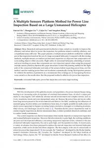
Figure 5 shows the microgrid tested in this paper which is referred from [17,18] with slight (1) The load (ormicrogrid’s the RESs’ output power) varies; modification. The nominal voltage and frequency are 13.8 kV and 60 Hz, respectively. (2) The output power of the BESS and hence the SOC isthe changed; The standalone microgrid is composed of the loads, 1-MW/2-MWh BESS, three controllable (3) The primary SOC control unit supports the BESS by changing its output power (LCs), based on thethe 2-MW DGs, one uncontrollable 2-MW DG, the transformers, the local controllers and output power deviation(MGCC). of the BESS; microgrid central controller The MGCC collects the weather and load forecasting data, (4) After a small communication time delay, (which the SOCare deviation is sent to optimization the secondaryalgorithms) SOC control to the SOC data, etc., and then gives references acquired from and they restore theand SOCthe to the desired value. as an energy management system (EMS) in the LCsunits which control the DGs BESS. It operates the microgrid. However, in this paper, the MGCC is used only for the SOC data exchanging. Since neither inverter switching dynamics nor harmonics is considered, inverters in the DG units and the BESS are assumed as ideal sources. Since the BESS is controlled as to maintain the system frequency and voltage (CF control mode), it is modeled as an ideal voltage source. The other DG units are controlled as to adjust reactive power (PQ control mode), and hence they are modeled as ideal current sources. In the simulation, the capacity of the BESS is scaled down to 1/400 of its original value (2 MWh)
Energies 2016, 9, 480
7 of 13
3. System Configuration Figure 5 shows the microgrid tested in this paper which is referred from [17,18] with slight modification. The microgrid’s nominal voltage and frequency are 13.8 kV and 60 Hz, respectively. The standalone microgrid is composed of the loads, the 1-MW/2-MWh BESS, three controllable 2-MW DGs, one uncontrollable 2-MW DG, the transformers, the local controllers (LCs), and the microgrid central controller (MGCC). The MGCC collects the weather and load forecasting data, the SOC data, etc., and then gives references (which are acquired from optimization algorithms) to the LCs which control the DGs and the BESS. It operates as an energy management system (EMS) in the microgrid. However, in this paper, the MGCC is used only for the SOC data exchanging.
Figure 5. Configuration of tested microgrid.
Since neither inverter switching dynamics nor harmonics is considered, inverters in the DG units and the BESS are assumed as ideal sources. Since the BESS is controlled as to maintain the system frequency and voltage (CF control mode), it is modeled as an ideal voltage source. The other DG units are controlled as to adjust reactive power (PQ control mode), and hence they are modeled as ideal current sources. In the simulation, the capacity of the BESS is scaled down to 1/400 of its original value (2 MWh) to see change of the SOC clearly since the total simulation time is about 10 s. The communication time delay of 300 ms was considered to take account of the worst time delay considering that typical communication time delay is in the order of 100–300 ms [19]. 4. Case Studies Four case studies were tested to prove the effectiveness of the proposed control method. The proposed method was compared with the conventional frequency droop control method. Tested cases will show that by using the proposed control method, the frequency can be maintained constantly at the nominal value with a good system reliability against the communication failure. They also indicate that the secondary SOC units can share active power according to the predetermined ratio. Table 1 shows the control methods applied to each DG unit. As shown in Table 1, the BESS is controlled as P-f droop control mode, and DG1–3 are controlled as f -P droop control mode in the conventional control method. On the other hand, the BESS is controlled as CF control mode, DG1 and DG2 are controlled as secondary SOC control units, and DG3 is controlled as primary control unit. DG4 is uncontrollable unit, such as a RES, in both the conventional and the proposed control methods.
Energies 2016, 9, 480
8 of 13
Table 1. Applied control method for each DG unit. CF: constant frequency; and RES: renewable energy source. DG Unit
Conventional Method
Proposed Method
BESS DG1 and DG2 DG3 DG4
P-f droop f -P droop f -P droop Non-dispatchable (such as RES)
CF control mode Secondary SOC control Primary SOC control Non-dispatchable (such as RES)
4.1. Case 1—Load Change In Case 1, a sudden load change of 0.5 MW is occurred at 1 s and the non-dispatchable DG unit (DG4) is assumed to output constant power. Under this circumstance, Figure 6 shows the simulation results2016, with Energies 9, the 480 conventional frequency droop control method. 8 of 12
(a)
(b)
(c) Figure results of of Case 1 with thethe conventional method: (a) active power; (b) SOC; and Figure6.6.Simulation Simulation results Case 1 with conventional method: (a) active power; (b) SOC; (c) frequency. and (c) frequency.
From Figure 6a, it can be noticed that the dispatchable DG units (DG1–3) and the BESS share active power according to the droop coefficients. Since there is no DG unit that recovers the SOC, the SOC is deviated from its reference value (0.5 pu) as shown in Figure 6b. Moreover, the frequency is also deviated from its nominal value as shown in Figure 6c. Figure 7 shows the simulation results with the proposed method. After a sudden load change at 1 s, the BESS responds to the load change and the primary SOC control unit (DG3) shares the transient load change. After a time give an SOC signal to the (a) delay of 0.3 s (a time that needs for the MGCC to(b) LCs), the secondary SOC control units (DG1 and DG2) responds to the SOC deviation and activated to restore the SOC. Since the PI gains of load-SOC controller (Figure 4) of DG1 and DG2 are same with each other, they equally share the active power. Consequently, the SOC is restored to its reference value after a few seconds with zero frequency deviation as shown in Figure 7b,c.
(c) Figure 7. Simulation results of Case 1 with the proposed method: (a) active power; (b) SOC; and (c) frequency.
4.2. Case 2—Load Change with Different Active Power Sharing Ratio In the previous case, the roles of the primary and the secondary SOC control units are presented. The primary SOC control unit shares the transient load change with the BESS and the secondary SOC control units restore the SOC to the reference value. The secondary SOC control units share the active
(c) Figure Simulation results of Case 1 with the conventional method: (a) active power; (b) SOC; and9 of 13 Energies 2016, 6. 9, 480 (c) frequency.
(a)
(b)
(c) Figure 7. Simulation results of Case 1 with the proposed method: (a) active power; (b) SOC; and Figure 7. Simulation results of Case 1 with the proposed method: (a) active power; (b) SOC; (c) frequency. and (c) frequency.
4.2. Case 2—Load Change with Different Active Power Sharing Ratio 4.2. Case 2—Load Change with Different Active Power Sharing Ratio In the previous case, the roles of the primary and the secondary SOC control units are presented. In the previous case, the roles of the primary and the secondary SOC control units are presented. The primary SOC control unit shares the transient load change with the BESS and the secondary SOC The primary SOC control unit shares the transient load change with the BESS and the secondary SOC control units restore the SOC to the reference value. The secondary SOC control units share the active control units restore the SOC to the reference value. The secondary SOC control units share the active power with the ratio of 1:1. power with the ratio of 1:1. In this case, the active power sharing ratio among the secondary SOC control units is adjusted In this case, the active power sharing ratio among the secondary SOC control units is adjusted to to 2:1 in order to show the active power sharing ratio can be controlled as desired. This means that 2:1 in order to show the active power sharing ratio can be controlled as desired. This means that the the active power sharing ratio can be adjusted based on the power rating or the generation cost of active power sharing ratio can be adjusted based on the power rating or the generation cost of each each DG unit, the line restriction, etc. The rest of the simulation environment are same as Case 1. DG unit, the line restriction, etc. The rest of the simulation environment are same as Case 1. Figure 8 shows the simulation results of Case 2. As shown in Figure 8a, the active powers of the Figure 8 shows the simulation results of Case 2. As shown in Figure 8a, the active powers of the BESS, DG3 and DG4 are same as those of Case 1, whereas DG1 and DG2 does not equally share active BESS, DG3 and DG4 are same as those of Case 1, whereas DG1 and DG2 does not equally share active power anymore. DG1 decreases its active power twice as much as DG2 does after the load change power anymore. DG1 decreases its active power twice as much as DG2 does after the load change since their PI controller gains’ ratio is adjusted to 2:1. The SOC and the frequency are well maintained since their PI controller gains’ ratio is adjusted to 2:1. The SOC and the frequency are well maintained at the desired values as shown in Figure 8b,c, respectively. at the desired values as shown in Figure 8b,c, respectively. Energies 2016, 9, 480 9 of 12
(a)
(b)
(c) Figure Figure 8. 8. Simulation Simulation results results of of Case Case 2: 2: (a) (a) active active power; power; (b) (b) SOC; SOC; and and (c) (c) frequency. frequency.
4.3. Case 3—Intermittent Output Power of Renewable Energy Sources The main purpose of this study is to drastically mitigate frequency deviations during RESs output power fluctuation, thereby to stably increase the penetration level of RESs. In this case, the active power of RES (DG4) fluctuates from 0.5 MW to 1.5 MW.
(c) (c) Figure 8. Simulation results of Case 2: (a) active power; (b) SOC; and (c) frequency.
Energies 2016, 9,Figure 480 8. Simulation results of Case 2: (a) active power; (b) SOC; and (c) frequency.
10 of 13
4.3. Case 3—Intermittent Output Power of Renewable Energy Sources 4.3. Case 3—Intermittent Output Power of Renewable Energy Sources 4.3. Case 3—Intermittent Output Power of Renewable Energy Sources The main purpose of this study is to drastically mitigate frequency deviations during RESs The main purpose of this study is to drastically mitigate frequency deviations during RESs outputThe power thereby increase the penetration level of RESs. In this the mainfluctuation, purpose of this studyto is stably to drastically mitigate frequency deviations during RESscase, output output power fluctuation, thereby to stably increase the penetration level of RESs. In this case, the powerpower fluctuation, to stably increase active of RES thereby (DG4) fluctuates from 0.5 the MWpenetration to 1.5 MW.level of RESs. In this case, the active active power of RES (DG4) fluctuates from 0.5 MW to 1.5 MW. power of RES from 0.5 MW to 1.5 MW.between the conventional method and the Figure 9 (DG4) shows fluctuates the active power comparison Figure 9 shows the active power comparison between the conventional method and the Figure 9 shows power comparison between the conventional proposed method. Inthe theactive conventional method, DG1–3 share active powermethod change and withthe theproposed BESS by proposed method. In the conventional method, DG1–3 share active power change with the BESS by method. In the conventional method, DG1–3 share active power change with the BESS by the frequency the frequency droop control, whereas only DG3 shares active power change with the BESS in the the frequency droop control, whereas only DG3 shares active power change with the BESS in the droop control, whereas DG3 shares active power change with the BESS inhard the proposed method. proposed method. Sinceonly the output power of RES changes intermittently, it is to distinguish the proposed method. Since the output power of RES changes intermittently, it is hard to distinguish the Since output power of RES changes intermittently, it is hard to distinguish the role of each DG unit. role of the each DG unit. role of each DG unit.
(a) (a)
(b) (b)
Figure 9. Simulation results ofresults Case 3—Active (a) conventional and (b) proposed method. Figure 9. Simulation of Casepowers: 3—Active powers: (a)method; conventional Figure 9. Simulation results of Case 3—Active powers: (a) conventional method; and (b) method; proposed and method. (b) proposed method.
The advantages of the proposed method are clearly shown in Figure 10. It shows the SOC and The advantages of the proposed method are clearly shown in Figure 10. It shows the SOC and the frequency comparison between two methods. The conventional method and the proposed the frequency comparison betweenmethod two methods. The conventional method and The advantages of the proposed are clearly shown in Figure 10. It shows the the SOCproposed and the method are denoted as conv. and prop., respectively, in the graph. By using the proposed method, method arecomparison denoted asbetween conv. and respectively, in the graph. Byand using proposed method, frequency twoprop., methods. The conventional method thethe proposed method are the SOC can be maintained near the reference value with a small fluctuation. On the other hand, the denoted as conv. and prop., near respectively, in the value graph.with By using thefluctuation. proposed method, SOC can be the SOC can be maintained the reference a small On thethe other hand, the SOC is dropped continuously in thewith conventional method. Figure 10b shows the key result of this maintained near the reference value a small fluctuation. On the other hand, the SOC is dropped SOC is dropped continuously in the conventional method. Figure 10b shows the key result of this study, that is the frequency can bemethod. maintained near10b the nominal despite of astudy, large fluctuation continuously in the conventional Figure the value key result of this is the study, that is the frequency can be maintained near theshows nominal value despite of a large that fluctuation offrequency the RES power. can be maintained near the nominal value despite of a large fluctuation of the RES power. of the RES power.
(a) (a)
(b) (b)
Figure 10. Simulation results of Case 3: (a) SOC; and (b) frequency. Figure of Case Case 3: 3: (a) (a) SOC; SOC; and and (b) (b)frequency. frequency. Figure 10. 10. Simulation Simulation results results of
4.4. Case 4—Communication Failure Though the frequency deviation is dramatically mitigated by using the proposed method, the reliability may be degraded by the dependence of the communication system (remind that the SOC data has to be exchanged via communication system, whereas the frequency data can be acquired anywhere in the grid). In order to increase the system reliability, the control mode change of the BESS by switching (Figure 2) and the f-P control term is incorporated into the secondary SOC control unit (Figure 4). To prove its effectiveness, this case tests the communication failure. The simulation environment is same as that of Case 1 except that the communication failure occurs and the BESS changes its control mode from CF control mode to P-f droop control mode at 1.6 s. However, in this simulation, it is assumed that the communication failure is able to be detected by the BESS. The detection of the communication failure in the real case must be discussed further in future works. Figure 11 shows the simulation results of Case 4. As shown in Figure 11a, even though the communication fails at 1.6 s, the secondary SOC control units (DG1 and DG2) can share active power by f -P droop control term. Regardless of the communication failure, the primary SOC control unit
environment is same as that of Case 1 except that the communication failure occurs and the BESS changes its control mode from CF control mode to P-f droop control mode at 1.6 s. However, in this simulation, it is assumed that the communication failure is able to be detected by the BESS. The detection of the communication failure in the real case must be discussed further in future works. Figure 11 shows the simulation results of Case 4. As shown in Figure 11a, even though the Energies 2016, 9, 480 11 of 13 communication fails at 1.6 s, the secondary SOC control units (DG1 and DG2) can share active power by f-P droop control term. Regardless of the communication failure, the primary SOC control unit (DG3)can canshare shareactive active power power since since its active power sharing mechanism (DG3) mechanism is is based basedon onthe thedeviation deviationofof , which is measured directly by DG3 (note that the control unit has to be PPBESS , which is measured directly by DG3 (note that the primary SOC control unit has to beinstalled installed BESS thesame samebus buswhere where the the BESS BESS is installed). Since the BESS changes atatthe changes its its control controlmode modeand andthe theSOC SOC datacannot cannotbe beexchanged exchangedanymore, anymore, the the SOC SOC and the frequency frequency are data are deviated deviatedfrom fromtheir theirdesired desiredvalue value shown in in Figure Figure 11b,c, SOC and thethe frequency cannot be maintained at theat asasshown 11b,c, respectively. respectively.Though Thoughthe the SOC and frequency cannot be maintained desired value, the system reliability is enhanced by incorporating the frequency droop control the the desired value, the system reliability is enhanced by incorporating the frequency droopwith control proposed control method. with the proposed control method.
(a)
(b)
(c) Figure (b) SOC; SOC; and and (c) (c)frequency. frequency. Figure11. 11.Simulation Simulationresults results of of Case Case 4: 4: (a) (a) active active power; power; (b)
5.5.Conclusions Conclusionsand andFuture FutureWorks Works This power sharing sharing in in aa standalone standalone microgrid. microgrid. Thispaper paper presents presents aa novel novel method method of of the the active active power Commonly, most of the conventional methods have been used the frequency droop control. Commonly, most of the conventional methods have been used the frequency droop control. However, However, by using the frequency droop method, the system frequency is inevitably deviated from by using the frequency droop method, the system frequency is inevitably deviated from its nominal its nominal valueand/or if the the load and/or the power are changed. Standalone microgrids are value if the load RESs power areRESs changed. Standalone microgrids are vulnerable to the vulnerable to the frequency deviation since they have low system inertia. Hence, the active power frequency deviation since they have low system inertia. Hence, the active power sharing method sharing withoutdeviation the frequency deviation formicrogrid. a standalone To this withoutmethod the frequency is necessary forisanecessary standalone Tomicrogrid. this end, the BESSend, is the BESS is employed to implement a CF control mode without any droop control. However, employed to implement a CF control mode without any droop control. However, the BESS hasthe a BESS has limitation a capacitywhich limitation which makes the BESS unableconsistently. to operate consistently. capacity makes the BESS unable to operate To overcome To theovercome capacity the capacityproblem, limitation problem, other DG controllable DG units maintain SOC value at the and desired limitation other controllable units maintain the SOC at thethe desired sharevalue the and share the based activeon power based on the SOC DG unitsasare asthe the active power the SOC deviation. Thesedeviation. DG units These are categorized thecategorized primary and primary andSOC the secondary SOC control unit. Thecontrol primary SOC control instantly unit responds as the secondary control unit. The primary SOC unit responds as theinstantly active power active the BESSfrom is deviated from 0. The secondary SOCreceives control the unitSOC receives the SOC data of thepower BESS isofdeviated 0. The secondary SOC control unit data from MGCC. Though sending SOC data has communication delay, the SOC can be well maintained at the desired level with the coordination of the primary SOC control unit. The communication system failure is also considered to enhance the system reliability. If the communication system fails, with the change of the BESS control mode, the system is operated as same as the conventional droop-based microgrid. The effectiveness of the proposed method was proved by the simulation, which is tested and modeled with MATLAB/SimPowerSystems (MathWorks, Natick, MA, USA). One of the future works is that the proposed control method should test small-signal stability considering communication time delay. In the proposed method, the DG units need communication system which inevitably accompanies time delay. Since the time delay influences the system stability, small-signal analysis should be implemented for robust control.
Energies 2016, 9, 480
12 of 13
Determining the PI controller gains of secondary SOC control units may be another future work. In this study, the PI controller gains were arbitrarily determined to show that the secondary SOC control units share active power as per predetermined ratio (ratio among PI gains of secondary SOC controllers). However, they need to be determined with careful consideration, such as generation cost, size of BESS, and power loss. Furthermore, some experiments have to be implemented to apply the proposed method to the real case. During the implementation of experiments, developing a method to detect the communication failure will be one of the main tasks to be solved. Acknowledgments: This work was supported by the Power Generation & Electricity Delivery Core Technology Program of the Korea Institute of Energy Technology Evaluation and Planning (KETEP) granted financial resource from the Ministry of Trade, Industry & Energy, Korea (No. 20143010011830). Author Contributions: Yun-Su Kim conceived and designed the simulations; Eung-Sang Kim performed the simulations; Chul-Sang Hwang and Chang-Hee Cho analyzed the data; Chul-Sang Hwang revised the manuscript; Yun-Su Kim wrote the paper. Conflicts of Interest: The authors declare no conflict of interest.
References 1. 2. 3. 4. 5. 6.
7. 8.
9. 10. 11. 12.
13. 14. 15. 16. 17.
Chen, L.Y.; Yin, Y.T.; Ho, T.Y.; Chen, Y.Z. Sensitized solar cells via nanomaterials: A recent development in quantum dots-based solar cells. IEEE Nanotechnol. Mag. 2014, 8, 16–21. [CrossRef] Thresher, R.; Robinson, M.; Veers, P. To capture the wind. IEEE Power Energy Mag. 2007, 5, 34–46. [CrossRef] Saastamoinen, M. Case Study 18: Samso—Renewable Energy Island Programme; National Consumer Research Centre: Samso Island, Denmark, 2009. Ottewell, S. Ireland’s renewable island. IET Power Eng. 2003, 17, 10–11. [CrossRef] Wang, K.L.; You, Y.G.; Zhang, Y.Q. Energy management system of renewable stand-alone energy power generation system in an island. Autom. Electr. Power Syst. 2010, 34, 13–17. Olivares, D.E.; Mehrizi-Sani, A.; Etemadi, A.H.; Canizares, C.A.; Iravani, R.; Kazerani, M.; Hajimiragha, A.H.; Gomis-Bellmunt, O.; Saeedifard, M.; Palma-Behnke, R.; et al. Trends in microgrid control. IEEE Trans. Smart Grid 2014, 5, 1905–1919. [CrossRef] Gao, F.; Iravani, M.R. A control strategy for a distributed generation unit in grid-connected and autonomous modes of operation. IEEE Trans. Power Deliv. 2008, 23, 850–859. De Brabandere, K.; Bolsens, B.; Van den Keybus, J.; Woyte, A.; Driesen, J.; Belmans, R. A voltage and frequency droop control method for parallel inverters. IEEE Trans. Power Electron. 2007, 22, 1107–1115. [CrossRef] Li, Y.; Vilathgamuwa, D.M.; Loh, P.C. Design, analysis, and real-time testing of a controller for multibus microgrid system. IEEE Trans. Power Electron. 2004, 19, 1195–1204. [CrossRef] Sao, C.K.; Lehn, P.W. Autonomous load sharing of voltage source converters. IEEE Trans. Power Deliv. 2005, 20, 1009–1016. [CrossRef] Vandoorn, T.L.; Meersman, B.; Degroote, L.; Renders, B.; Vandevelde, L. A control strategy for islanded microgrids with DC-link voltage control. IEEE Trans. Power Deliv. 2011, 26, 703–713. [CrossRef] Yu, X.; Khambadkone, A.M.; Wang, H.; Terence, S.T.S. Control of parallel-connected power converters for low-voltage microgrid—Part I: A hybrid control architecture. IEEE Trans. Power Electron. 2010, 25, 2962–2970. [CrossRef] Kahrobaeian, A.; Mohamed, Y.A.R.I. Network-based hybrid distributed power sharing and control for islanded microgrid systems. IEEE Trans. Power Electron. 2015, 30, 603–617. [CrossRef] Lopes, J.A.P.; Moreira, C.L.; Madureira, A.G. Defining control strategies for microgrids islanded operation. IEEE Trans Power Syst. 2006, 21, 916–924. [CrossRef] Chung, I.Y.; Liu, W.; Cartes, D.A.; Collins, E.G., Jr.; Moon, S.I. Control methods of inverter-interfaced distributed generators in a microgrid system. IEEE Trans. Ind. Appl. 2010, 46, 1078–1088. [CrossRef] Gao, L.; Liu, S.; Dougal, R.A. Dynamic lithium-ion battery model for system simulation. IEEE Trans. Compon. Packag. Technol. 2002, 25, 495–505. Katiraei, F.; Iravani, M.R.; Lehn, P.W. Micro-grid autonomous operation during and subsequent to islanding process. IEEE Trans. Power Deliv. 2005, 20, 248–257. [CrossRef]
Energies 2016, 9, 480
18. 19.
13 of 13
Katiraei, F.; Iravani, M.R. Power management strategies for a microgrid with multiple distributed generation units. IEEE Trans. Power Syst. 2006, 21, 1821–1831. [CrossRef] Milano, F.; Anghel, M. Impact of time delays on power system stability. IEEE Trans. Circuits Syst. I Regul. Pap. 2012, 59, 889–900. [CrossRef] © 2016 by the authors; licensee MDPI, Basel, Switzerland. This article is an open access article distributed under the terms and conditions of the Creative Commons Attribution (CC-BY) license (http://creativecommons.org/licenses/by/4.0/).