Nov 8, 2010 - A rather informative tutorial on sliding mode control in which .... age, id is the direct current, and iq is the quadrature current. In terms of these ...
This article was downloaded by: [Kuwait University] On: 09 November 2014, At: 22:52 Publisher: Taylor & Francis Informa Ltd Registered in England and Wales Registered Number: 1072954 Registered office: Mortimer House, 37-41 Mortimer Street, London W1T 3JH, UK
International Journal of Control Publication details, including instructions for authors and subscription information: http://www.tandfonline.com/loi/tcon20
Static and dynamic sliding mode control schemes for a permanent magnet stepper motor a
b
Mohamed Zribi , Herbertt Sira-Ramirez & Andy Ngai
c
a
The Department of Electrical Engineering , Kuwait University , PO Box 5969, Safat, 13060, Kuwait b
Depart. Ing. Electria, Seccion de Mecatronica , CINVESTAV IPN , Mexico
c
School of Electrical and Electronic Engineering , Nanyang Technical University , Singapore Published online: 08 Nov 2010.
To cite this article: Mohamed Zribi , Herbertt Sira-Ramirez & Andy Ngai (2001) Static and dynamic sliding mode control schemes for a permanent magnet stepper motor, International Journal of Control, 74:2, 103-117, DOI: 10.1080/00207170150203462 To link to this article: http://dx.doi.org/10.1080/00207170150203462
PLEASE SCROLL DOWN FOR ARTICLE Taylor & Francis makes every effort to ensure the accuracy of all the information (the “Content”) contained in the publications on our platform. However, Taylor & Francis, our agents, and our licensors make no representations or warranties whatsoever as to the accuracy, completeness, or suitability for any purpose of the Content. Any opinions and views expressed in this publication are the opinions and views of the authors, and are not the views of or endorsed by Taylor & Francis. The accuracy of the Content should not be relied upon and should be independently verified with primary sources of information. Taylor and Francis shall not be liable for any losses, actions, claims, proceedings, demands, costs, expenses, damages, and other liabilities whatsoever or howsoever caused arising directly or indirectly in connection with, in relation to or arising out of the use of the Content. This article may be used for research, teaching, and private study purposes. Any substantial or systematic reproduction, redistribution, reselling, loan, sub-licensing, systematic supply, or distribution in any form to anyone is expressly forbidden. Terms & Conditions of access and use can be found at http://www.tandfonline.com/page/terms-and-conditions
INT. J. CONTROL,
2001 , VOL. 74, NO. 2, 103 ± 117
Static and dynamic sliding mode control schemes for a permanent magnet stepper motor MOHAMED ZRIBI{*, HERBERTT SIRA-RAMIREZ{ and ANDY NGAI} In this paper, the sliding mode control of a permanent magnet (PM) stepper motor is addressed from the perspective of diŒerentially ¯ at systems. Flat systems naturally allow for de-coupled linearization directly leading to static and dynamic discontinuous feedback control alternatives. Implementation results of the proposed sliding mode control schemes on an experimental set-up are given to illustrate the developments.
Downloaded by [Kuwait University] at 22:52 09 November 2014
1.
Introduction
Due to their inherent robustness properties and conceptual simplicity, discontinuous feedback control schemes of the sliding mode type have enjoyed deserved attention from researchers and practitioners. The fundamental results of sliding mode control are found in the many books already available on the subject. The interested reader is referred to the books by Emelyanov (1967), Itkis (1978), Utkin (1978, 1992), Slotine and Li (1991) and Zinober (1994) . In the following paragraph, we provide a brief review of some of the contributions to the design of sliding mode controllers for non-linear multivariable systems. Sliding mode control of non-linear multivariable systems has been addressed from diŒerent viewpoints. The method of the Hierarchy of Controls, introduced in Utkin (1978) addressed the design problem from a single-input single-output viewpoint by concentrating, at each stage of the design process, in the creation of a sliding regime on a particular sliding surface related to the scalar input under consideration. Sliding mode existence on such a particular surface was guaranteed by considering the rest of the control inputs in accordance with their relative position within an arbitrarily established hierarchy. They were regarded either as bounded perturbations, in their pursuit of their individual sliding mode creation attempts, or as equivalent (average) control inputs already causing partial sliding modes. This method was successfully applied to the control of robotic manipulators in the work of Young (1978). Utkin and Young (1978) proposed another method for multivariable sliding mode control design, constrained to the case of linear time-invariant systems. This method is applicable to systems in regular canonical form and it First received 23 June 1998. Revised 22 December 1999. * Author for correspondence. e-mail: mzribi@ eng.kuniv. edu.kw { The Department of Electrical Engineering, Kuwait University, PO Box 5969, Safat 13060, Kuwait. { Depart. Ing. Electria, Seccion de Mecatronica, CINVESTAV IPN, Mexico. } School of Electrical and Electronic Engineering, Nanyang Technical University, Singapore.
is based on utilizing a subset of the state vector components as pseudo-control inputs in a linear optimal regulator control problem. The solution to the optimal control problem actually represents the desired sliding surface with prescribed optimality features. A rather complete solution to the design problem for linear time-invariant systems was given, from a geometric viewpoint, by El Ghezawi et al. (1983). The case of regulation of robotic manipulators renewed the interest in multivariable non-linear sliding mode controller design. In this context important contributions were given in the works by Slotine and Sastry (1983). The diŒerential geometric approach to the design problem received the attention of Bartolini and Zolezzi (1986) and SiraRamirez (1988). A rather informative tutorial on sliding mode control in which the multivariable aspects of sliding mode control were clearly treated was given by DeCarlo et al. (1988) . The work of Kwatny and Kim (1990) has provided a rather complete picture of the geometry of the multivariable sliding mode control problem. A diŒerent approach to the multivariable sliding mode control problem for linear systems was given by Fliess and Sira-Ramirez (1993) . In this approach, module theory is used in a special manner to formulate and uncover the fundamental diŒerential algebraic nature of the problem. Sira-Ramirez (1996) addressed the problem of sliding mode control of multivariable nonlinear systems, from the perspective of linear diŒerential algebra, for a special class of linearizable systems. Recently, Young et al. (1999) oŒered an assessment of the chattering phenomenon and provided a frame of reference for future sliding mode control research. On another front of research, ¯ at systems were ® rst introduced by Fliess et al. (1922 a, b) and further developed and characterized in Fliess et al. (1995). Practical examples of some mechanical systems, such as the truck and the trailer, the jumping robot, and the crane were presented in Fliess et al. (1995). In Pomet et al. (1992), connections of ¯ at systems with non-exact Brunovsky canonical forms were established. Levine et al. (1996) used the ¯ atness property of the magnetic levitation model of a beam to design a non-linear control scheme for its positioning. Martin and Rouchon (1996) and
International Journal of Control ISSN 0020± 7179 print/ISSN 1366± 5820 online # 2001 Taylor & Francis Ltd http://www.tandf.co.uk/journals
104
M. Zribi et al.
Chelouah et al. (1996) proposed a sampling control strategy for ¯ at systems; this strategy was applied to induction motors. Rothfuss et al. (1996) exploited the ¯ atness of a chemical reactor model to design a linearizing quasi-static feedback controller for it. Flat systems enjoy the property of possessing a ® nite set of diŒerentially independent outputs called linearizing outputs. The fundamental characteristics which identify such linearizing outputs are three: (1) the number of linearizing outputs is identical to the number of inputs of the system;
Downloaded by [Kuwait University] at 22:52 09 November 2014
(2) all variables in the system, including the control input variables, can be written, exclusively, in terms of diŒerential functions of such linearizing outputs; and (3) the linearizing outputs can be expressed as diŒerential functions of the system state vector components. This includes the possibility of having explicit dependence of the linearizing outputs on the control inputs and a ® nite number of their time derivatives. Flat systems are thus control systems which are linearizable to controllable linear systems by means of endogenous feedback, i.e. one that does not require external variables to the system to be completely de® ned. In this article we propose the design of sliding mode controllers for a permanent magnet stepper motor. The design approach is based on the developed theory of diŒerentially ¯ at systems. An advantageou s combination of sliding mode control strategies and the natural de-coupled linearization properties, exhibited by diŒerentially ¯ at systems, may be conveniently exploited for stabilization and tracking problems. As a consequence, a multivariable robust feedback regulator design technique arises for non-linear controllable systems. The possibilities of designing static or dynamic sliding mode controllers largely becomes a matter of choice dictated by the physical attributes inherent to the nature of each control input variable to the system. The paper is organized as follows. Section 2 contains a brief overview of stepper motors as well as the non-linear model of the PM stepper motor; in addition the stepper motor is shown to be a ¯ at system. Section 3 deals with the design of a static sliding mode controller for a permanent magnet stepper motor. Section 4 deals with the design of a dynamic sliding mode controller for the stepper motor. Section 5 discusses the implementation results of the proposed control schemes; a brief comparison of the two control schemes is also provided. Section 6 contains the conclusion.
2.
The stepper motor system
2.1. A brief overview of stepper motors In recent years, the rapid growth of digital electronics has indirectly in¯ uenced the development of the stepper motor technology. This is the case because the `digital machine properties’ of the stepper motor allow it to be easily interfaced with any digital controller. Stepper motors are now widely used in numerous motion-control applications such as: robots, printers, process control systems, index table for automatic assembly machines, etc. Compared to the conventional methods of using dc motors for motion control, stepper motors oŒer the following advantages (Kenjo and Sugawara 1994) . Stepper motors are highly reliable. This is the case because stepper motors do not use brushes which are susceptible to mechanical failure. . In a stepper motor, there is reduced need to dissipate heat from the rotor because there are no rotor windings. . Stepper motors have high torque to inertia ratios. . Since the rotor of the stepper motor is only supported by two bearings at the end of the housing, friction is low in a stepper motor. . Stepper motors can be easily interfaced with digital systems. Some disadvantage s of stepper motor are: . Generally, when operating in open loop mode, the response of a stepper motor has high overshoot and long settling time, especially when driving high inertia loads. . Fixed angle of motion when the stepper motor is operated in open loop mode (i.e. micro-stepping is not possible when the stepper is operating in open loop mode). Over the years, many control algorithms that can be used to improve the performance of stepper motors have been examined. Zribi and Chiasson (1991) developed an exact feedback linearization control method for controlling a permanent magnet stepper motor. In this method, the exact knowledge of the dynamics of the stepper motor system is required. Experiments using the exact linearization controller were carried out in Aiello et al. (1991). Since the dynamics of the stepper motor system may not be fully known, other methods of designing controllers were developed. Bodson and Chiasson (1989) and Bodson et al. (1993) presented a control scheme based on feedback linearization with adaptive rules that can be used to estimate the parameters of the system. Speagle and Dawson (1993) developed an
105
Downloaded by [Kuwait University] at 22:52 09 November 2014
Control schemes for a PM stepper motor adaptive tracking controller for stepper motors; the proposed controller yields global uniform asymptotic stability results for the motor position tracking error and compensates for parametric uncertainties in the motor/load model. Most of the above mentioned schemes require full state feedback. However, in actual applications, this may not be possible or economical. Few controllers were therefore developed using partial state feedback. Speagle et al. (1993) developed a robust tracking control that does not require current measurement. When this controller is used, the system is able to achieve global uniform ultimate bounded stability results for the motor position tracking error. Burg et al. (1994) developed a global exponential position tracking controller using output feedback. However, this method requires the knowledge of the exact dynamics of the stepper motor. 2.2. Model of the PM stepper motor Consider the following model of a permanent magnet stepper motor (see Zribi and Chiasson 1991) 9 dia 1 > > ˆ …va ¡ Ria ‡ Km ! sin …Nr ³†† > > dt L > > > > > > dib 1 > > ˆ …vb ¡ Rib ¡ Km ! cos …Nr ³†† > = dt L > d! 1 > > ˆ …¡Km ia sin …Nr ³† ‡ Km ib cos …Nr ³† ¡ B! ¡ ½L † > > > dt J > > > > > > d³ > ; ˆ! dt …1† where ia is the current in winding A, ib is the current in winding B, ³ is the angular displacement of the shaft of the motor, ! is the angular velocity of the shaft of the motor, va is the voltage across the windings of phase A, and vb is the voltage across the windings of phase B. Also, Nr is the number of rotor teeth, J is the rotor and load inertia, B is the viscous friction coe cient, L and R are the inductance and the resistance of each phase winding, Km is the motor torque (back-emf) constant, and ½L is the load torque. Remark 1: The design of the sliding mode controllers will be performed without taking the load torque into account. However, it should be mentioned that it is a straightforward matter to design an observer to estimate the load torque of the motor; the interested reader is referred to the work of Zribi and Chiasson (1991). Equations (1) which are used to described the stepper motor model, are highly non-linear. A non-linear transformation , known as the Direct-Quadratur e (DQ)
transformation (see Zribi and Chiasson 1991) can be used to transform these equations into a form which is more suitable for designing non-linear controllers. This transformation changes the frame of reference from the ® xed phase axes to axes which are moving with the rotor. The DQ transformatio n is de® ned as 2 3 2 32 3 id cos …Nr ³† sin …N r ³† 0 0 ia 6 7 6 76 7 6 iq 7 6 ¡ sin …Nr ³† cos …Nr ³† 0 0 76 ib 7 6 7 6 76 7 6 7ˆ6 76 7 …2† 6!7 6 76 ! 7 0 0 1 0 4 5 4 54 5 0
³
0
0
1
³
In addition, we de® ne the new inputs as " # " #" # vd cos …Nr ³† sin …Nr ³† va ˆ vq ¡ sin …Nr ³† cos …Nr ³† vb
…3†
where ¸d is the direct voltage, ¸q is the quadrature voltage, id is the direct current, and iq is the quadrature current. In terms of these new inputs and new state variables, the transformed model of the PM stepper motor, without taking the load torque into account, can be written as 9 did 1 > > ˆ …vd ¡ Rid ‡ Nr !Liq † > > dt L > > > > > > diq 1 > > ˆ …vq ¡ Riq ¡ Nr !id ¡ Km !† > = dt L …4† > > d! 1 > > ˆ …K i ¡ B!† > > dt J m q > > > > > > d³ > ; ˆ! dt One obvious advantage of using the DQ transformatio n is that the cosine and sine functions in (1) have been eliminated. Let x1 ˆ id ;
x2 ˆ iq ;
R ; L
k2 ˆ
Km ; L
k5 ˆ N r ;
u1 ˆ
vd ; L
k1 ˆ
x3 ˆ !;
Km ; J vq u2 ˆ L k3 ˆ
x4 Š T
x ˆ ‰x1 x2 x3 k4 ˆ
B J
Then, equations (4) can be written as 9 > > > > > = x_ 2 ˆ ¡k1 x2 ¡ k5 x1 x3 ¡ k2 x3 ‡ u2 ˆ f2 ‡ u2 > x_ 1 ˆ ¡k1 x1 ‡ k5 x2 x3 ‡ u1 ˆ f1 ‡ u1
x_ 3 ˆ k3 x2 ¡ k4 x3 x_ 4 ˆ x3 where
> > > > > > ;
…5†
Downloaded by [Kuwait University] at 22:52 09 November 2014
106
M. Zribi et al. f1 ˆ ¡k1 x1 ‡ k5 x2 x3
…6†
f2 ˆ ¡k1 x2 ¡ k5 x1 x3 ¡ k2 x3
…7†
and, x1 is the direct current, x2 is the quadrature current, x3 is the angular velocity of the shaft of the motor, and x4 is the angular position of the shaft of the motor. It should be noted that the model of the stepper motor, after the change of variables, can be written only with diŒerential polynomials. It is desired that the rotor angular position tracks a given constant reference position ³d . It is also desired that the direct current tracks a given constant reference direct current, Idd . Therefore, the linearizing as well as the controlled outputs of the system are such that " # " # y1 x1 zˆyˆ ˆ …8† y2 x4 In the following, we consider the design of a multivariable sliding mode controller for a permanent magnet stepper motor. The system is ® rst shown to be diŒerentially ¯ at with linearizing outputs given by physically meaningful variables constituted by a combination of the currents in phases A and B of the motor, and the rotor angular position of the shaft of the motor. Static and dynamic sliding mode controllers which stabilize the system to the required equilibrium point are then designed. 2.3. Flatness of the PM stepper motor Within the diŒerential algebraic approach to nonlinear control systems, extensively developed by Fliess et al. (1992 a, b, 1995) a control system is de® ned in the following manner. De® nition 1: A system is a ® nitely generated diŒerential ® eld extension D=k, where k is the ground ® eld, here taken to be the ® eld of real numbers. An input is a ® nite set u ˆ fu1 ; . . . ; um g of D such that the diŒerential ® eld extension D=khui is diŒerentially algebraic. The control thus quali® es to be a transcendence basis of D=k. The following de® nition gives a formal de® nition of diŒerentially ¯ at systems. De® nition 2: Consider a system D=k. This system is said to be diŒerentially ¯ at if there exists a diŒerential transcendence basis y ˆ fy1 ; . . . ; ym g of a ® nitely ^ such that the generated diŒerential ® eld extension D=k ^ ^ ® eld extensions D=khyi and D=D are non-diŒerentially algebraic. The diŒerential transcendence basis y ˆ fy1 ; . . . ; ym g constitutes a set of linearizing outputs of the system. These output variables depend on the state of the system
and, possibly, on the control inputs u and a ® nite number of their time derivatives. It is found that the stepper motor system is a diŒerentially ¯ at system with linearizing output coordinates given by y1 ˆ x1 and y2 ˆ x4 . This is the case because all variables in the system can be written as diŒerential functions of the linearizing outputs such that, 9 x1 ˆ y1 > > > > > > > 1 1 > = x2 ˆ …x_ 3 ‡ k4 x3 † ˆ …y2 ‡ k4 y_ 2 † > k3 k3 …9† > > > > x3 ˆ y_ 2 > > > > > ; x4 ˆ y2 In addition, the control actions can be expressed using the linearizing output coordinates such that u1 ˆ y_ 1 ‡ k1 y1 ¡ u2 ˆ
k5 …y ‡ k4 y_ 2 †y_ 2 k3 2
…10†
1 …3† k …y ‡ k4 y 2 † ‡ 1 …y2 ‡ k4 y_ 2 † ‡ k5 y1 y_ 2 ‡ k2 y_ 2 k3 2 k3 …11†
Since the control inputs to the system u1 and u2 are diŒerential functions of the linearizing outputs y1 ˆ x1 and y2 ˆ x4 , then one may impose on the highest derivatives of such linearizing output components a particular linear relation involving only smaller order derivatives of the same output component. One immediately obtains the required linearizing controller expression in terms of the involved linearizing outputs. This process may implicitly entitle either dynamic or static feedback control. However, the fact remains that the de® nition of the control inputs does not require any variable which is external to the system. From the expressions of u1 and u2 of the stepper motor system, it follows that the linearized equations for the system are simply given by y_ 1 ˆ v1
y…3† 2 ˆ v2
…12†
In the following section, a multivariable sliding mode controller which asymptotically regulates the output variables towards their desired equilibrium positions is proposed. 3.
A static sliding mode controller for the stepper motor
The static sliding mode control design entitles the speci® cation of the auxiliary, endogenous, control input variables v1 and v2 in (12) as sliding mode feedback control laws, such that the forced evolution of the linearized variables asymptotically converge towards
107
Control schemes for a PM stepper motor their desired positions. Due to the physical nature of the actual control input variables u1 and u2 , representing voltage signals for which a switching strategy is entirely feasible, we will proceed to specify a static sliding mode controller. A sliding surface for the tracking of the linearizing output coordinate y1 towards its equilibrium point Idd , is constituted by the direct current stabilization error given by s1 ˆ y1 ¡ Idd ˆ x1 ¡ Idd
…13†
Downloaded by [Kuwait University] at 22:52 09 November 2014
For the regulation of the second linearizing coordinate, y2 ˆ x4 , a sliding surface expression is proposed which depicts a desired second order dynamic response for the controlled angular position y2 ˆ x4 , towards its desired equilibrium point ³d . We propose that
…14†
where ¬1 and ¬2 are positive design parameters. We impose the following sliding mode controlled dynamics on the evolution of the sliding surface coordinate functions s1 and s2 s_1 ˆ ¡W1 sgn …s1 †
…15†
s_2 ˆ ¡W2 sgn …s2 †
…16†
where W 1 and W2 are positive design parameters, and `sgn’ denotes the signum function. Using (13) and (14), the sliding mode dynamics in (15) and (16) yield the following required dynamics of the linearizing output coordinates y1 and y2 , y_ 1 ˆ ¡W1 sgn …s1 †
…17†
y2 ‡ ¬1 y 2 ‡ ¬2 y_ 2 ˆ ¡W2 sgn …s2 †
…18†
…3†
Note that these equations guarantee su cient regularity for y1 and y2 . Using (12)± (18), one immediately obtains the auxiliary control inputs v1 and v2 as v1 ˆ ¡W1 sgn …s1 †
…19†
v2 ˆ ¡¬1 y 2 ¡ ¬2 y_ 2 ¡ W2 sgn …s2 †
…20†
Using (10), (11), (17) and (18) and because of the ¯ atness of the system, one can immediately compute the required actual control inputs u1 and u2 u1 ˆ ¡W 1 sgn …s1 † ‡ k1 y1 ¡ u2 ˆ
k5 y_ …y ‡ k4 y_ 2 † k3 2 2
…21†
1 ‰…k ‡ k4 ¡ ¬1 †y2 ‡ …k1 k4 ¡ ¬2 †y_ 2 k3 1 ¡ W 2 sgn …s2 †Š ‡ k5 y1 y_ 2 ‡ k2 y_ 2
u1 ˆ ¡W1 sgn …s1 † ‡ k1 x1 ¡ k5 x2 x3
…23†
u2 ˆ k1 x2 ‡ k5 x1 x3 ‡ k2 x3 ‡ k4 x2 ¡ ¬1 x2 ¡
1 2 ‰k x ¡ ¬1 k4 x3 ‡ ¬2 x3 ‡ W2 sgn …s2 †Š k3 4 3
…24†
The previous analysis allows us to state the following theorem. Let s1 ˆ x1 ¡ Idd
s2 ˆ y 2 ‡ ¬1 y_ 2 …y2 ¡ ³d † ˆ k3 x2 ¡ k4 x 3 ‡ ¬1 x3 ‡ ¬2 …x4 ¡ ³d †
The obtained static sliding mode control inputs can be expressed in terms of the original state variables of the system (5) by simply substituting the linearizing coordinates y1 and y2 , and their time derivatives, in terms of the original state variables. After some straightforward algebraic manipulations , we obtain the following expressions for the static discontinuous feedback controllers
…22†
s2 ˆ k3 x2 ¡ k4 x3 ‡ ¬1 x 3 ‡ ¬2 …x4 ¡ ³d † Theorem 1: The following discontinuous static feedback controller when applied to the stepper motor system (5) u1 ˆ ¡W1 sgn …s1 † ‡ k1 x1 ¡ k5 x2 x3 u2 ˆ k1 x 2 ‡ k5 x1 x3 ‡ k2 x3 ‡ k4 x2 ¡ ¬1 x2 ¡
1 2 ‰k x ¡ ¬1 k4 x3 ‡ ¬2 x3 ‡ W 2 sgn …s2 †Š k3 4 3
asymptoticall y stabilizes the output s of the system to their desired values. Proof: Taking the derivative of (13) and (14) with respect to time and using (5), (7), (23) and (24), one would obtain s_1 ˆ ¡Wi sgn …si †
…i ˆ 1; 2†
…25†
The trajectories associated with the unforced discontinuous dynamics (25) exhibit a ® nite time reachability to zero from any given initial condition si…0† …i ˆ 1; 2† provided that the constant gains Wi …i ˆ 1; 2† are chosen to be strictly positive. Thus, the closed loop dynamics in (25) corresponding to i ˆ 1, guarantees ® nite time reachability of the desired motor current equilibrium value Idd . The closed loop dynamics in (25) corresponding to i ˆ 2, implies a second order controlled response for the angular position x4 . Since s2 is driven to zero in ® nite time, the linearizing output y2 ˆ x4 is governed, after such a ® nite amount of time, by the second order dynamics y 2 ‡ ¬1 y_ 2 ‡ ¬2 …y2 ¡ ³d † ˆ 0. The output y2 will then converge to its desired value ³d because ¬1 and ¬2 are positive. Hence the static sliding mode controller guarantees the asymptotic convergence of the outputs to their desired values. &
108
M. Zribi et al.
The next section illustrates the design of a dynamic sliding mode controller for the PM stepper motor.
A sliding surface for the tracking of the linearizing output coordinate y1 towards its equilibrium point Idd , is chosen as ¼1 ˆ y_ 1 ‡ ¶ 0 …y1 ¡ Idd †
Downloaded by [Kuwait University] at 22:52 09 November 2014
4.
A dynamic sliding mode controller for the stepper motor
From simulation results, chattering is observed when the sliding mode controller designed in the previous section is used. The chattering is due to the basic assumption in variable structure control that control can be switched from one value to another at any moment and with almost zero time delay. However, in practical systems, it is not easy to achieve such switching control (Young et al. 1999). This is the case because of two reasons. Firstly, there are time delays due to computations of the control actions. Secondly, there are physical limitations on the actuators used in the plants. It should also be mentioned that at steady state, chattering might cause oscillations about the desired equilibrium point of the system; these high frequency oscillations may excite the unmodelled high frequency dynamics of the system. In order to reduce the chattering induced on the linearizing coordinates y1 and y2 by the bang-bang nature of the proposed static sliding mode control signals u1 and u2 , we propose a dynamic sliding mode control scheme. It should be noted that dynamic sliding mode controllers have been used previously to attenuate chattering; for example see the work by Sira-Ramirez et al. (1994). Using (5)± (8), we can write y 1 ˆ ¡k1 … f1 ‡ u1 † ‡ k5 … f2 ‡ u2 †x3
where Idd is the desired value of Id and ¶ 0 is a positive design parameter. For the regulation of the second linearizing coordinate, y2 ˆ x4 , a sliding surface expression is proposed which depicts a desired third order dynamic response for the controlled angular position y2 ˆ x 4 , towards its desired equilibrium point x4 ˆ ³d . We choose …3†
¼2 ˆ y2 ‡ ¬10 y 2 ‡ ¬20 y_ 2 ‡ ¬30 …y2 ¡ ³d † ˆ ¡k1 k3 x2 ¡ k3 k5 x1 x3 ¡ k2 k3 x3 ‡ k3 u2 ‡ …¬10 ¡ k4 †…k3 x2 ¡ k4 x3 † ‡ ¬20 x3 ‡ ¬30 …x4 ¡ ³d † …31† where ³d is the desired value of ³ ˆ x4 ; the constants ¬10 , ¬20 and ¬30 are chosen such that the polynomial s3 ‡ ¬10 s2 ‡ ¬20 s ‡ ¬30 is Hurwitz. We impose the following sliding mode controlled dynamics on the evolution of the sliding surface coordinate functions ¼1 and ¼2
…26†
f3 ˆ ¡k1 … f1 ‡ u1 † ‡ k5 … f2 ‡ u2 †x3 ‡ k5 …k3 x2 ¡ k4 x3 †x2
…27†
Similarly y…4† 2 ˆ ¡…k1 k3 ‡ k3 k4 †… f4 ‡ u2 † ¡ k 3 k5 … f1 ‡ u1 †x3 ¡ …k3 k5 x1 ‡ k2 k3 ¡ k24 †…k3 x2 ¡ k4 x3 † ‡ k3 u_ 2 …28†
where f4 ˆ ¡…k1 k3 ‡ k3 k4 †… f2 ‡ u2 † ¡ k3 k5 … f1 ‡ u1 †x 3 ¡ …k3 k5 x1 ‡ k2 k3 ¡ k24 †…k3 x2 ¡ k4 x3 †
¼_ 1 ˆ ¡W10 sgn …¼1 †
…32†
¼_ 2 ˆ ¡W20 sgn …¼2 †
…33†
u_ 1 ˆ ¡f3 ¡ ¶ 0 … f1 ‡ u1 † ¡ W10 sgn …¼1 †
where
ˆ f4 ‡ k3 u_ 2
…30†
where W10 and W20 are positive design parameters. Using (26)± (33) and after some manipulations , we obtain
‡ k5 …k3 x2 ¡ k4 x 3 †x2 ‡ u_ 1 ˆ f3 ‡ u_ 1
ˆ ¡k1 x1 ‡ k5 x2 x3 ‡ u1 ‡ ¶ 0 …x1 ¡ Idd †
…29†
u_ 2 ˆ
…34†
1 ‰¡f4 ¡ ¬10 …k3 f2 ¡ k3 k4 x2 ‡ k24 x3 ‡ k3 u2 † k3 ¡ ¬20 …k3 x2 ¡ k4 x3 † ¡ ¬30 x3 ¡ W20 sgn …¼2 †Š
…35†
The equations in (34) and (35) constitute the equations for a dynamic sliding mode feedback controller. Such a controller is then characterized by the solutions of the underlying diŒerential equations for the control inputs u1 and u2 . Indeed, the previous equations may be immediately rewritten as time-varying non-linear ordinary diŒerential equations, with discontinuous right-hand side, for the original control inputs u1 and u2 . The above analysis allows us to state the following theorem. Let
Downloaded by [Kuwait University] at 22:52 09 November 2014
Control schemes for a PM stepper motor
Figure 1.
¼1 ˆ ¡k1 x1 ‡ k5 x2 x3 ‡ u1 ‡ ¶ 0 …x 1 ¡ Idd † ¼2 ˆ ¡k1 k3 x2 ¡ k3 k5 x1 x3 ¡ k2 k3 x3 ‡ k3 u2 ‡ …¬10 ¡ k4 †…k3 x 2 ¡ k4 x3 † ‡ ¬20 x 3 ‡ ¬30 …x4 ¡ ³d † f1 ˆ ¡k1 x1 ‡ k5 x2 x3 f2 ˆ ¡k1 x2 ¡ k5 x1 x3 ¡ k2 x3
109
Overall system.
® nite time, we will obtain after such a ® nite time …3† y_ 1 ˆ ¡¶ 0 …y1 ¡ Idd † and y2 ˆ ¡¬10 y 2 ¡ ¬20 y_ 2 ¡ ¬30 …y2 ¡ ³d †. Because of the choice of ¶ 0 , ¬10 , ¬20 , ¬30 , we are guaranteed that y1 ˆ Id will converge to Idd , and y2 ˆ ³ will converge to ³d in ® nite time. Hence the dynamic sliding mode controller guarantees the asymptotic convergence of the outputs to their desired values. &
f3 ˆ ¡k1 … f1 ‡ u1 † ‡ k5 … f2 ‡ u2 †x3 ‡ k5 …k3 x2 ¡ k4 x3 †x2 f4 ˆ ¡…k1 k3 ‡ k3 k4 †… f2 ‡ u2 † ¡ k3 k5 … f1 ‡ u1 †x3
5.
¡ …k3 k5 x1 ‡ k2 k3 ¡ k24 †…k3 x 2 ¡ k4 x3 † Theorem 2: The following dynamic feedback controller when applied to the stepper motor system (5) u_ 1 ˆ ¡f3 ¡ ¶ 0 … f1 ‡ u1 † ¡ W10 sgn …¼1 † u_ 2 ˆ
1 ‰¡f4 ¡ ¬10 …k3 f2 ¡ k3 k4 x 2 ‡ k24 x3 ‡ k3 u2 † k3 ¡ ¬20 …k3 x2 ¡ k4 x3 † ¡ ¬30 x3 ¡ W20 sgn …¼2 †Š
asymptotically stabilizes the outputs of the system to their desired values. Proof: Taking the derivative of (30) and (31) with respect to time and using (5), (7), (34) and (35), one would obtain ¼_ i ˆ ¡Wi0 sgn …¼i †
…i ˆ 1; 2†
…36†
The trajectories associated with the unforced discontinuous dynamics (36) exhibit a ® nite time reachability to zero from any given initial condition ¼i …0† …i ˆ 1; 2† provided that the constant gains Wi0 …i ˆ 1; 2† are chosen to be strictly positive. Since ¼1 and ¼2 converge to zero in
Implementation results of the sliding mode controllers
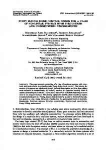
The designed static and dynamic sliding mode controllers are implemented using an experimental set-up depicted in ® gure 1. The system consists of a PM stepper motor, diŒerent loads to be attached to the shaft of the motor, drive circuitry, two current sensors, an optical encoder and a controller board. The two controllers are implemented using a digital signal processor (DSP). The algorithms for the two controllers are written as C programs and then compiled into assembly codes. These codes are then downloaded into the DSP (which resides on a controller board) from the computer. The block diagram representation of the overall system is shown in ® gure 2. The motor used in the implementation is a unipolar hybrid permanent magnet stepper motor (Vexta, model PH268-22B). The motor has a shaft at both of its ends. Therefore, the attachment of diŒerent loads and an optical encoder to the shaft is simple. A driver circuit is required to interface between the controller board and the PM stepper motor. This is the case because the peripheral sub-systems of the controller board have very low current capabilities. An optical encoder is used to
110
M. Zribi et al.
Downloaded by [Kuwait University] at 22:52 09 November 2014
Figure 2.
Block diagram of the overall system.
measure the position of the PM stepper motor shaft. Two current sensors are also used to measure the currents supplied to the two coils of the PM stepper motor. The measured data is then fed back to the controller board for processing. An observer is used to estimate the angular velocity of the shaft of the motor; see the work of Chiasson and Novotnal (1993). The brain of the system is a digital signal processor (the DS1102 ¯ oating point processor board which is based on Texas Instrument TMS320C31 ¯ oating point Digital Signal Processor). The parameters of the system are needed for implementation purposes. The least square estimation technique (see Blauch et al. 1993) was used to estimate the motor torque constant, the inertia constant and the coe cient of viscous friction. The other parameters are either measurable or are supplied by the manufacturer. It is found that these parameters are such: R ˆ 19:1388 «, L ˆ 40 mH, Km ˆ 0:1349 Nm=A, J ˆ 4:1295 £ 10 ¡4 kg m2 , B ˆ 0:0013 Nm=rad=s and Nr ˆ 50. The objective of the implementation is for the shaft of the motor to rotate by one step (one step ˆ 1:88 ˆ 0:031 42 radians) as fast as possible and with the least amount of overshoot (critically damped response). Such a behaviour is a typical representation of fast and accurate positioning for robotic applications. To simulate the diŒerent loads experienced by the stepper motor, diŒerent weights are attached to the shaft of the motor by an extension arm of about 6 cm. It is found that the maximum load the motor can drive is 1060 g. For this implementation, several loads are used to simulate diŒerent loads on the motor. The results shown in this paper correspond to loads of 105 g and 880 g. The design parameters for the static controller are chosen such that W1 ˆ 1000, W2 ˆ 7 £ 105 , ¬1 ˆ 550 and ¬2 ˆ 7:5 £ 104 . The design parameters for the dynamic controller are chosen such that W10 ˆ 2000, W20 ˆ 5:5 £ 107 , ¶ 0 ˆ 480 and ¬10 ˆ 1250, ¬20 ˆ 47 £ 104 , ¬30 ˆ 5:2 £ 107 . Obviously the choice of these parameters is not unique. However, because of the hardware limitations and the required speci® cations the parameters have been chosen as given above. The implementation results are given in ® gures 3± 6. It can be seen from the ® gures that the state variables
converge towards their corresponding equilibrium points when the static and the dynamic sliding mode control schemes are used. Figures 3 and 5 depict the implementation results when the static sliding mode controller is used with loads of 105 g and 880 g. It can been seen from these two ® gures that the angular position of the shaft of the motor converges towards its desired value …1:88 ˆ 0:031 42 radians† in less than 0.1 s when the load is 105 g and in less than 0.2 s when the load is 880 g. As expected, the settling time is longer for heavier loads. In addition, the response of the angular position of the shaft of the motor is critically damped in both cases. The currents in coils A and B, the voltages va , vb , as well as the sliding surfaces are also shown in ® gures 3 and 5. It should be noted that because of the hardware constraints, the input voltages va and vb are restricted to the range of 0± 12 V. The control inputs va and vb are seen to exhibit a discontinuous behaviour of the bang-bang type caused by the existence, in ® nite time, of a sliding regime on the intersection of the proposed stabilizing sliding surfaces s1 ˆ 0 and s2 ˆ 0. The controlled angular position trajectory x4 , is seen to be quite smooth, due to the fact that a third order integration separates the bang-bang control input u2 from the angular position x4 . However, chattering is quite strong on the regulated motor currents, since only one order of integration separates the bang-bang control input u1 from the regulated variable x1 . Figures 4 and 6 depict the implementation results when the dynamic sliding mode controller is used with loads of 105 g and 880 g. It can be seen from these two ® gures that the angular position of the shaft of the motor converges towards its desired value …1:88 ˆ 0:031 42 radians† in less than 0.15 s when the load is 105 g and in less than 0.2 s when the load is 880 g. In addition, the response of the angular position of the shaft of the motor is critically damped in both cases. The currents in coils A and B, the voltages va , vb , as well as the sliding surfaces are shown in ® gures 4 and 6. The control inputs va and vb , the currents and the sliding surfaces are seen to exhibit substantially less chattering than in the static sliding mode control case. Note that all the state variables asymptotically converge to the desired equilibrium points. The responses of the angular position of the shaft of the motor when the static and dynamic sliding mode controllers are used are depicted in the same plot; the
Downloaded by [Kuwait University] at 22:52 09 November 2014
Control schemes for a PM stepper motor
111
(a)
(b) Figure 3.
(a) Actual responses of the motor when the static sliding mode controller is used (with a load of 105 g). (b) Actual switching surfaces and actual static sliding mode controllers (with a load of 105 g).
Downloaded by [Kuwait University] at 22:52 09 November 2014
112
M. Zribi et al.
(a)
(b) Figure 4.
(a) Actual responses of the motor when the dynamic sliding mode controller is used (with a load of 105 g). (b) Actual switching surfaces and actual dynamic sliding mode controllers (with a load of 105 g).
Downloaded by [Kuwait University] at 22:52 09 November 2014
Control schemes for a PM stepper motor
113
(a)
(b) Figure 5.
(a) Actual responses of the motor when the static sliding mode controller is used (with a load of 880 g). (b) Actual switching surfaces and actual static sliding mode controllers (with a load of 880 g).
Downloaded by [Kuwait University] at 22:52 09 November 2014
114
M. Zribi et al.
(a)
(b) Figure 6.
(a) Actual responses of the motor when the dynamic sliding mode controller is used (with a load of 880 g). (b) Actual switching surfaces and actual dynamic sliding mode controllers (with a load of 880 g).
Downloaded by [Kuwait University] at 22:52 09 November 2014
Control schemes for a PM stepper motor
Figure 7.
Comparison of the responses of angular position of the shaft of the motor with load of 105 g.
Figure 8.
Comparison of the responses of angular position of the shaft of the motor with load of 880 g.
115
116
M. Zribi et al.
open loop response is also shown in that plot. Figure 7 shows the plots when the load is 105 g; ® gure 8 shows the plots when the load is 880 g. From these two ® gures, it can been seen that closed loop plots are far superior to the open loop plots. In addition, the response of the shaft of the motor, when the dynamic sliding mode controller is used, is slightly better than the one when the static sliding mode controller is used. In summary, it can be concluded that the closed loop operation of the PM stepper motor system with the static and the dynamic sliding mode controllers is found to be working very well under diŒerent loading conditions.
Downloaded by [Kuwait University] at 22:52 09 November 2014
6.
Conclusion
In this article we have used multivariable sliding mode controllers to control a PM stepper motor. Sliding mode controller design is shown to be greatly facilitated by resorting to the diŒerential ¯ atness of the system. The method presented constitutes a systematic means of sliding mode controller design, which largely solves the problem of obtaining de-coupled linearizing sliding modes. At the same time the approach is quite permeable to dynamic extensions of the system. This fact and the ¯ atness of the system naturally results in the possibilities of proposing dynamic multivariable sliding mode controllers for non-linear controllable systems. An added bonus of resorting to the ¯ atness of the system is the fact that the obtained sliding mode controllers are entirely endogenous. Implementation results of the developed controllers on an experimental setup illustrate the developed theory. References A IELLO, M ., R EKOWSKI, R ., BODSON, M ., C HIASSON, J ., and SCHUERER , D ., 1991, Experimental results of parameter identi® cation and nonlinear control of a PM stepper motor. In S. G. Tzafestas (Ed.) Microprocessors in Robotic and Manufacturing Systems (Amsterdam: Kluwer Academic Publishers), pp. 353± 368. BARTOLINI, G ., and Z OLEZZI, T ., 1986, Control of nonlinear variable structure systems. Journal of Mathematical Analysis and Applications, 118, 42± 62. BLAUCH, A . J ., BODSON, M ., and C HIASSON, J ., 1993, Highspeed parameter estimation of stepper motors. IEEE Transactions on Control Systems Technology, 1, 270± 279. BODSON, M ., and C HIASSON, J ., 1989, Application of nonlinear control methods to the positioning of a permanent magnet stepper motor. Proceedings of the 28th Conference on Decision and Control, Austin, Texas, USA, pp. 531± 532. BODSON, M ., C HIASSON, J ., N OVOTNAK, R ., and R EKOWSKI, R ., 1993, High-performance nonlinear feedback control of a permanent magnet stepper motor. IEEE Transactions on Control Systems Technology, 1, 5± 14. BURG, T ., H U, J ., D AWSON , D . M ., and VEDAGARBHA, P ., 1994, A global exponential position tracking controller for a permanent magnet stepper motor via output feedback. Proceedings of the 3rd IEEE Conference on Control Applications, Glasgow, Scotland, pp. 213± 218.
C HELOUAH, A ., D ELALEAU, E ., M ARTIN, P ., and R OUCHON, P ., 1996, DiŒerential ¯ atness and control of induction motors. Proceedings of the Symposium on Control, Optimization and SupervisionÐ Computational Engineering in Systems Applications, IMACS Multi-conference, Lille, France, pp. 80± 85. C HIASSON, J ., and N OVOTNAL, R . T ., 1993, Nonlinear speed observer for the PM stepper motor. IEEE Transactions on Automatic Control, 38, 1584± 1588. D ECARLO, R ., Z AK, S., and M ATHEWS, G ., 1988, Variable structure of nonlinear multivariable systems: a tutorial. Proceedings of the IEEE, 76, 212± 232. E L-G HEZAWI, O . M . E ., Z INOBER, A . S. I ., and BILLINGS, S. A ., 1983, Analysis and design of variable structure systems using a geometric approach. International Journal of Control, 38, 657± 671. E MELYANOV, S. V., 1967, Variable Structure Control Systems (Moscow: Nauka). F LIESS, M ., and SIRA-R AMIREZ , H ., 1993, A module theoretic approach to sliding mode control of linear systems. Proceedings of the IEEE Conference on Decision and Control, San Antonio, Texas, USA, pp. 1322± 1323. F LIESS, M ., L EVINE, J ., M ARTIN, P ., and R OUCHON, P ., 1992 a, Sur les systemes lineaires diŒerentiellement plats. C. R. Acad. Sci. Paris, 316, 619± 624. F LIESS, M ., L EVINE, J ., M ARTIN, P ., and R OUCHON, P ., 1992 b, On diŒerentially ¯ at nonlinear systems. In M. Fliess (Ed.) Nonlinear Control Systems Design (Oxford: Pergamon Press), pp. 408± 412. F LIESS, M ., L EVINE, J ., M ARTIN, P ., and R OUCHON, P ., 1995, Flatness and defect of nonlinear systems: Introductory theory and examples. International Journal of Control, 61, 1327± 1362. I TKIS, Y ., 1978, Control Systems of Variable Structure (New York: Wiley). K ENJO, T ., and SUGAWARA, A ., 1994, Stepping Motors and their Microprocessor Controls, Second Edition (Oxford: Clarendon Press). K WATNY, H ., and K IM, H ., 1990, Variable structure regulations of partially linearizable dynamics. Systems and Control Letters, 15, 67± 79. L EVINE, J ., L OTTIN, J ., and P ONSART, J . C ., 1996, A nonlinear approach to the control of magnetic bearings. IEEE transactions on Control Systems Technology, 4, 524± 544. M ARTIN, P ., and R OUCHON, P ., 1996, Flatness and sampling control of induction motors. Proceedings of the 13th Triennial World Congress, San Francisco, California, USA, pp. 389± 394. P OMET , J . B., M OOG, C . H ., and A RANDA-BRICAIRE, E ., 1992, A non-exact Brunovsky form and dynamic feedback linearization. Proceedings of the IEEE Conference on Decision and Control, Tucson, Arizona, USA, pp. 2012± 2017. R OTHFUSS, R ., R UDOLPH, J ., and Z EITZ , M ., 1996, Flatness based control of a nonlinear chemical reactor. Automatica, 32, 1433± 1439. SIRA-R AMIREZ , H ., 1988, DiŒerential geometric methods in variable structure control. International Journal of Control, 48, 1359± 1391. SIRA-R AMIREZ , H ., 1996, On the sliding mode control of multivariable nonlinear systems. International Journal of Control, 64, 745± 765. SIRA-R AMIREZ , H ., Z RIBI, M ., and A HMAD, A ., 1994, Dynamical sliding mode control approach for vertical ¯ ight regulation in helicopters. IEE proceedings Control Theory and Applications, 141, 19± 24.
Downloaded by [Kuwait University] at 22:52 09 November 2014
Control schemes for a PM stepper motor
117
SLOTINE, J .-J ., and L I, W ., 1991, Applied Nonlinear Control
U TKIN, V. I ., and Y OUNG, K . K . D ., 1978, Methods of con-
(New Jersey: Prentice Hall). SLOTINE, J . J . E ., and SASTRY, S. S., 1983, Tracking control of nonlinear systems using sliding surfaces with applications to robot manipulators. International Journal of Control, 38, 465± 492. SPEAGLE, R . C ., and D AWSON, D . M ., 1993, Adaptive tracking control of a permanent magnet stepper motor driving a mechanical load. Proceedings of the IEEE Southeastcon, Charlotte, North Carolina, USA, pp. 115± 119. SPEAGLE, R . C ., H U, J ., D AWSON, D . M ., and QU , Z ., 1993, Robust control of a permanent magnet stepper motor without current measurements. Proceedings of the 2nd IEEE Conference on Control Applications, Vancouver, Canada, pp. 153± 158. U TKIN, V. I ., 1978, Sliding Modes and Their Applications in Variable Structure Systems (Moscow: MIR). U TKIN, V. I ., 1992, Sliding Modes in Control and Optimization (Berlin: Springer-Verlag).
structing discontinuity planes in multidimensional variable structure systems. Automation and Remote Control, 39, 1466± 1470. Y OUNG, K . K . D ., 1978, Controller design for a manipulator using the theory of variable structure systems. IEEE Transactions on Systems, Man and Cybernetics, 8, 101± 109. Y OUNG, K . K . D ., U TKIN, V. I ., and O ZGUNER, U ., 1999, A control engineer’s guide to sliding mode control. IEEE Transactions on Control, Systems Technology, 7, 328± 342. Z INOBER, A . S. I ., 1994, Variable structure and Lyapunov control. Lecture Notes in Control and Information Sciences, 193 (New York: Springer-Verlag). Z RIBI, M ., and C HIASSON, J ., 1991, Position control of a PM stepper motor by exact linearization. IEEE Transactions on Automatic Control, 36, 620± 625.