6th International Conference on Electrical and Computer Engineering ICECE 2010, 18-20 December 2010, Dhaka, Bangladesh
Steady State Characteristic Simulation of DFIG for Wind Power System Md. Rabiul Islam1, Youguang Guo, Jian Guo Zhu Faculty of Engineering and Information Technology, University of Technology Sydney, Australia 1 E-mail:
[email protected],
[email protected]
Abstract— Wind power, as an important and promising renewable resource, is widely studied. Because the wind is highly variable, it is very desirable to operate a wind turbine at variable speeds. In this respect, doubly fed induction generator (DFIG) has become popular in wind power generation system. The steady state simulation analysis of a DFIG is essential to understand the behavior of DFIG such that it can operate at maximum power producing point for a given wind speed. This paper explores the steady state characteristic of a DFIG in wind power generation system using MATLAB. Keywords— Wind power, DFIG, steady state characteristic, simulation
Fig. 1 Basic block diagram of DFIG system
978-1-4244-6279-7/10/$26.00 ©2010 IEEE
II. WIND POWER MODEL Wind turbine converts the wind energy to electricity energy and it follows the energy conservation principle. Let A be the cross-sectional area through which the air flows at the velocity of V and P is the power. The theoretical power available in a wind stream is given by [4].
P=
1 ρAV 3 (W) 2
(1)
where ρ is the air mass density (kg/m3) The wind turbine is required to operate within its maximum allowable limits of speed and power. The characteristic of P versus V is illustrated in Fig. 2. When V is larger than 20 m/s, the wind turbine reaches its rated power. 4
5
x 10
4.5 4 3.5 Wind power
I. INTRODUCTION Two major global crises that mankind is facing currently, are the energy crisis and the environment or climate crisis. It is becoming more and more obvious that wind energy may offer solutions to these enormous challenges. Wind energy has continued the worldwide success story as the wind power development is experiencing dramatic growth. According to the World Wind Energy Association (WWEA), the global wind installations reached 121,188 MW in 2008, after 59,024 MW in 2005, 74,151 MW in 2006, and 93,927 MW in 2007 [1]. Globally installed capacity growth has doubled every two to three years. Wind power is now being deployed in over 70 countries around the world [2]. The dynamic growth of wind power directly pushes the wind technology into a more competitive area. It is essential for scientists and researchers to find out the effective technologies for the wind power generation system. The wind speed varies continuously as a function of time and height because of change in the thermal conditions of air masses. The motion of air masses is not only a global phenomenon but also a regional and local phenomenon. Because the wind is highly variable, it is very desirable to operate a wind turbine at variable speeds. With variable speeds the turbine is able to operate at its maximum power producing point for a given wind speed. The variable speed wind turbine with a DFIG, and partially rated power converter (approximately 30% of generator power) on the rotor circuit as shown in Fig. 1 are well-matched for the above needs. The stator is directly connected to the grid, while a partially rated power converter is used to control the rotor frequency as well as rotor speed. The partially rated converter performs the reactive power compensation and the smoother grid connection. This system can not only increase energy transfer efficiency and decreasing mechanical stress, but also can achieve the decoupling control of generator active and reactive power [3].
3 2.5 2 1.5
Cut in
Rated speed
1 0.5 0
0
5
10
15
20
25
Wind speed
Fig. 2 Characteristic of wind power with the variation of wind speed
Actual power produced by the machine, PT would be determined by the efficiency with which the energy is transferred. The efficiency is usually termed as the power coefficient CP, so the theoretical power that can be extracted from the wind is
151
PT =
1 ρAV 3 C P 2
(2)
In practical case there is a limitation of maximum rotor torque. If CT is the torque coefficient, the actual torque developed by the rotor TT is (3) TT = TCT The ratio between the velocity of the rotor tip and the wind velocity is the tip speed ratio which is defined by
λ=
RΩ V
(4)
where Ω is the angular velocity of the rotor. By putting the value PT = TT Ω and using (2) to (4) we have CP/CT = λ The power coefficient also can be expressed as a function of tip speed ratio λ and the pitch angle θ as [5]
⎛ 116 ⎞ C p (λ , θ ) = 0.22⎜⎜ − 0.4θ − 5 ⎟⎟e ⎝ λi ⎠ where
λi can
Fig. 4 Principle of DFIG
−12.5
λi
(5)
V1
also be approximated by a function of the tip
speed ratio and the pitch angle
λi =
(θ
)
θ , as
+ 1 (λ + 0.08θ ) θ + 1 − 0.035(λ + 0.08θ ) 3
3
Fig. 5 T-type per phase equivalent circuit of DFIG
(6)
The characteristic of power coefficient versus tip speed is shown in Fig. 3. Under a certain V the wind power can be controlled by adjusting either tip speed ratio or pitch angle.
+ j
0.45 0.4
I2 =
Power coefficient
0.35 0.3
0.2 0.15 0.1 0.05 0
2
4
6 Tip speed ratio
8
10
12
Fig. 3 Characteristic of power coefficient with the variation of tip speed ratio
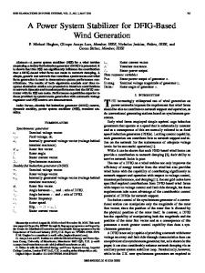
III. DFIG EQUIVALENT CIRCUIT It is based on an induction generator with a multiphase wound rotor and a multiphase slip ring assembly with brushes for access to the rotor windings. The principle of the DFIG is that rotor windings are connected to the grid via slip rings and a converter controls both the rotor and the grid currents. Thus rotor frequency can freely differ from the grid frequency. The speed of the generator will vary with the turning force applied to its rotor. The difference between this speed and the synchronous speed in per cent is called the generator’s slip, which sets the frequency of the generated voltage [6]. The schematic diagram of DFIG is shown in Fig. 4 [7]. The per-phase equivalent circuit of the DFIG is shown in Fig. 5. IV. DFIG MODEL EQUATIONS When a mechanical torque is applied to the rotor shaft of DFIG, the rotor rotates with an angular speed ωm which corresponds to a slip s = (ω-ωm)/ω where ω is the synchronous speed. If α is the angle between stator and rotor applied voltages, the stator and rotor currents are [8]
V 1 [ Da {V1 ( x 2 + x f ) − x f 2 cos α } − D s V2 r x f sin α + V 1 2 )] − Db ( s s
(7)
1 V [ Da 2 (r2 cos α − ( x2 + x f ) sin α ) + D s
V + Db { 2 (cos α ( x 2 + x f ) + r1 sin α ) − V1 x f }] s V 1 + j [ Da ( 2 (( x1 + x f ) cosα + r1 sin α ) − V1 x f ))] − D s V 1 − j [ Db 2 {r1 cos α − ( x1 + x f ) sin α }] D s rr where Da = [ 1 2 − ( x1 x 2 + x f ( x1 + x 2 ))] s r r Db = [ r1 x 2 + 2 x1 + x f ( r1 + 2 )] s s and D = Da2 + Db2
0.25
0
I2
I1
(8)
The power delivered from the mains to the stator can be *
derived from P1 = Re (V 1 .I 1 ) i.e.
P1 =
V12 r2 x [ r1 22 + r1 ( x 2 + x f ) 2 + x 2f 2 ] − D s s V1V2 − x f [cos α ( Db − sin α ( Da )] sD
(9)
The stator reactive power can be derived by using the relation *
Q1 = I m (V 1 .I 1 ) as
1 V r V I1 = [Da ( 2 xf sinα +V1 2 ) + Db{V1(x2 + xf ) − xf 2 cosα}+ D s s s 152
Q1 = +
V1V2 x f [cosα (Da ) + sinα (Db )]+ Ds
V12 [( x 2 + x f ){x1 x 2 + x f ( x1 + x 2 )} + D r2 + 22 ( x1 + x f )] s
(10)
The power delivered to the rotor by the excitation source can be expressed in terms of equivalent circuit parameters is The real power P2 = Re[(
=
* V2 )(cos α + j sin α ) I 2 ] s
V22 rr r r r [r1 1 2 + ( x1 + x f ) 2 x1 + x f ( x1 2 + x f (r1 + 2 ))]− 2 s s s s s D
injected voltage magnitude. Fig. 10 shows the stator reactive power characteristics of DFIG as the variation of rotor voltage magnitude while α is kept constant. The variation of stator reactive power with respect of injected rotor voltage is shown in Fig. 11 where α and slip are constant. 4
3
V1V2 x f {cosα ( Db ) + sin α ( Da )} (11) sD * V The reactive power Q2 = I m [ 2 (cos α + j sin α ) I 2 ] s V Q2 = 2 2 [( x2 + x f )r12 + ( x1 + x f )( x1 x2 + x f ( x1 + x2 ))] + s D VV + 1 2 x f [cos α ( Da ) − sin α ( Db )] (12) sD
700 2 600
Stator real power
1.5 1 0.5 0 -0.5 -1 -1.5
The electromagnetic torque may be derived from the developed mechanical power and the synchronous speed.
Pm
ωm
=−
-2 -1
[cos α {
0 Slip
0.2
0.4
0.6
0.8
1
x 10
100 V 80 V
0
)−
r2 ( x1 + x f ) − r1 ( x 2 + x f )} + s
sDω rr + sin α { 1 2 + x1 x2 + x f ( x1 + x2 )}] s
-0.2
120 V
Stator real power
3V1V2 x f
s
-0.4
1
-1 -2 -3 -4
(13)
-5
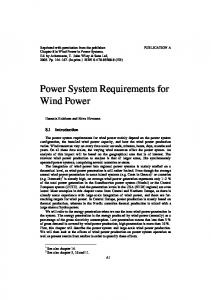
V. SIMULATION RESULTS & DISCUSSION An effective way to understand the operating characteristics of a DFIG is to investigate DFIG characteristic curves through computer simulation. Unlike a traditional induction machine, these characteristics not only depend on the applied stator voltage, but also depend on the injected rotor voltage V2. A conventional fixed-speed induction machine operates in generating mode for - 1 < s ≤ 0 and motoring mode for 0 < s ≤ 1 . DFIG can run at both over and below synchronous speed to generate electricity. The generating mode of DFIG corresponding to negative torque values extends from the negative slip to positive slip region. Hence, the turbine output power and electromagnetic torque characteristics of DFIGs are different from traditional fixedspeed induction machine. The stator real and reactive power can be modified by varying the amplitude and phase angle of the equivalent injected rotor voltage. Fig. 6 shows the DFIG stator real power as variation in α while the rotor injected voltage magnitude is kept constant at 80 V and Fig. 7 shows the stator real power variation against rotor injected voltage magnitude while α is kept constant at 300. Fig. 8 shows the injected rotor voltage magnitude versus stator real power when both slip and α are fixed. A traditional induction machine takes inductive reactive power from the power supply system that its leakage and magnetizing reactive power needs under both generating and motoring modes. It is different for a DFIG due to the injected rotor voltage. The variation of stator reactive power as the variation of α while voltage magnitude remains constant is shown in Fig. 9. The stator reactive power also changes with the variation of rotor
-6 -1
-0.8
-0.6
-0.4
-0.2
0 Slip
0.2
0.4
0.6
0.8
1
Fig. 7 Slip versus real power of the stator for different value of rotor voltage
153
5000
4800 s=0.12 Stator real power
−
ωDs
(x f V r −
x f V22 r1
-0.6
4
2
4600
s=0.11 s=0.1
4400
4200
4000
3800 10
11
12
13
14 15 Rotor voltage
16
17
18
Fig. 8 Rotor voltage versus stator real power for different value of slip 4
0.5
x 10
0 1800 Stator reactive power
T=
2 1 2
-0.8
Fig. 6 Slip versus real power delivered from mains to the stator for different values of α.
Pm ω (1 − s )
By using equivalent circuit parameters the electromagnetic torque can be expressed as
3x f
800
2.5
−
T=
x 10
1600
-0.5
1400 -1
-1.5
-2
-2.5 -1
-0.8
-0.6
-0.4
-0.2
0 Slip
0.2
0.4
0.6
0.8
1
Fig. 9 Slip versus reactive power of the stator for different value of α
4
4
2
x 10
1
x 10
40 V 0
0
Dev eloped torque
Stator reactive power
-2 80 V 100 V -4 120 V -6
-1
30 V
-2 20 V -3
-8
-4 -10
-5 -1 -12 -1
-0.8
-0.6
-0.4
-0.2
0 Slip
0.2
0.4
0.6
0.8
1
-0.8
-0.6
-0.4
-0.2
0 Slip
0.2
0.4
0.6
0.8
1
Fig. 13 Slip versus developed torque of DFIG for different values of rotor voltage
Fig. 10 Slip versus reactive power of the stator for different value of rotor voltage
The variations of developed torque of DFIG with respect to injected rotor voltage are shown in Fig. 14 where slip and α are fixed.
-200 -250
7000
s=-0.6
-300
6000 s=-0.5
5000
-400
4000 Developed torque
Stator reactive power
s=-0.55 -350
-450 -500 -550
3000 s=-0.1
s=-0.2
s=-0.3
2000 1000
-600
0 -650 10
11
12
13
14 15 Rotor voltage
16
17
18
-1000
Fig. 11 Rotor voltage versus stator reactive power for different value of slip
-2000 15
The simulation results of torque-speed are shown in Figs. 12 and 13. Unlike a traditional induction machine, these characteristics not only depend on the applied stator voltage, but also depend on the injected rotor voltage.
8000
1600
[2]
Developed torque
1700 4000
[3] 2000 1800 0
-2000
-6000 -1
[4] -0.8
-0.6
-0.4
-0.2
0 Slip
0.2
0.4
0.6
0.8
[5]
1
Fig. 12 Slip versus developed torque of DFIG for different values of α
VI. CONCLUSIONS In this paper a simulation analysis on the operating characteristics of a DFIG is carried out. Stator and rotor real and reactive power as well as electromagnetic torque are analyzed as functions of the slip, the rotor injected voltage and the angle α. From the simulation results it is clear that the characteristics of DFIG are affected by its injected rotor voltage.
18
19 20 21 Rotor voltage
22
23
24
25
REFERENCES
6000
-4000
17
Fig. 14 Rotor voltage versus developed torque of DFIG for different value of slip
[1]
10000
16
[6] [7] [8]
154
World Wind Energy Report 2008, World Wind Energy Association (2009). [Online]. Available: http://www.wwindea. org/home/images/stories/worldwindenergyreport2008_s.pdf Denmark-Wind Power HUB, Profile of the Danish Wind Industry, Danish Wind Industry Association. [Online]. Available: http://www.windpower.org/download/378/ profilbrochure_2008.pdf M. Aktarujjaman, M. E. Haque, K. M. Muttaqi, M. Negnevitsky, and G. Ledwich, “Control dynamics of a doubly fed induction generator under sub- and super-synchronous modes of operation,” Power and Energy Society General Meeting – Conversion and Delivery of Electrical Energy in the 21st Century, IEEE , pp. 1- 9, 2009. Z. Du and W. Gu, “Aerodynamics analysis of wind power,” World Non-Grid-Connected Wind Power and Energy Conference, IEEE - Xplore, pp. 1-3, 24-26 September 2009. J. Ning, W. Gao, and J. Ojo, “Decoupled control of doubly fed induction generator for wind power system,” Power Symposium, 2008. 40th North American , IEEE - Xplore, pp. 1-6, 28-30 Sept. 2008 L. L. Lai and T. F. Chan, “Distributed generation,” IEEE Press, John Wiley & Sons Ltd, 2007. A. Petersson, “Analysis, Modeling and control of doubly-fed induction generators for wind turbines,” PhD Dissertation, Chalmers University of Technology, Sweden, 2005. M. S. Vicatos and J. A. Ieqopoulos, “Steady state analysis of a doubly fed induction generator under synchronous operation,” IEEE Transactions on Energy Conversion, vol. 4, no. 3, pp. 495-501, 1989.