Stealth-Based Path Planning using Corridor Maps Roland Geraerts and Erik Schager Institute of Information and Computing Sciences, Utrecht University 3508 TA Utrecht, the Netherlands
[email protected];
[email protected]
Abstract A relatively new area within the field of path planning deals with computing a stealthy path for a character moving in a virtual environment. Besides efficiently obtaining a path that is collision-free, short and smooth, the added difficulty is that the path must have little or no exposure to observers. We propose a new algorithm for computing such a path in the plane, and show that real-time performance can be achieved. Keywords: path planning, 2D-visibility
stealthy path,
1 Introduction Virtual environments are commonly used in computer games, simulations and training applications. In such environments, characters often have to find a collision-free path between a start and goal position. The general path planning problem has been studied extensively in the fields of robotics [7] and games [4, 10]. A relatively new problem is finding such a path while avoiding being detected by an observer. The observer can be stationary, such as a surveillance camera which sweeps the environment for detecting unwanted persons, or movable, such as a hostile person. An entity such as a human, robot or vehicle, needs to minimize its exposure to the observer, e.g. during a military operation [1, 8, 11, 15]. Also in games, non-player characters may need to stay hidden from the enemy, minimize exposure to enemy fire, or take cover and shoot from covered positions to create believable game-play [3, 12, 14]. These application areas can be categorized as covert navigation or stealth-based path planning and they will be the focus of this paper. Stealth-based path planning techniques usually employ a three-step approach to create a path with little or no exposure. In virtual environment applications, there is only little CPU time available for executing these steps, es-
Fig. 1: A smooth, stealthy path for a character who tries to minimize its exposure to the (red) observers.
pecially when many (dynamic) observers are present. Hence, they must be carried out efficiently. To allow real-time computations, we limit ourselves to path planning in the plane. In the first step, a collision map of the environment is created. The map is a twodimensional grid of cells where each cell is labeled either occupied with an obstacle or free. We assume that the (polygonal) environment is known [5, 12], and, hence, the map can be created easily, e.g. by using GPU-accelerated rasterization techniques [13]. In the second step, a visibility map is computed where each free cell is associated with a visibility value. This value describes how many observers can see (the center point of) this cell, and how well they can see it. In the third step, a stealthy path is computed from the map. Such a path usually has minimum exposure (i.e. the sum of visibility values along the path is minimized), minimum length, or is reasonably short and has little exposure. Our new algorithm uses the Corridor Map data structure [9], which represents a planar subdivision of the environment, and, hence, implicitly encodes the collision map. We show how this structure can be used to compute visibility polygons. Next, we extend this structure such that stealthy paths can be computed efficiently.
The paper is organized as follows. In Sections 2 and 3 we discuss the visibility and planning method. Then, we conduct experiments in Section 4 and conclude in Section 5 that our method computes high-quality stealthy paths without compromising real-time performance.
2 Visibility algorithm Much research has already been done on computing 2D- and 3D-visibility. An excellent survey can be found here [2]. In our paper, we limit ourselves to computing visibility of a point in the plane to enable real-time computations. We use the Corridor Map-data structure [9] to compute visibility polygons. An example of this structure is visualized in Fig. 4(a). It forms a planar subdivision of the free space in an environment and is created as follows. First, the generalized Voronoi diagram (red curves) is computed using graphics hardware. The diagram consists of nodes (large black disks) and edges (red curves) between pairs of nodes. These edges are sampled, and with each sample (black disks), its left and right closest point (black lines) on the obstacles is stored. Given this representation, the visibility polygon is computed, as follows. First the closest sample s to the observer is found by querying a KD-tree that indexes the Corridor Map. Next, two visibility cones are constructed. Each cone originates from the observer’s location and its sides correspond to the closest points of s. Next, we walk along both directions of the corresponding edge while updating each cone based on the closest points’ positions. When a node is visited we recursively walk along its incident edges. The process stops when the visibility cone is empty. The visibility polygon’s vertices are then given by the visited closest points. Pseudo-code on this procedure can be found in reference [13]. Fig. 2 shows such a polygon, together with the visited closest points (disks) on the obstacles. We expect this algorithm to be efficient, since it is output sensitive. We have implicitly assumed that an observer has non-decreasing vision over an infinite range with a 360 degree field of view (FOV). We obtain a more realistic vision model by limiting these aspects. This model can be realized efficiently by using graphics hardware. We model the observer’s FOV as a partial disk, approximated by a triangle fan. The larger the number of triangles, the more accurate the approximation becomes. To limit the observer’s
Fig. 2: The visibility polygon computed by our algorithm. The red disk denotes the observer’s location and the white area denotes its visible area.
A B
C
D
Fig. 3: A more realistic vision model, integrated in a visibility map: (A) limited range, (B) limited field of view, (C) decreasing visibility, (D) additive blending.
vision, we specify a visibility value at its location and one at the far end of its FOV. Then we let the visibility change linearly from the first to the second value. Such a (partial) disk can be created efficiently by using graphics hardware. We refer the reader to Fig. 3 which displays the more realistic vision model. Note that different visibility polygons can be blended into a single visibility map, again by using the GPU.
3 Planning algorithm The visibility map forms the input for our stealthy path planning method. We could directly use this map to plan a stealthy path, e.g. by running the A*-algorithm [16] on this map. We expect this method to be fast, except for large environments or for environments that have a maze-like structure. In addition, the running times of this method would heavily depend on the resolution of the map. Also, narrow passages or small obstacles might not be noticed in a low-resolution map. We designed a new method, based on the Corridor Map (CM) data structure, to approach these shortcomings. The CM is a sparse graph so an A*-search on this graph will be fast compared to running an A*-search on the visibility map.
However, paths extracted from the CM might be longer than necessary and might not provide enough cover since its Voronoi edges have a maximum clearance. To facilitate high-quality stealthy paths, we add ‘useful’ edges to the CM and refer to this structure as the CMPlus graph. Fig. 4(b) shows such a graph. In the graph, we add an edge between two adjacent left closest points and an edge between two adjacent right closest points. These edges run close to obstacles, providing cover of the entity. Next, we add diagonal connections between a sample and the two closest points of its adjacent samples if they cover at least a certain minimum distance, and, therefore, add significantly to the possible routes that can be taken. However, to keep the graph small, we do not add edges at samples having a small clearance. A stealthy path, such as the one displayed in Fig. 1, is now retrieved as follows. Our method uses the A*-algorithm to find the shortest path in the CMPlus graph. The costs of an edge is its length multiplied with its average visibility, which is obtained by densely sampling the edge with visibility values from the map. Next, the Indicative Route Method [6] is used to smooth the path, to cut unnecessary corners, and to introduce a variable amount of minimum clearance to the path. Note that these properties are hard to obtain if we would directly apply the A*-algorithm on the visibility map. While a minimum-clearance path is more natural and avoids collisions with obstacles when the character is animated, it might be longer than a shortest path produced by running A* on the map.
4 Experiments We have conducted experiments with the visibility and planning algorithms. All the experiments were tested on one environment and were run on a PC with an NVIDIA GeForce 7600 GT graphics card and an Intel Core2 Duo E6300 processor (1.86 GHz) with 1 GB memory. Only one core was used. The application was implemented in Visual C++ under Windows XP. We have conducted experiments with the Military environment depicted in Fig. 5. This environment measured 200x200 meter and its footprint comprised 23 polygons. It had some buildings in the center which could provide cover. They were surrounded by open space in which the sight-lines were long. The preprocessing phase took 69ms for building the Corridor map (using 1000x1000 pixels) and the CMplus graph. This graph comprised 56 vertices, 70 edges and 838 samples on the edges.
(a) Corridor Map
(b) CMPlus graph
Fig. 4: The Corridor Map and its derived CMPlus graph for the Military environment.
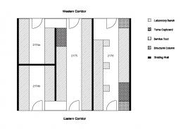
(a) Military environment
(b) Military footprint
Fig. 5: The Military environment and its footprint.
In all the experiments we used observers with 360 degrees field of view (FOV). Note however that a smaller FOV might have led to faster running times. We used a high visibility value (i.e. 128) at the observer’s location, and a low value (i.e. 0) at the end of its range. We represented the FOV with a triangle fan of at least 16 parts, which gave an accurate representation of a disk. We selected 100 uniform random queries consisting of one random location and a random visibility range, which we set between zero and the length of the environment’s diagonal. We ran each query at various resolutions, ranging from 200x200 to 1000x1000 pixels, while recording the average running times of the visibility algorithm. The experiments revealed running times ranging from 0.47ms at 200x200 to 4.65ms at 1000x1000. Consequently, the method is able to compute many visibility areas without sacrificing real-time performance at all resolutions. Next, we recorded the average running times of the planning algorithm at the mentioned resolutions. For each resolution, the algorithm was run 1000 times with three random observers. We kept only diagonal edges that were at least 8m in length and we used only closest points if there was at least 2m clearance, and, hence, they would make a significant difference for the possible routes. We sampled the edges with visibility values such that there was at least 1 sam-
ple per meter and at least 1 sample per edge. Preliminary experiments had shown that such sampling density was sufficient to detect significant changes in visibility. The experiments took, on average, 1.92ms at resolution 200x200 and 2.14ms at resolution 1000x1000, making our graph-based method marginally dependent on the resolution. In contrast, running A* on the visibility map at low resolutions would have ignored many narrow passages, and the clearance would have been low at some places, leading to possible collisions when the character would have been animated. The results showed that the path length and path’s visibility did not differ much across different resolutions, and, hence, a low resolution can be used for planning stealthy paths. Also, the method produced smooth paths having a desired amount of minimum clearance to the obstacles. Based on the low running times, we believe that our method is applicable to plan a path for a stealthy entity with many dynamic observers in real-time.
5 Conclusion We have introduced an algorithm for computing a stealthy path in the plane for a character moving in a virtual environment. Such a path had little or no exposure to one or more observers. Using the GPU and the Corridor Map data structure, we computed visibility polygons which were rendered into a visibility map. Each cell of the map described how many observers could see the cell and how well they could see it. Then, we computed a stealthy path through the visibility map by using a graph derived from the Corridor Map. The algorithm planned smooth, stealthy paths having a certain amount of minimum clearance to the obstacles and achieved real-time performance. In future work, we will compare our algorithm with existing algorithms that compute visibility areas and stealthy paths. In addition, we will concentrate on the dynamic nature of the problem. That is, we will include experiments with many dynamic observers. Also, by being able to dynamically update our graph when (large) obstacles move, the system allows for a fully dynamic solution that runs in real-time.
Acknowledgments This work was partially supported by the ITEA 2 Metaverse1 (www.metaverse1.org) Project.
References [1] E. Birgersson, A. Howard, and G. Sukhatme. Towards stealthy behaviors. In IEEE/RSJ International Conference on Intelligent Robots and Systems, pages 1703–1708, 2003. [2] D. Cohen-Or, Y. Chrysanthou, C. Silva, and F. Durand. A survey of visibility for walkthrough applications. IEEE Transactions on Visualization and Computer Graphics, 9:412– 431, 2003. [3] C. Darken. Visibility and concealment algorithms for 3d simulations. In Proceedings of Behavior Representation in Modeling and Simulation, 2004. [4] M. DeLoura. Game programming gems. Charles River Media, 2000. [5] R. Jarvis. Distance transform based visibility measures for covert path planning in known but dynamic environments. In International Conference on Autonomous Robots and Agents, pages 396–400, 2004. [6] I. Karamouzas, R. Geraerts, and M. Overmars. Indicative routes for path planning and crowd simulation. In The Fourth International Conference on the Foundations of Digital Games, pages 113–120, 2009. [7] S. LaValle. Planning Algorithms. Cambridge University Press, 2006. [8] M. Marzouqi and R. Jarvis. New visibilitybased path-planning approach for covert robotic navigation. Robotica, 24:759–773, 2006. [9] M. Overmars, I. Karamouzas, and R. Geraerts. Flexible path planning using corridor maps. In Algorithms – ESA, volume 5193 of Lecture Notes in Computer Science, pages 1–12. Springer, 2008. [10] S. Rabin. AI Game Programming Wisdom. Charles River Media, 2002. [11] S. Ravela, R. Weiss, B. Draper, B. Pinette, A. Hanson, and E. Riseman. Stealth navigation: Planning and behaviors. In Proceedings of ARPA Image Understanding Workshop, pages 1093–1100, 1994. [12] M. Rook and A. Kamphuis. Path finding using tactical information. In Poster proceedings of Eurographics/ACM SIGGRAPH Symposium on Computer Animation, pages 18–19, 2005. [13] E. Schager. Stealth-based path planning in virtual environments. Master’s thesis, Utrecht University, 2009. [14] R. Straatman, W. van der Sterren, and A. Beij. Killzone’s AI: dynamic procedural combat tactics. Gamasutra.com, 2005. [15] A. Tews, M. Matari´c, and G. Sukhatme. Avoiding detection in a dynamic environment. In IEEE/RSJ International Conference on Intelligent Robots and Systems, pages 134–138, 2004. [16] K. Trovato. A* Planning in Discrete Configuration Spaces of Autonomous Systems. PhD thesis, Universiteit van Amsterdam, 1996.