IEEE TRANSACTIONS ON ROBOTICS, VOL. 25, NO. 6, DECEMBER 2009
1343
Stereo Viewing and Virtual Reality Technologies in Mobile Robot Teleguide Salvatore Livatino, Giovanni Muscato, Senior Member, IEEE, and Filippo Privitera
Abstract—The use of 3-D stereoscopic visualization may provide a user with higher comprehension of remote environments in teleoperation when compared with 2-D viewing, in particular, a higher perception of environment depth characteristics, spatial localization, remote ambient layout, faster system learning, and decision performance. Works in the paper have demonstrated how stereo vision contributes to the improvement of the perception of some depth cues, often for abstract tasks, while it is hard to find works addressing stereoscopic visualization in mobile robot teleguide applications. This paper intends to contribute to this aspect by investigating the stereoscopic robot teleguide under different conditions, including typical navigation scenarios and the use of synthetic and real images. This paper also investigates how user performance may vary when employing different display technologies. Results from a set of test trials run on seven virtual reality systems, from laptop to large panorama and from head-mounted display to Cave automatic virtual environment (CAVE), emphasized few aspects that represent a base for further investigations as well as a guide when designing specific systems for telepresence. Index Terms—Stereo vision, teleoperation, telerobotics, 3-D displays, virtual reality.
I. INTRODUCTION HE 2-D display systems commonly used in robot teleoperation suffer from many limitations. Among them are misjudgment of self-motion and spatial localization, limited comprehension of remote ambient layout, object size and shape, etc. The above limitations lead to unwanted collisions during navigation, as well as long training periods for an operator. An advantageous alternative to traditional 2-D (monoscopic) visualization systems is represented by the use of a stereoscopic viewing. In the paper, we can find works demonstrating that stereoscopic visualization may provide a user with a higher sense of presence in remote environments because of higher depth perception, leading to higher comprehension of distance, as well as aspects related to it, e.g., ambient layout, obstacle perception, and the accuracy of manoeuvres [1]–[9]. The above conclusions can, in principle, be extended to teleguided robot navigation. However, it is hard to find works in the paper addressing the stereoscopic mobile robot teleguide. In
T
Manuscript received February 15, 2009. First published September 9, 2009; current version published December 8, 2009. This paper was recommended for publication by Associate Editor P. Rives and Editor F. Park upon evaluation of the reviewers’ comments. S. Livatino is with the School of Engineering and Technology, University of Hertfordshire, Hatfield AL10 9AB, U.K. (e-mail:
[email protected]). G. Muscato is with the Dipartimento di Ingegneria Elettrica Elettronica e dei Sistemi, University of Catania, Catania 95125, Italy (e-mail:
[email protected]). F. Privitera is with the Scuola Superiore di Catania, Catania 95125, Italy (e-mail:
[email protected]). Color versions of one or more of the figures in this paper are available online at http://ieeexplore.ieee.org. Digital Object Identifier 10.1109/TRO.2009.2028765
addition, it is not straightforward how stereo viewing would be an advantage for indoor workspaces where the ambient layout, which is typically man-made, would be simple and emphasize monocular depth cues such as perspective, texture gradient, etc., therefore diminishing the advantage of binocular stereo. While analyzing the benefits of stereoscopy, researchers often focus on comparing different depth cues, learning behaviors, etc., but they always run their experimentation trials using one or two specific visualization technologies [1], [10], rarely using three display systems [11], [12]. Nevertheless, depth perception and navigation skills may greatly vary for different display technologies, providing a user with a different sense of presence, interaction capabilities, and task performance. Different display technologies may best fit different application situations. For example, a “light” system, which is portable and cost-effective, would be required in the case of short-range transmission possibility, whereas a larger setup, providing higher immersion, would be more suitable for training purposes. In addition, display technologies also differ in cost, portability, and accessibility. All of the above have a strong influence on whether a certain virtual reality (VR) system can be adopted for a certain application. This paper addresses some of the issues related to all the above considerations, and it intends to contribute to assessing the role of stereo visualization in mobile robot teleguided applications. In particular, this paper investigates 1) how stereo viewing would be an advantage for indoor workspaces; 2) how performance would be varied when using seven different display technologies. Please note that there are other key issues in teleoperation, which are out of the focus of this paper. Among them are the inaccuracy inherently related to the problem of using a medium through which to operate a robot, the inaccuracy related to the use of fully synthetic or mixed representations (for simulation, training, or actual driving), the limited amount and quality of the visual information that can be shown to a user due to network delays, etc. With the present paper, we would like instead to focus on the specific issue of analyzing performance improvement when using binocular stereo vision on different VR systems in the mobile robot teleguide. II. THREE DIMENSIONAL STEREO VISUALIZATION AND TELEOPERATION A. Approaches and Display Systems Several systems have been developed for teleoperation and VR having different displays and interaction possibilities (e.g.,
1552-3098/$26.00 © 2009 IEEE Authorized licensed use limited to: UNIVERSITY OF HERTFORDSHIRE. Downloaded on December 21, 2009 at 06:00 from IEEE Xplore. Restrictions apply.
1344
IEEE TRANSACTIONS ON ROBOTICS, VOL. 25, NO. 6, DECEMBER 2009
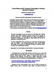
Fig. 1. Virtual reality facilities at Aalborg University VR Media Lab, Aalborg, Denmark, and medialogy Copenhagen, Denmark. Top-row from left: 8 × 3 m 160◦ . Panorama, the structure, and a representative view of the 2.5 × 2.5 m per side six-sided CAVE. Bottom-row from left: 1.5 × 1.5 m polarized-wall with projectors and polarized goggles, the 2.5 × 2.5 m interactive-wall, 2 × 0.59 in. HMD, 15 in. 3-D laptop, and 21 in. 3-D desktop.
[13]–[15]). Systems with large visualization displays have been proposed for immersive presentations, e.g., powerwalls, panorama arenas, as well as systems for individual use but allowing for high interaction, e.g., the Cave automatic virtual environment (CAVE) system [16], or systems with a head-mounted display (HMD). Fig. 1 shows examples of such facilities. VR systems may provide different input signals to the human sensor modalities in order to enhance a sense of presence in the generated virtual world. Other than vision, audio and touch represent main stimulated human sensors. However, vision being the dominant human sensor modality, much attention has been paid to the visualization aspect. In particular, different technologies have been developed for generating 3-D stereovisualization systems, confirming the fundamental role of stereo vision for most VR systems. The basic idea supporting stereoscopic visualization is that this is closer to the way we naturally see the world, which tells us about its great potential in teleoperation. We classify main approaches to stereo visualization in the following points. 1) Passive stereo. This approach multiplexes images in space. It can be subdivided into anaglyph (separation based on color filters), polarized (separation based on polarized filters), and separated displays (separation based on different displays very close to the user’s eye, as in HMDs). 2) Active stereo. This approach multiplexes images in time. It is typically based on shutter glasses (liquid crystal display (LCD) shutter panels in synchronization with visualization display). 3) Autostereoscopic stereo. This approach separates images based on special reflecting layers lying on the visualization display. It is typically subdivided into parallax barrier
and lenticular sheet [17]. It does not require users to wear goggles. Different stereoscopic approaches coupled with different display systems can be used. The latter is responsible for the degree of immersion, interactivity, isolation from the surroundings, etc. We classify among main components in the following points. 1) display size, from tiny HMD monitors to large 360◦ panoramic screens; 2) display structure, e.g., flat, curved, table-like, cubic shaped, head mounted; 3) projection modality, e.g., LCD/CRT monitors, DLP projectors, front/back projected screens; 4) image quality, e.g., resolution, brightness, contrast, color range, refresh rate; 5) observation condition, e.g., observer field of view, isolation from surrounding, stereo technology. B. Stereoscopy Benefits and Sacrifices Several works can be found in the paper addressing user performance in virtual environments in relation to display size [1], [11], [18]–[20], auditory cues, [21], haptic interfaces [14], [22], and how those aspects may affect user’s sense of presence, interaction ability, navigation skills, etc. Some works focus on stereoscopic visualization. Among these papers, works can be classified as either application specific, i.e., application-oriented user studies, or abstract test, i.e., abstract tasks and content with general performance criteria [1]. In the literature, test trials often deal with assessing the role of most dominant depth cues, e.g., interposition, binocular disparity, movement parallax [7], and their consequence to user adaptation to new contexts (e.g., user learning capabilities). The
Authorized licensed use limited to: UNIVERSITY OF HERTFORDSHIRE. Downloaded on December 21, 2009 at 06:00 from IEEE Xplore. Restrictions apply.
LIVATINO et al.: STEREO VIEWING AND VIRTUAL REALITY TECHNOLOGIES IN MOBILE ROBOT TELEGUIDE
TABLE I SUMMARY OF THE VR FACILITIES CHARACTERISTICS
parameters through which to assess stereoscopy benefits typically are item difficulty and user experience and accuracy and performance speed [3], [7]. Test variables altered during experiments include changes in monocular cues, texture type, relative distance, etc., other than stereoscopic versus monoscopic visualization. Everybody seems to agree that stereoscopic visualization presents the necessary information in a more natural way, which facilitates all human–machine interaction [3], and in particular, stereoscopy improves: comprehension and appreciation of presented visual input, perception of structure in visually complex scenes, spatial localization, motion judgment, concentration on different depth planes, and perception of surface materials. The main drawback, which have yet to prevent large application, is that users are called to make some sacrifices [8]. A stereo view may be hard to “get right” on the first attempt, or hardware may cause crosstalk, misalignment, image distortion (due to lens, displays, projectors), and all this may cause eye strain, double images perception, depth distortion, or look around distortion (typical for head-tracked displays). Most of the benefits of stereoscopy may affect robot teleguide. Among the conclusions gathered from the literature, we have the following: “Most tele-manipulation tasks require operators to have a good sense of the relative locations of objects in remote world” [3]; “stereopsis gives better impression of tele-presence and of 3-D layout” [23]; “binocular disparity and movement parallax are important contributors to depth perception” [7]; and “a robot in a dangerous environment can be controlled more carefully and quickly when the controller has a stereoscopic view” [4]. III. ROBOT TELEGUIDE AND 3-D TECHNOLOGIES A large variety of well-known state-of-the-art VR facilities are proposed. They represent a very suitable testing ground for the proposed investigation. (Fig. 1 shows some of the VR facilities, and Table I summarizes the main systems characteristics.)
1345
In particular, we have chosen VR systems adopting different stereo approaches and display systems. These are given in the following points. 1) 3-D laptop. 15 in. LCD thin-film transistor (TFT) display, image resolution 1280×800, truecolor (224 colors). Passive anaglyph stereo (red-cyan). Update rate 60 Hz (mono and stereo). High portability. 2) 3-D desktop. 21 in. CRT monitor, image resolution 1600×1200, truecolor. Passive anaglyph stereo and active shutters stereo. Update rates: 85 Hz (mono and anglyph stereo), 42.5 Hz (shutters stereo). Medium portability. 3) Interactive-wall. Rear-projected 2.5 × 2.5 m screen, one DLP projector, image resolution 800×600, truecolor [24]. Passive anaglyph stereo and active shutters stereo. Update rates: 120 Hz (mono and anaglyph stereo), 60 Hz (shutters stereo). 4) HMD. 2×0.59 in. OLED displays, image resolution 800×600, truecolor. Separated displays stereo. Update rate 60 Hz (mono and stereo). High portability. 5) Polarized-wall. Front projected 1.5 × 1.5 m silver screen, two DLP projectors, image resolution 1024×768. Passive stereo with polarized filters (standard linear filters 45◦ ). Update rate 60 Hz (stereo). Low portability. 6) Panorama. Front-projected 160◦ 8 × 3 m curved screen, three CRT projectors (edge blended), image resolution 1280 × 1024. Active shutters stereo. Update rates: 120 Hz (mono), 60 Hz (stereo). Fixed installation. 7) Six-sided CAVE. Complete CAVE 2.5 × 2.5 m per side, six rear-projected screens, six CRT projectors, image resolution 1280×1024. Active shutters stereo. Update rate 60 Hz (stereo). Fixed installation. In order to address support of different VR technologies in robot teleoperation, it is proposed to investigate the benefits of stereoscopic viewing in robot teleguide based on the analysis of a few factors typically described as predominant (e.g., in [10] and [25]), i.e., depth relationships and motion perception. Both the use of synthetic and real images is proposed in our experimentation. Several applications in telerobotics consider the use of synthetic images [1], [5], [7], because computergenerated scenarios can be easily controlled, and they have been demonstrated to be suitable for testing specific cues. Furthermore, real applications may use synthetic images in the case of environment reconstructed from laser data or when those images are used to complement real image sequences (e.g., incoming from onboard cameras), including the possibility of a calibrated mixed-reality visualization (e.g., in case of incomplete visual input). We have nevertheless also considered real images in our experiments in an attempt to identify the added value of those types of images in terms of some factors (e.g., presence and realism). Please also note that the use of synthetic or mixed scenarios is very often proposed in the paper as an actual working condition for many applications to supplement or substitute real (delayed) images coming in from remote sites. The proposed user study includes three tests. 1) Aptitude test. This test assesses the user’s ability in estimating egocentric distance and self-motion when using stereoscopic visualization under passive situations where
Authorized licensed use limited to: UNIVERSITY OF HERTFORDSHIRE. Downloaded on December 21, 2009 at 06:00 from IEEE Xplore. Restrictions apply.
1346
Fig. 2. Images from the egocentric distance trials (top-row and bottom-right) and self-motion trials (bottom-left). The far-end wall is not visible in the selfmotion experiment.
IEEE TRANSACTIONS ON ROBOTICS, VOL. 25, NO. 6, DECEMBER 2009
Fig. 4. trials.
Images from (bottom) the synthetic view trials and (top) real view
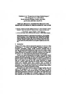
Fig. 5.
3MORDUC robot and its virtual replica.
Fig. 3. Images from (left) the collision-avoidance trials and (right) access width trials.
the operator only monitors the robot’s progression. The test is divided into two experiments: a) “egocentric distance,” where the user stands in front of a corridor while he/she is asked to estimate his/her distance to the far-end wall-plane; and b) “Self-motion,” where the user is driven along a corridor while he or she is asked to estimate the speed of the robot. Fig. 2 shows images from the experimental trials. 2) Interactive test. This test assesses the user’s ability to estimate relative and egocentric distance when using stereoscopic visualization under active situations when the operator has some control over the robot motion. The test is divided into two experiments: a) “collision avoidance,” where the user drives along a narrow corridor avoiding collisions against the walls; and b) “access width,” where the user is asked to the estimate access width of visible doorways while having the capability to pan the onboard camera. Fig. 3 shows images from the experiments trials. 3) Comparative test. This test assesses the capabilities of systems with different display technologies. In particular, the quality of a VR technology is judged through the analysis of five subjective parameters. The test is divided into two experiments: a) “synthetic views,” where the user observes images generated by a graphical simulator; and b) “real views,” where the user observes real stereoscopic images, recorded by a stereocamera setup for mobile robots. Fig. 4 shows images from the experiments trials.
IV. EXPERIMENTATION SETUP AND APPARATUS A. Software and Hardware Tests were, for the most part, based on a graphical simulator built in C++ language using the OpenGL graphic libraries. The OpenSG libraries were instead used on multidisplay facilities (panorama and CAVE). Tests ran on different computer platforms and VR hardware (introduced in previous sections). The graphical simulator included a virtual replica of a real robotic system. The robot is the 3MORDUC robot operating in the Robotics Laboratory at DIEES, University of Catania, Catania, Italy. Fig. 5 shows the 3MORDUC robot and its virtual replica. The mobile platform has a cylindrical shape that is 75 cm in diameter and 85 cm high. The platform is equipped with several sensors whose behavior was simulated in the case of the laser and the odometric system. When the virtual robot was telecontrolled, it moved accordingly to the same kinematics of the real mobile platform. Our software simulated the acquisition of a 2-D map from the onboard laser system. A 3-D map was then extrapolated from the 2-D map by elevating the map walls. Fig. 6 illustrates the process. The possibility for a user to interact with the robot and the environment depended on the chosen test. The user’s behavior was passive during the aptitude test and active during the interactive
Authorized licensed use limited to: UNIVERSITY OF HERTFORDSHIRE. Downloaded on December 21, 2009 at 06:00 from IEEE Xplore. Restrictions apply.
LIVATINO et al.: STEREO VIEWING AND VIRTUAL REALITY TECHNOLOGIES IN MOBILE ROBOT TELEGUIDE
1347
4) Robot Speed. Ten options. They ranged between 0.75 and 7.5 m/s. The speed had ten values starting from 0.75 and increasing in steps of 0.75 up to a maximum of 7.5. 5) Access width. Seven options. They ranged between 1 and 7 m. The width had seven values starting from 1 and increasing in steps of 1 up to a maximum of 7. The values were randomly chosen and were associated with the width of doorways. Fig. 3 (right-hand side) shows examples of observed doorways. Fig. 6. Process of generating a 3-D graphical environment from laser range information. The top-left image shows a 2-D map generated by the laser sensor. The bottom-left image shows a 3-D extrapolation of a portion of it. The rightimage shows a portion of the workspace visible to a user while navigating (on our interactive-wall).
Fig. 7. Examples of the robot workspace visualized to a user with different illumination and texture conditions.
test. Both the behaviors were proposed during the comparative test. In all tests, the users drove the robot using the mouse and keyboard arrow keys. This solution was considered suitable for our robot and its kinematics. A better command interface could nevertheless be devised for mobile robot teleguide. This was, however, out of the focus of the proposed study. Important for our experimentation was to have users telecontrolling the robot in the same way via different facilities. The environment chosen for the experiments was a typical indoor man-made environment where a robot may be actually operating, e.g., a factory after an accident has occurred. The graphical simulator was designed to estimate and record current robot position and orientation, distance to environment features, user’s number of collisions, and the completion time of the trials. B. Test Variables The simulator provided us with a controlled environment. We exploited this possibility by proposing different working conditions and scenarios. In particular, we randomly altered values of the five test variables that are described below. 1) Illumination. Three options: ambient light, on-board point light, environment point plus directional light. Fig. 7 shows examples of different illumination conditions. 2) Texture. Two options: uniform and brick-like. Fig. 7 shows examples with different textures. 3) Depth planes. Ten options. They ranged between 1 and 10 m from the position of the robot. The depth had ten values starting from 1 and increasing in steps of 1 up to a maximum of 10. Fig. 2 shows examples.
C. Stereo and Real Images The simulator was capable of generating different types of stereoscopic images. These were passive anaglyph, separate displays (dual images), and active shutters (alternate sequences). The software output was, therefore, adapted to the possibilities provided by the different VR hardware in controlling mono and stereo visualization. In addition to simulated images, we also used real images obtained by photographing or filming portions of an environment resembling the simulated one. Fig. 4 shows examples of both synthetic and real images of the environments used in our tests. Synthetic stereoscopic images were generated by our computer graphics software, while the real stereoscopic images were captured by a stereocamera setup for mobile robots with 7 cm of baseline. The cameras provided color images with a resolution of 640×480 pixels, which was suitable for low-bandwidth data transmission. V. USABILITY EVALUATION AND TEST TRIALS The user study aims to analyze the usability of the proposed 3-D technologies in a robot teleguide context. The proposed three tests are within-subject evaluations, and they are designed according to the recommendations gathered from [26] and [27] and the authors’ experience and previous study on the evaluation of VR applications [28], [29]. To guarantee a great internal variance for unbiased and reliable results, the target population was composed of participants with varying background and age. Participants had either no or moderate experience with VR devices and computer games. The test trials were conducted over several days. This is due to the overall execution time per participant to run all the required trials, the need for in-between breaks, and the time due to technical issues such as systems initialization and setup before a run can take place. The participants executed the same number of tasks under the same conditions and were assisted by a test monitor during each session. The task and facility assigned to each participant were ordered according to a pre-determined schedule. This was to counterbalance the sequence of tasks and to avoid fatigue and learning effects. The study included quantitative and qualitative evaluations. We are aware of the inaccurate use of terminologies related to quantitative and qualitative evaluations that occurred often [30]. We refer to definition provided in [31]. The data related to quantitative evaluations were gathered by our software during test trials, which represented the output of
Authorized licensed use limited to: UNIVERSITY OF HERTFORDSHIRE. Downloaded on December 21, 2009 at 06:00 from IEEE Xplore. Restrictions apply.
1348
the aptitude and interactive tests. These data consisted of sensor measurements, user inputs, and specific process simulations. They represented both user’s estimations and ground truth data, which were compared to estimate the accuracy of the users’ performance. The data related to qualitative evaluations were gathered through questionnaires, which represented the output of the comparative test. We conformed to the traditional approaches in terms of forms and questionnaires [27] with few additions [29]. Since experience in playing computer games was also taken into account, as was experience in teleoperation, the questionnaire also included questions about the gaming abilities, e.g., hours per week. Initially, we provided participants with an information sheet, consent form, and pretest screening. A practice session was then administrated before each experiment to make users acquainted with both the test and system. A thank you form was eventually provided. A pilot user study was performed before executing the formal study in order to debug and refine the design of the experiment.
A. Aptitude Tests 1) Usability Evaluation: Fourteen participants took part in the aptitude test. For practical reasons, the two experiments ran on two representative VR facilities: 3-D desktop and interactivewall. They are among most popular and economic 3-D visualization systems. Tests on each facility were both in mono and stereo viewing conditions (active shutters). Therefore, we had the following four configurations: 3-D desktop mono, 3-D desktop shutters, interactive-wall mono, interactive-wall shutters. Thirty trials were executed on each viewing condition for each facility and for each experiment. Therefore, we had a total of 240 trials per test-user. In this test, we controlled the environment illumination, texture, depth planes, and robot speed. During the egocentric distance experiment, a form containing users’ distance estimates was collected. The same procedure was followed in the case of the self-motion experiment (in this case, the form contained users’ self-motion estimates). The independent variable (factor) investigated in both experiments was the monoscopic versus stereoscopic visualization. The dependent variable was represented by distance estimate accuracy in the egocentric distance experiment and by the motion estimate accuracy in the self-motion experiment. 2) Test Trials: In egocentric distance trials, the users were asked to estimate the distance between their position and the far-end wall-plane. The wall-plane position was based on the depth planes variable (distances ranged 1–10 m). Fig. 2 shows images from trials. Transition of images and timing between subsequent trials were properly managed to assure that participants’ response would not be influenced by visually comparing current and previous trials, e.g., based on the perspective cue. In self-motion trials, the users were asked to estimate robot speed while they were driven along a corridor. The corridor was represented as in the egocentric distance trials; however, the farend wall-plane was not visible. The robot motion was based on
IEEE TRANSACTIONS ON ROBOTICS, VOL. 25, NO. 6, DECEMBER 2009
Fig. 8. Top-view of the 2-D map used for the interactive trials together with the locations “A,” “B,” “C,” and the enclosed paths. “R” represents the robot. The numbers indicate sizes in meters.
the robot speed variable (velocity ranged 0.75–7.5 m/s). Fig. 2 (bottom-left) shows an example. The trials output was represented by the users’ estimated distances to far-end wall-plane and self-motion. When processing users’ estimations of distances and self-motion, an error-rate index was calculated as the percent error in an estimate relative to the true difference [32] (the real value is subtracted by the estimated one, and the result is divided by the estimated value). B. Interactive Tests 1) Usability Evaluation: Ten participants took part in the aptitude test. For practical reasons, the two experiments ran on two representative VR facilities: the 3-D desktop and interactivewall. They are among the most popular and economic 3-D visualization systems. Tests on each facility were both in mono and stereo viewing conditions (active shutters). Therefore, we had the following four configurations: 3-D desktop mono, 3-D desktop shutters, interactive-wall mono, interactive-wall shutters. Twenty-five trials were executed on each viewing for each facility and for each experiment. Therefore, we had a total of 200 trials per test-user. In this test, we controlled the environment illumination, texture, and access width. During the collision-avoidance experiment, a log-file was generated that contained the collision-rate data. This resulted from the number of performed collisions divided by the completion time. During the access-width experiment, a form containing users’ distance estimates was collected. The independent variable (factor) investigated in both experiments is the monoscopic versus stereoscopic visualization. The dependent variable is represented by the collision rate in the collision-avoidance experiment and by the distance estimate accuracy in the access-width experiment. 2) Test Trials: In the interactive test, each trial combined the collision-avoidance and access-width experiments. Fig. 8 shows the 2-D map used for the interactive trials. The user started from either position “A” or “B” (randomly selected) and was asked to reach position “C” while avoiding collisions with walls. This phase represented the CollisionAvoidance experiment. Once in position “C,” the access-width experiment started. A large hall was presented in front of the user, and four separate doorways with different access widths became visible. Fig. 3
Authorized licensed use limited to: UNIVERSITY OF HERTFORDSHIRE. Downloaded on December 21, 2009 at 06:00 from IEEE Xplore. Restrictions apply.
LIVATINO et al.: STEREO VIEWING AND VIRTUAL REALITY TECHNOLOGIES IN MOBILE ROBOT TELEGUIDE
showed views from positions “B” and “C.” The doorway widths were chosen as a random subset of four elements from the seven possible values of the test variable access width. The user was asked to observe the four doorways from position “C” and estimate their widths. The user view could only rotate around the vertical axis in the “C” location. Please note that once the robot reached the position “C,” it could no longer move from its position. This condition was set to have all users and all trials observing the doorways from the same position. In position “C,” the camera was nevertheless given the possibility to pan within a limited range. This possibility is suggested in [7] to enhance depth awareness. Panning the camera was expected not to bias the result because users were given sufficient time during an observation to explore the different panning positions (1 min was given to observe the four doorways and estimate their width). The trials output was represented by the number of collisions against walls, trial completion time, and users’ estimated width of presented doorways (relative distances). The error rate for estimating distance accuracy was calculated as in the egocentric distance experiment. C. Comparative Tests 1) Usability Evaluation: Twenty-four participants took part in the comparative test. Tests on each facility were only in stereo viewing, as described in the following points. 1) The synthetic views experiment ran on all seven VR facilities. On some facilities, more than one configuration was used, giving a total of nine different configurations. They are 3-D laptop anaglyph (LA), 3-D desktop anaglyph (DA), 3-D desktop shutters (DS), interactivewall anaglyph (IA), interactive-wall shutters (IS), head mounted display (HM), polarized-wall (PW), panorama (PA), and six-sided CAVE (CA). 2) The real views experiment ran on four VR facilities. On some facilities, more than one configuration was used, giving a total of six different configurations. They are LA, DA, DS, IA, IS, and HMD. Each user executed one trial for each facility and for each experiment. Therefore, we had a total of 15 trials per test-user. The quality of a VR technology was judged through the analysis of five subjective parameters. They were 1) adequacy to application, (suitability to the specific task); 2) realism (realistic visual appearance); 3) presence (sense of presence); 4) 3-D impression (depth impression); 5) viewing comfort (eye strain and general body reaction). The chosen categorization followed a methodology proposed in other studies [7], which we had extended and adapted to our specific project objectives. At the end of each trial an evaluation questionnaire was provided. Questionnaires were designed after the five proposed subjective parameters. For example, the questionnaire for the Realism parameter included the following questions: “How realistic is the environment layout?”, “How realistic are the visualized objects size and shape?”, “How natural was the driving?”, and “What mark would you give as general level of realism?” The
1349
Fig. 9. Top-view description of the (right) negative and (left) positive parallax. “L” stands for left and “R” for right.
questionnaire also included user’s suggestion for improvement and general remarks. A conclusive comparative questionnaire was provided at the end of each experiment. The 3-D Impression parameter was further divided into “in front of” and “behind” screen, according to the different parallax situation which may arise (positive parallax is behind the screen, and negative parallax is in front of the screen). Fig. 9 graphically represents both the parallax situations. The data collected were analyzed through the use of descriptive statistics. 2) Test Trials: The synthetic views trials were interactive. In each facility, the user was left for 3 min of free driving and exploring the simulated environment as well as changing the test variables illumination and texture (the other variables were set to constant value). During the real views trials, the user was instead observing prerecorded images and videos captured by the stereocamera setup. The real images and videos showed a real environment similar to the computer generated one. The output of the trials was represented by the answers given to questionnaires. Fig. 10 shows test-users during some comparative test trials. VI. APTITUDE TEST OUTCOMES A. Results The aptitude test focuses on the potential advantage of using stereoscopic visualization under passive situations. We measure statistical significance of results by estimating the analysis of variance (ANOVA). In particular, a one-way ANOVA is applied. The result of the ANOVA when considering different sets provides a p-value.1 We set p = 0.05 as the threshold. Under stereoscopic visualization, users performed significantly better in the egocentric distance experiment. The variance analysis with repeated measures (ANOVA) showed a main effect of stereo viewing on percentage of correct answers. We obtained a p-value of p = 0.0257, F(2, 26) = 5.38. The improvement when comparing mean values was 27%. Fig. 11 (left-hand side) shows accuracy of a typical run in terms of percentage of error, with one subject running 30 trials. The figure (right-hand side) shows percentage of correct answers for all 14 users. The self-motion experiment did not lead to significant results. B. Analysis The result obtained for the egocentric distance experiment demonstrated the advantage of using stereo viewing under static observation. The improvement is demonstrated despite strong 1 The p-value represents the probability for the null hypothesis that all samples are drawn from the same population (or from different populations with the same mean). The choice of a critical p-value to determine whether the result is judged “statistically significant” is typically left to the researcher, but it is common to declare a result significant if the p-value is less than 0.05 or 0.01 [33].
Authorized licensed use limited to: UNIVERSITY OF HERTFORDSHIRE. Downloaded on December 21, 2009 at 06:00 from IEEE Xplore. Restrictions apply.
1350
IEEE TRANSACTIONS ON ROBOTICS, VOL. 25, NO. 6, DECEMBER 2009
Fig. 10. Test-users during the comparative test. The left-column images show testing in the 160◦ panorama. The central-column images and the top-right one show testing in the six-sided CAVE. The bottom-right image shows a concurrent comparison of panorama and 3-D desktop.
Fig. 11. Egocentric Distance experiment. The left-hand side shows accuracy of a typical run in terms of percentage of error, with one subject running 30 trials. The performance in mono viewing is represented by a continuous line and the one in stereo viewing by a dashed line. The right-hand side shows percentage of correct answers for all 14 users.
monocular depth cues are shown in the visualized scene. In particular, the view perspective was expected to improve users’ guess accuracy. In the case of self-motion experiment, the lack of performance improvement under stereo viewing seemed to agree with the theory of Hubona et al. [5], with motion saturating the visual system so that stereopsis would not play a relevant role. In addition, this is a situation where “stereo from motion” may arise [34] so that binocular stereo does not represent an added value [2].
VII. INTERACTIVE TEST OUTCOMES A. Results The interactive test focuses on the potential advantage of using stereoscopic visualization under active situations. We measure statistical significance of results by estimating the one-way ANOVA. Under stereoscopic visualization users performed significantly better in the access width experiment. The result of the ANOVA showed a p-value of p = 0.0145, F(2, 18) = 7.32. The
Authorized licensed use limited to: UNIVERSITY OF HERTFORDSHIRE. Downloaded on December 21, 2009 at 06:00 from IEEE Xplore. Restrictions apply.
LIVATINO et al.: STEREO VIEWING AND VIRTUAL REALITY TECHNOLOGIES IN MOBILE ROBOT TELEGUIDE
1351
Fig. 12. Access width experiment. The left-hand side shows accuracy of a typical run in terms of percentage of error, with one subject running 25 trials. The performance in mono viewing is represented by a continuous line and the one in stereo viewing by a dashed line. The right-hand side shows percentage of correct answers for all 10 users.
improvement when comparing mean values was 35%. Fig. 12 (left-hand side) shows accuracy of a typical run in terms of percentage of error, with one subject running 25 trials. The figure (right-hand side) shows the percentage of correct answers for all 10 users.
TABLE II RESULTS OF THE COMPARATIVE TEST FOR SYNTHETIC AND REAL IMAGES
B. Analysis The result obtained for the access width experiment demonstrated the advantage of stereoscopic viewing when estimating distances. Compared with the estimation of egocentric distance of our experiment, in the Access Width experiment, the user can take advantage of the presence of additional monocular depth-cues to estimate the relative distance, object occlusion and texture gradient (other than perspective cue) among them. This makes the obtained result very relevant. Furthermore, this relevance is underlined by the presence of test-users with a high level of visual attention who, according to [11] and [18], should gain less from using stereo viewing. The visual attention was estimated through a specific test. In the case of the collision-avoidance experiment, the lack of improvement under stereoscopic conditions may be due to different issues that call for further studies. One issue is the “workspace design.” This should have challenged human driving skills more. Another issue is (again) the less-relevant contribution of binocular stereo in a motion-based (stop-and-go) situation. Furthermore, the contribution to collision avoidance of environment texture and illumination (responsible for creating situations of visual contrast) would also need to be investigated because these are the factors affecting the detection of wall proximity. VIII. COMPARATIVE TEST OUTCOMES The results of the comparative test are based on data collected through the questionnaires. These are summarized in Table II and presented for each subjective parameter in the graph diagrams of Figs. 13–17. The diagrams illustrate the average level
of appreciation of our 24 test-users for the different subjective parameters. The results are commented and analyzed below for each subjective parameter. The analysis is based on facilities performance and comments provided by the test-users, which are often compared with authors’ expectations (based on literature results).
Authorized licensed use limited to: UNIVERSITY OF HERTFORDSHIRE. Downloaded on December 21, 2009 at 06:00 from IEEE Xplore. Restrictions apply.
1352
Fig. 13. Results for the “Adequacy-to-Application” parameter. The x-axis indicates VR facilities (see text). The y-axis indicates the average level of appreciation of test users (1–10 interval). The left-hand side represents results when using synthetic images. The right-hand side shows results with real images.
IEEE TRANSACTIONS ON ROBOTICS, VOL. 25, NO. 6, DECEMBER 2009
Fig. 16. Results for the “3-D Impression” parameter. The x-axis indicates VR facilities (see text). The y-axis indicates the average level of appreciation of test-users (1–10 interval). The left-hand diagram represents results when using synthetic images. The right-hand side shows results with real images. The two values reported for the 3-D impression subjective parameter are related to the negative and positive parallax. In particular, the positive parallax is represented by (red) lighter bars and negative parallax by (blue) darker bars.
Fig. 14. Results for the “Realism” parameter. The x-axis indicates VR facilities (see text). The y-axis indicates the average level of appreciation of test-users (1–10 interval). The left-hand side represents results when using synthetic images. The right-hand side shows results with real images.
Fig. 17. Results for the “Viewing Comfort” parameter. The x-axis indicates VR facilities (see text). The y-axis indicates the average level of appreciation of test-users (1–10 interval). The left-hand side represents results when using synthetic images. The right-hand side shows results with real images.
Fig. 15. Results for the “Presence” parameter. The x-axis indicates VR facilities (see text). The y-axis indicates the average level of appreciation of test-users (1–10 interval). The left-hand side represents results when using synthetic images. The right-hand side shows results with real images.
A. Adequacy to Application 1) Results: Fig. 13 shows results on the different facilities. Large visualization screens (CAVE, panorama, polarized, and interactive walls) were generally judged more suitable for mobile robot teleguide both for synthetic and real images. The HMD and desktop shutter followed. Small facilities with anaglyph stereo performed the worst, getting the lowest scores in the case of real images. 2) Analysis: The high scores given to large visualization facilities goes along with Demiralp et al. considerations [1], who assert that “looking-out” tasks (i.e., where the user views the world from inside-out as in our case) require users to use their peripheral vision more than in “looking-in” tasks, e.g., small
object manipulation. Larger screens also present environment characteristics closer to their real dimension, which enforces adequacy of these displays to the application. The CAVE seems very suitable for careful interactive teledrive. In fact, by already moving the head and body around, a user can observe the surrounding environment and get a clear perception of the proximity of the walls to the robot platform. The walls and panorama offered good visual feedback, but the interaction was more for trained users through a 3-D mouse. The 3-D desktop visual feedback is much reduced, which affects and limit interaction capability. This system was nevertheless believed to be very suitable as low-cost facility for remote driving and is still better than the 3-D laptop because of the possibility for active stereo visualization. The score obtained by the HMD system follows, which is lower than expected. The HMD was, in fact, considered invasive and tiring in the long run. The good level of isolation from the surroundings was appreciated on the HMD, but the larger screen facilities were claimed to provide comparable isolation with less fatigue for a user. When looking at the results obtained with the facilities adopting anaglyph stereo, we can see that this approach reduces the adequacy level. Experiments with real images yielded results
Authorized licensed use limited to: UNIVERSITY OF HERTFORDSHIRE. Downloaded on December 21, 2009 at 06:00 from IEEE Xplore. Restrictions apply.
LIVATINO et al.: STEREO VIEWING AND VIRTUAL REALITY TECHNOLOGIES IN MOBILE ROBOT TELEGUIDE
that were very similar to synthetic images, except for when anaglyph stereo was adopted. In this case, the performance was comparably worse and commented as unacceptable for long driving sessions. B. Realism 1) Results: Fig. 14 shows the results. Large visualization screens were considered to provide the higher level of realism both for synthetic and real images. The CAVE was the best for synthetic images. The polarized and shutter stereo got better scores than separate display and anaglyph stereo. The HMD followed after the large screens but preceded the small screens. Small facilities with anaglyph stereo got the lowest scores. 2) Analysis: Large screens are considered more realistic because the environment scenes and objects are shown in their natural size. Visual details may, however, appear difficult to appreciate in some facilities when the user is close to the screen. In the case of panorama, the above effect diminished because users sat at a predefined distance. The CAVE performed the best. This is due to its large screen and the head-coupled tracking. The wall facilities followed, and their performance was lower when anaglyph stereo was adopted. The HMD performed worse than large screens but better than small screens (3-D desktop and laptop). Small screens were judged as the less realistic VR facilities. Image compression and resize was claimed to affect realism. Anaglyph stereo scored always low when adopted (as expected), but the results were better than for the case of the adequacy parameter. The performance was generally higher on real images because the visualized textures were more photo-realistic than the synthetic ones. The performance with real images was, however, lower than the authors expected. The reason for this was the low image resolution and possibly the relative large camera baseline. The latter may have caused some visualized object to appear “cartoon-like” in some occasions, which is a phenomenon that is typical in hyperstereo. Please note that the baseline choice was a compromise among realism, technical constraints (our real stereo-camera did not allow us to go less than 7 cm), and a suitable level of 3-D Impression in relation to the expected average distance to observed objects. 3-D Impression and Realism appeared, therefore, clearly related. These are two parameters to trade off in applications involving stereo viewing and requiring accurate distance estimation. C. Presence 1) Results: Fig. 15 shows the results. Large visualization screens are considered to be the best except when anaglyph is used (interactive-wall). In particular, the anaglyph shows a substantial loss in the perceived sense of presence on the interactive-wall for both for synthetic and real images. The CAVE is again the best for synthetic images, but the interactive wall with shutters performs better than the panorama and the polarized-wall. The HMD scores are generally in between large and small screens. The laptop with anaglyph stereo gets lowest score on both types of image.
1353
2) Analysis: A main role was played by the screen size (as expected). Large screens largely involve human peripheral vision, and this affects the sense of presence. An important role was also played by the use of head-coupled tracking. As a consequence, the CAVE was judged as the best VR facility, and the interactive wall followed. The panorama was next in the table. In fact, this system was not head-tracked, but it had a very large screen and field-of-view. The polarized wall was placed after the panorama. The result obtained with HMD may be considered disappointing. This facility was penalized by the so-called tunnel-vision effect, which was claimed to reduce the sense of “being there.” We expect that latest HMDs with wide fieldof-view will perform much better. The major role played by screen size was also seen by the better performance of our 21 in. desktop when compared with the 15 in. laptop. The user involvement decreased with anaglyph stereo (except in case of the desktop with real images). This result was clearly shown when testing on the interactive wall. In this case, the loss of performance was due to eye strain arising from rearprojection (screen-altered colors causing high crosstalk). The anaglyph stereo performed slightly better on real images because these images provided higher realism. Similar results were obtained for synthetic and real images in the HMD, laptop, and interactive-wall with active shutters. We did not find an explanation for the result obtained with real images on the desktop. In this facility, anaglyph stereo and active shutters perform equally. D. 3-D Impression 1) Results: Fig. 16 shows the results. The results are divided into “behind” display (positive parallax) and “in front of” display (negative parallax). The best performing facilities are the CAVE and panorama. The polarized-wall and the desktop with shutters follow. The good desktop performance (in case of shutters) is noted both for synthetic and real images. Desktop with anaglyph performs poorly in the case of real images. 2) Analysis: The best results were obtained in the CAVE, where the 3-D impression in front of the screen was particularly appreciated, and in the panorama, where the sharp and bright images due to front-projection technology were much appreciated. Surprisingly, in the case of desktop with active shutters, we obtained results comparable in average with those obtained in the wall facilities and CAVE. Even more surprising were the results on the desktop facility when we looked at the 3-D impression behind the display. Confirmation that 3-D desktop-perceived depth impression can be high is found in the study of Jones et al. [6], which shows how the range of depth tolerated before loss of stereo fusion can be quite large on a desktop. We have also noted that in our case, the range of perceived depth in the 3-D desktop typically corresponds to a larger workspace portion than in largescreen systems. In other words, the same workspace portion corresponds to a wider range of perceived depth on a large screen, but we typically “lose stereo” after 5–7 m. The performance on the HMD was high. The bright OLED screens provided sharp images, which helped human stereo
Authorized licensed use limited to: UNIVERSITY OF HERTFORDSHIRE. Downloaded on December 21, 2009 at 06:00 from IEEE Xplore. Restrictions apply.
1354
IEEE TRANSACTIONS ON ROBOTICS, VOL. 25, NO. 6, DECEMBER 2009
fusion, while the Separate Displays approach guaranteed no crosstalk. The 3-D Impression with real images provided results for the most comparable with those obtained with synthetic images (on the considered facilities). We observed that the experiments with real images seemed to particularly penalize the desktop with anaglyph stereo. We believe that this result is due to an unfortunate matching among low-resolution images, desktop resolution, and screen size. Therefore, we do not consider this result as a regular trend, and we look forward to further experiments to confirm this supposition. E. Viewing Comfort 1) Results: Fig. 17 shows the results. The panorama and polarized-wall got the best score for synthetic images, followed by the interactive-wall with shutters. The latter, together with the HMD, performs best for real images. For synthetic images, the CAVE result follows the HMD, and it is the same for the desktop with shutters. The facilities equipped with anaglyph stereo occupy the lower positions on the diagrams, and in particular, the worst performance is assigned to the interactive-wall with anaglyph stereo. 2) Analysis: Large displays facilities were, in general, claimed more suitable to robot teleguide applications. However, they had limitations in comfort, depending on head-tracking and type of robot movements. The anaglyph stereo technology strongly affected viewing comfort. In particular, the level of comfort was acceptable in the case of the desktop and laptop (but it called for high image brightness), and it was unacceptable in the interactive-wall because of the high crosstalk arising from rear projection. The head-tracker could produce some disturbing effects (nausea), and it was responsible for lowering the scores obtained by the CAVE and HMD. In particular, the limitation in comfort arose when robot speed was high. This is because motion sickness may most likely take place in facilities with a large field-of-view. The best performance assigned to the panorama and polarized-wall confirmed benefits of front-projection and polarized filters. They provide limited eye strain, crosstalk, and a greater color reproduction. The lower performance of CAVE compared with interactive-wall was due to head-coupled tracking, while the better performance of HMD compared with CAVE seemed to be due to the lower field-of-view that improved comfort. The desktop was more comfortable than laptop, mainly because of the active shutters. Results with real images were somehow comparable with those obtained with synthetic images. IX. CONCLUSION The proposed study investigated the role of 3-D stereoscopic visualization in applications related to mobile robot teleguide. This paper also assessed the use of seven different VR systems in the proposed application area. The proposed study aimed at representing a useful input for system designers and researchers wishing to use the same or similar facilities in telerobotics or other application areas.
A usability study was proposed that involved several participants and a man-made indoor workspace as the testing environment. The study comprised two quantitative evaluations (the aptitude and interactive tests) subdivided into four experiments (egocentric distance, self-motion, collision avoidance, and access width) and one qualitative evaluation (the comparative test) subdivided in two experiments (synthetic and real views). The comparative test was designed according to five different subjective parameters: adequacy to application, realism, presence, 3-D impression, and viewing comfort. During the experimentation trials, participants were asked to teleguide a mobile robot under different environment conditions, image types (real and synthetic), and viewing modalities (stereo and mono). The results of the aptitude and interactive tests showed a statistically significant performance improvement in estimating egocentric and relative distances when stereoscopic viewing was adopted. The results did not show significant improvement when estimating self-motion and collision avoidance, which we will address in further study. From the results of the comparative test, we have learned that there is no VR facility that performs best on all proposed parameters. The large displays facilities are more suitable for mobile robot teleguide, but some have limitations in comfort. We acknowledge that physical dimensions and portability play a big role in the choice of a VR system; therefore, costeffective solutions were included in our study. In this regard, the results with anaglyph stereo were beyond expectation, leading to a significant improvement over mono viewing. Its use can nevertheless be recommended on laptops and desktops with characteristics similar to ours (the viewing comfort was unacceptable on our interactive-wall). We leave any further conclusions to system designers who can look at the result of the presented study and make adequate decisions based on their application context and budget. We are now developing experiments on an online interaction with a remote mobile robot based on the experience gained with this paper. We believe that 3-D stereoscopic visualization will be adopted in many application fields, e.g., computer games and multimedia, and its use in telerobotics will certainly become popular. ACKNOWLEDGMENT The authors would like to thank T. Gambin and L. Mosiej, from the Technical University of Warsaw, Warsaw, Poland, for their valuable contribution during their studies at Aalborg University, Aalborg, Denmark, in relation to testing the robot teleguide application with real images. The authors would also like to thank C. Koeffel from Upper Austria University, Hagenberg, Austria, and Aalborg University, Copenhagen, Denmark for her contribution to the usability study design. REFERENCES [1] C. Demiralp, C. Jackson, D. Karelitz, S. Zhang, and D. Laidlaw, “Cave and fishtank virtual-reality displays: A qualitative and quantitative comparison,” IEEE Trans. Vis. Comput. Graph., vol. 12, no. 3, pp. 323–330, May–Jun. 2006.
Authorized licensed use limited to: UNIVERSITY OF HERTFORDSHIRE. Downloaded on December 21, 2009 at 06:00 from IEEE Xplore. Restrictions apply.
LIVATINO et al.: STEREO VIEWING AND VIRTUAL REALITY TECHNOLOGIES IN MOBILE ROBOT TELEGUIDE
[2] C. Ware and G. Franck, “Evaluating stereo and motion cues for visualizing information nets in 3 dimensions,” ACM Trans. Comput. Graph., vol. 15, no. 2, pp. 131–140, 1996. [3] D. Drascic, “Skill acquisition and task performance in teleoperation using monoscopic and stereoscopic video remote viewing,” in Proc. 35th Human Factors Soc., 1991, pp. 1367–1371. [4] O. Bimber, N. Dogson, G. Favalora, D. Luebke, R. Raskar, and C. Slinger, “The ultimate display: What will it be?” in Proc. Comput. Graph. ACM SIGGRAPH Panels, 2005, pp. 2–4. [5] G. Hubona, G. Shirah, and D. Fout, “The effects of motion and stereopsis on three-dimensional visualization,” Int. J. Human-Comput. Stud., vol. 46, pp. 609–627, 1997. [6] G. Jones, D. Lee, N. Holliman, and D. Ezra, “Controlling perceived depth in stereoscopic images,” in Proc. SPIE, Stereoscopic Displays VR Syst. VIII, 2001, vol. 4297, pp. 42–54. [7] U. Naepflin and M. Menozzi, “Can movement parallax compensate lacking stereopsis in spatial explorative tasks?” Elsevier Displays, vol. 22, no. 5, pp. 157–164, 2001. [8] I. Sexton and P. Surman, “Stereoscopic and autostereoscopic display systems,” IEEE Signal Process. Mag., vol. 16, no. 3, pp. 85–99, May 1999. [9] S. L. Hill, “Scalable multi-view stereo camera array for real world realtime image capture and three-dimensional displays,” Master’s thesis, Mass. Inst. Technol., Cambridge, MA, 2004. [10] D. Kasik, J. Troy, S. Amorosi, M. Murray, and S. Swamy, “Evaluating graphics displays for complex 3D models,” IEEE Comput. Graph. Appl., vol. 22, no. 3, pp. 56–64, May–Jun. 2002. [11] E. Patrick, D. Cosgrove, A. Slavkovic, J. Rode, T. Verratti, and G. Chiselko, “Using a large projection screen as an alternative to head-mounted displays for virtual environments,” in Proc. Conf. Human Factors Comput. Syst., 2000, vol. 2, pp. 478–485. [12] C. Swindells, A. Barry, and I. Hajshirmohammadi, “Comparing cave, wall, and desktop displays for navigation and wayfinding in complex 3D models,” in Proc. Comput. Graph. Int., 2004, pp. 420–427. [13] T. Boult, “DOVE: Dolphin Omni-directional video equipment,” in Proc. Int. Conf. Robot. Autom., 2000, pp. 214–220. [14] R. Ott, M. Gutierrez, D. Thalmann, and F. Vexo, “Advanced VR technologies for surveillance and security,” in Proc. Int. Conf. VR Continuum Its Appl., 2006, pp. 163–170. [15] C. Kurashima, M. Cabral, and M. Zuffo, “A system for rendering panoramic tele-immersion images,” in Proc. IEEE VR: Workshop Emerging Display Technol., 2005, pp. 7–10. [16] C. Cruz-Neira, D. Sandin, and T. DeFanti, “Surround-screen projectionbased virtual reality: The design and implementation of the CAVE,” in Proc. Comput. Graph. SIGGRAPH, 1993, pp. 73–80. [17] G. J. Kim, Designing Virtual Reality Systems. The Structured Approach. New York: Springer-Verlag, 2005. [18] F. Tyndiuk, G. Thomas, V. Lespinet-Najib, and C. Schlick, “Cognitive comparison of 3D interaction in front of large vs. small displays,” in Proc. Int. Conf. Virtual Reality Softw. Technol., 2003, pp. 117– 123. [19] D. Tan, D. Gergle, P. Scupelli, and R. Pausch, “With similar visual angles, larger displays improve spatial performance,” in Proc. Int. Conf. Virtual Reality Softw. Technol., 2005, pp. 46–55. [20] T. Ni, G. Schmidt, O. Staadt, M. Livingston, R. Ball, and R. May, “A survey of high-resolution display technologies, techniques, and applications,” in Proc. IEEE VR, 2006, pp. 223–236. [21] B. Riecke, J. Schulte-Pelkum, F. Caniard, and H. B¨ulthoff, “Influence of auditory cues on the visually-induced self-motion illusion (circular vection) in virtual reality,” in Proc. Int. Workshop Presence, 2005, pp. 49– 57. [22] S. Lee, G. Sukhatme, G. J. Kim, and C. Park, “Haptic teleoperation of a mobile robot: A user study,” Presence: Teleoperators & Virtual Environ., vol. 14, no. 3, pp. 345–365, 2005. [23] M. Bocker, D. Runde, and L. Muhlback, “On the reproduction of motion parallax in videocommunications,” in Proc. 39th Human Factors Soc., 1995, pp. 198–202. [24] S. Livatino, V. Agerbech, A. Johansen, and B. Johansen, “Designing a virtual reality game for the CAVE,” in Proc. Eurographics IC Conf., 2006, pp. 111–115. [25] M. Matlin and H. Foley, Sensation and Perception. Boston, MA: Allyn & Bacon, 1983. [26] J. Rubin, Handbook of Usability Testing: How to Plan, Design and Conduct Effective Tests. New York: Wiley, 1993. [27] J. Nielson, Usability Engineering. San Mateo, CA: Morgan Kaufmann, 1993.
1355
[28] S. Livatino and C. Koeffel, “Handbook for Evaluation studies in virtual reality,” in Proc. IEEE Int. Conf. Virtual Environ., Human-Comput. Interface Meas. Syst., 2007, pp. 1–6. [29] S. Livatino and C. Koffel, Advances in Human Computer Interaction: Simple Guidelines for Testing Virtual Reality Applications. Vienna, Austria: I-Tech, Dec. 2008. [30] P. Hodgson. (2003). Blueprint Usability—Quantitative and Qualitative Data. [Online]. Available: http://www.blueprintusability.com/topics/ articlequantqual.html [31] R. S. Witte, Statistics, 3rd ed. New York: Holt, Rinehart, and Winston, 1989. [32] A. Gaggioli and R. Breining, “Perception and cognition in immersive virtual reality,” in Proc. Commun. Through Virtual Technol.: Identity Community Technol. Internet Age, 2001, pp. 71–86. [33] Mathworks Inc. The Matlab on-line HELP. [Online]. Available: http:www.matworks.com [34] J. Crowley and H. I. Christensen, Vision as Process, New York: SpringerVerlag, 1995. Salvatore Livatino received the M.Sc. degree in computer science from the University of Pisa, Pisa, Italy, in 1993, with a specialization undertaken at the Scuola Superiore S.Anna, Pisa, where he pursued his research activity with the laboratories Advanced Robotics Technology and Systems (ARTS) and Perceptual Robotics (PERCRO) during 1992–1995, and the Ph.D. degree from Aalborg University, Aalborg, Denmark. He was a Visiting Researcher with the University of Leeds, Leeds, U.K., in 1995, INRIA, Grenoble, France, in 1996, and University of Edinburgh, Edinburgh, U.K., in 2001. He was with the Department of Media Technology under the Medialogy Studies and in collaboration with the VR Media Lab, Aalborg University, for 11 years, first as a Research Fellow and then as an Assistant and Associate Professor. Since 2008, he has been with the School of Engineering and Technology, University of Hertfordshire, Hatfield, U.K. His current research interests include virtual reality, computer graphics, computer vision, and mobile robotics, with works combining those fields, e.g., photorealistic image synthesis and vision-based robot navigation. He is the author of several journal and conference papers. His most recent research works concern the use of 3-D visualization and virtual reality facilities in telerobotics, cultural heritage, and computer games. His teaching experience has mostly been within problem-based learning and multidisciplinary educations. Giovanni Muscato (M’91–SM’01) received the Electrical Engineering degree from the University of Catania, Catania, Italy, in 1988. After completing graduation, he was with the Centro di Studi sui Sistemi, Turin, Italy. In 1990, he joined the Dipartimento di Ingegneria Elettrica Elettronica e dei Sistemi, University of Catania, where he is Currently a Full-Time Professor of robotics and automatic control. His current research interest includes model reduction, service robotics, and the use of softcomputing techniques in the modeling and control of dynamical systems. He was the coordinator of the EC project Robovolc: A Robot for Volcano Explorations, and is the local coordinator of several national and European projects in robotics. He is the author of more than 200 papers in scientific journals and conference proceedings and three books in the fields of control and robotics. Prof. Muscato is the Co-chair of the Service Robotics Technical Committee. He is with the Board of Trustees of the Climbing and Walking Robots (CLAWAR) Association. Filippo Privitera received the M.Sc. equivalent degree from the Scuola Superiore di Catania, Catania, Italy, in 2006 and the Master of Electronic Engineering degree from the University of Catania in 2005. He is currently with the Scuola Superiore di Catania, where he has been engaged for Dada S.p.A. in the Simply.com division. His current research interests include telerobotics, 3-D systems, recommendation systems, and behavioral targeting.
Authorized licensed use limited to: UNIVERSITY OF HERTFORDSHIRE. Downloaded on December 21, 2009 at 06:00 from IEEE Xplore. Restrictions apply.