Olaf Faber3 and Hans-Jürgen Niemann3 ... large structure exposed to wind loading. ... measured at 18 points in a wind tunnel in recent experiments [1].
Stochastic Structural Optimization for Dynamic Load Processes Heinrich Weber1, Dietrich Hartmann1, Armin Lenzen2, Olaf Faber3 and Hans-Jürgen Niemann3 1
Institute of Computational Engineering, Ruhr-University Bochum, Germany Wölfel Beratende Ingenieure, Höchberg bei Würzburg, Germany 3 Building Aerodynamics Laboratory, Ruhr-University Bochum, Germany
2
Abstract. The optimization of structures with respect to reliability is a field of research of interest in civil engineering. Especially the problem of structures subjected to stochastic dynamic loads leads to an extensive task. As a consequence, the efficiency of an approach is very important. The method used here for the dynamical structural analysis, therefore, is the covariance analysis. By a combination of a shaping filter and a finite element method specified parameters describing the probability density function of stress amplitudes are received for multi-correlated loading. A steel structure serves as an example of use for this method. The advantages of the covariance method will be demonstrated for the case of a stochastic structural optimization. In this context, a multi-step solution is proposed which uses different methods with increasing accuracy both for the optimization and the computation of the reliability.
1
Introduction
With the increase of computational capabilities the concept of a stochastic dimensioning of structures is gaining more and more popularity. Such a concept has the advantage that it can represent the real world qualities of cross-sections or loads based on probabilities and deviations. The main disadvantage, i.e. the timeconsuming computation of the reliability, especially when using a precise simulation method, will not play an important role in the future [2]. Nevertheless, time remains a problem, even if the computer power increases, e.g. structural optimization problems with respect to the reliability, assuming dynamically loaded structures. A typical example for this problem domain is a large structure exposed to wind loading. In this case, stress processes are induced which can cause fatigue problems. Here, many time-consuming problems get together, e.g. a dynamical structural analysis, cycle counting for the stress amplitudes, damage accumulation for the fatigue analysis, reliability computation and optimization. These partial problems act on different time levels. The loading is modeled as a multi-correlated process that takes place in a micro-time domain, whereas the probability of an occurrence of such a process during the lifetime of a structure is described in a macro-time domain.
2
Heinrich Weber et al.
This paper deals with the identification of multi-correlated load processes. A way to describe the loading by a shaping filter is given so that methods of the system theory can be used. The covariance analysis takes advantage of this description and can be utilized as an efficient tool for the dynamic analysis. At the end, it will be illustrated how this method can be used for the reliabilityoriented optimization of dynamically loaded structures. Some important items that have to be taken into account are discussed.
2
The model for the dynamic loading
As mentioned above, the first important step is the dynamic structural analysis. One potential method for this is a time-history computation. But, because such a computation has to be performed several times to get some statistical results for the stochastic loading, it is not an efficient way of solution in structural optimization. A better alternative is a solution which provides the statistical information directly and without uncertainties. The covariance analysis is capable of giving the desired results. Based on state space descriptions an efficient computation is performed both for the loading and for the mechanical system. 2.1
The shaping filter for the description of multi-correlated load processes
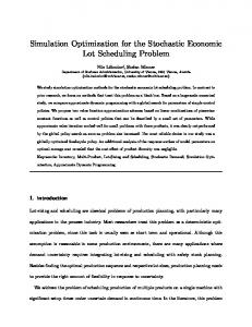
Figure 1 shows a typical example of a structural system loaded by multi-correlated processes. A framed steel structure is given loaded due to wind. This wind was measured at 18 points in a wind tunnel in recent experiments [1]. From this measurement, 240 time series with discrete data exist for the points representing 10 minutes storm events. These data are given in 4096 values, so the sampling time is δt = 0.14648 sec. The wind data can be applied to framed steel structures of any dimensions subject to the condition that the dimension ratio is equal.
wind load 5
6
7
F10 F 11
F9
F8
F7
F5 F6
8
9
10
11
12
F12 F13
13
F14
14
F4
4
15
F15
F3
3
16
F16
F2
2
17
F17
F1
1
18
F18
Fig. 1. A framed steel structure with multi-correlated loading
Stochastic Structural Optimization for Dynamic Load Processes
3
The model for the loading is based on ideas coming from system theory. Both the loading and the structural system are modeled in a state space representation. The wind load can be considered as colored noise. If the load were a white noise it would be easy to compute statistical information of the response of the structure. The idea, therefore, is to reduce the colored noise to white noise, this sort of filter is called a shaping filter. By connecting the shaping filter with a model for the structural system, e.g. a finite element model, a combined filter is established, having white noise as input and the displacements of the structure as output, where the correlation characteristics of the loading are retained. 5
5
4
4
3
3
2
2
1 0
20
20
10
10
4
4
2
2
1 0
500
1000
1500
2000
2500
0
-1
-1
-2
-2
-3
-3
-4
-4
-5
-5
0
0
500
1000
1500
2000
2500
0
0
0 500
1000
1500
2000
2500
-10
-10
-2
-2
-20
-20
-4
-4
Shaping Filter
Structural Filter
S1{A1,B1,C1,D1}
S2{A2,B2,C2,D2}
Input:
Colored Noise,
Output:
White Noise
e.g. Wind, Waves
Displacements, Stresses
Fig. 2. Combination of the shaping filter with the mechanical system The mathematical representation of the shaping filter is given by the following equations:
z1 (t ) = A1 ⋅ z1 (t ) + B1 ⋅ w(t ) f (t ) = C1 ⋅ z1 (t ) + D1 ⋅ w(t )
(1)
Here, the vector f represents the wind load process being the output of the shaping filter and the vector w is the white noise input process. The number of output channels is p and the number of input channels is q. The order of the shaping filter is n. The number n has to be determined. The vector f has the dimension (px1), w is (qx1) und z, the state space variable of the filter, is (nx1). The number of input channels q can be chosen to be equal to the number of output channels p. This continuous representation of the shaping filter has the disadvantage that it is not well suited for the identification of the filter matrices in the multi-correlated case. Because the data of the loading or the correlation functions, respectively, are given in discrete form, a discrete representation has the advantage of being better suited for the use of powerful numerical methods. The representation in discrete form can be written as follows:
4
Heinrich Weber et al.
z k +1 = A 1d ⋅ z k + B1d ⋅ w k
(2)
f k = C1d ⋅ z k + D1d ⋅ w k
The matrices of the continuous time system can be computed from the matrices of this discrete time system. 2.2
Identification of the shaping filter matrices by means of the SVD
The basis for the identification of the shaping filter matrices are the correlation functions of the load processes. A so-called Hankel matrix is composed by means of the sample values:
H1 =
( δt )
( 2 δt )
( 2 δt )
( 3 δt )
( 3δt ) �
( 3δt ) �
(3)
Each submatrix of a discrete time step has the dimension (pxp), for the example here (18x18). The order of the Hankel matrix can be determined from the correlation functions. Usually it is sufficient to use some hundreds of values representing the significant correlation length. If 200 of the 4096 correlation values are used, the matrix has the dimensions (1782x1782). The Hankel matrix can be represented in terms of the system matrices A1d and C1d, and by a matrix M1d which is necessary for the determination of B1d. The Hankel matrix can be decomposed into a column matrix
~ GT :
~ P and a row matrix
2 C1d M1d C1d A 1d M1d C1d A 1d M1d 2 C1d A 1d M1d C1d A 1d M1d H1 = 2 C A M 1d 1d 1d C 1d C A ~ ~ 1d 1d 2 = = P ⋅ GT A 1d M1d A 1d M1d 2 ⋅ M 1d C A 1d 1d �
�
(
�
(4)
)
An appropriate mathematical tool for this task is the singular value decomposition (SVD). By this, the Hankel matrix H1 is decomposed into the three matrices U, Σ and VT:
H1
=
U
⋅
⋅
VT
(1782x1782 ) (1782x1782 ) (1782x1782 ) (1782x1782)
(5)
Stochastic Structural Optimization for Dynamic Load Processes 100
100
10
10
1
1
0,1
0,1
0,01
0,01
1E-3
1E-3
1E-4
1E-4
1E-5
1E-5
1E-6
1E-6
1E-7
1E-7
1E-8
1E-8
1E-9
1E-9
1E-10
1E-10
1E-11
1E-11
1E-12
1E-12
5
1E-13
1E-13 0
500
1000
1500
Fig. 3. Singular values for measured data The matrices U and VT are orthogonal matrices in the real number domain, the matrix Σ is a diagonal matrix with the singular values of the Hankel matrix on the main diagonal. Figure 3 shows a curve of singular values for measured data ordered by their amount. Although it can be seen that there are some large singular values at the beginning and many small singular values at the end, no steep descent between these two regions can be identified here. In contrast to this, conventionally a steep descent is prominent for simulated data. A signal space and a noise space can be separated. That is the reason why the method is called subspace method [3]. A determination of the rank has to be performed. The matrix Σ has the following shape:
σ1 σi =
≈0 ≈ 0 �
(6)
The rank n results from the number of singular values that is regarded as being the significant part. If n = 18 is chosen, the Hankel matrix can be described by the ~ ~ matrices P und G T as follows:
=
H1
U red
⋅
⋅
red
Vred
T
(1782x1782) (1782x18) (18x18) (18x1782)
(
⇔ H1 = U red ⋅ ~ ~ ⇔ H1 = P ⋅ G T
red
)⋅ (
red
⋅ Vred
T
)
(7)
~ ~ The matrices C1d and M1d are given by P (1:p,1:n) and G T (1:n,1:p). The ~ matrix A1d can be determined from by extracting two submatrices from P :
6
Heinrich Weber et al.
~ ~ P1 = P(1 : m − p,1 : n ) ~ ~ P2 = P( p + 1 : m,1 : n )
(8)
where m is the size of the Hankel matrix. Then matrix A1d is computed as the ~ ~ product of the pseudo-inverse of P1 and P2 :
~ ~ A1d = P1+ ⋅ P2
(9)
The basis for the determination of matrix B1d is the discrete time Lyapunov matrix equation which connects the system matrices A1d and B1d with the covariance matrix Pzz,d of the shaping filter:
[
]
[
]
[
]
E z ⋅ z T = A1d ⋅ E z ⋅ z T ⋅ A1d + B1d ⋅ E w ⋅ w T ⋅ B1d T
⇔ Pzz ,d = A1d ⋅ Pzz ⋅ A1d + B1d ⋅ T
T
(10)
I T ⋅ B1d δt
The solution of this equation is given by the infinite sum: ∞
i Pzz,d = ∑ A1d B1d i =0
I ~ ~ T i T B1d A1d ≈ G T ⋅ L−1 ⋅ G δt
(11)
~ This infinite sum can be approximated by means of the matrix G T and a socalled Toeplitz matrix L. This matrix L has the following shape:
0 (δt ) (2 δt ) L= (kδt ) (max δt )
T (δt ) 0
T (2 δt ) T (δt )
(δt )
0
T (kδt ) �
T (max δt ) �
�
T (max δt − δt )
�
�
�
�
�
(max δt − δt ) �
0
(12)
The order of this Toeplitz matrix can be chosen. Hereby, the solution is so much the better the more information of the correlation functions is used. This way of computing the covariance matrix Pzz,d has the advantage that it is very robust and is working always. The disadvantages are that the solution is only an approximation and the accuracy is dependent on the size of the Toeplitz matrix. Since the inversion of the Toeplitz matrixis required the computation can be quite time-consuming. If 200 values of the correlation functions are used and 18 channels exist, the Toeplitz matrix has the dimension (3600x3600). Customarily, the solutions are reasonable. Another problem is the determination of matrix B1d by means of the discrete time Lyapunov equation. Due to the fact that the order of the filter n is usually larger than the number of channels q, the matrix B1d is not quadratic with the T dimension (nxq). To determine matrix B1d from B1d ⋅ B1d it is mandatory that
(
)
Stochastic Structural Optimization for Dynamic Load Processes
7
the rank of the matrix is q. The suitable tool for finding the rank again is the singular value decomposition. An alternative way to compute matrix B1d is the solution of a Riccati equation for the covariance matrix Pzz,d, using some algebraic relations of the system matrices. This way is described in [4]. This approach is very fast compared with the solution using the Toeplitz matrix. Unfortunately the solution of the Riccati equation is not always stable, sometimes even bad or wrong solutions are found. 2.2
Results of the shaping filter generation
First, a shaping filter for the wind loading of a framed steel structure has to be computed. The considered structure is illustrated in Figure 1. The wind load is given by multi-correlated processes measured at 18 points of the structure. Each process is sampled by 4096 discrete data. From these time series the average correlation functions are computed. In total 18x18=326 correlation functions are defined. From these original correlation functions the shaping filter is computed using 200 of the 4096 values of each function in the Hankel matrix. Consequently, the matrix has the dimension (1782x1782). The order of the shaping filter is chosen n = 18.
Φ7−3 (t )
Φ3−3 (t )
0,14
0,02
0,12 0,10
0,00
0,08
-0,02
0,06 -0,04 0,04 -0,06
0,02
-0,08
0,00 -0,02 0
200
400
600
800
1000
-0,10 0
200
Φ12−3(t )
400
600
800
1000
800
1000
Φ16−3 (t ) 0,002
0,002 0,000
0,000
-0,002 -0,004
-0,002
-0,006 -0,008
-0,004
-0,010 -0,012 0
200
400
600
800
1000
-0,006 0
200
400
600
Fig. 4. Comparison of original and identified correlation functions
8
Heinrich Weber et al.
Since the number of channels is 18 as well all system matrices are quadratic. This is very unusual, but it is very advantageous for the numerical stability of the computations. In common, the order of the system n has to be chosen larger than the number of channels p. The comparison between the original functions and the identified functions, however, shows that the resulting curves are sufficiently good, see Figure 4.
3
Combining shaping filter and mechanical model
Of central interest are the responses of the structure due to the loading, or statistical information about these responses, respectively, because the loading is stochastic. The amplitudes of the structural responses are less interesting. Important is the probability density function with its shape and parameters. To get this information, the shaping filter, which describes the loading, is combined with the structural model. This structural model is given by the equation of motion:
Mx 2 ( t ) + Dx 2 ( t ) + Kx 2 ( t ) = f ( t )
(13)
Eq. (13) can be transformed into a state space equation such that both the shaping filter and the structural model have the same form:
x 2 0 x = − M −1K 2
I x 2 0 ⋅ + ⋅f − M − 1D x 2 M −1
z 2 = A 2 ⋅ z2 + B2 ⋅ f �
(14)
The filter for the structure describes a continuous time system while the shaping filter is developed in the discrete time domain. For this reason, a transformation of the shaping filter matrices into continuous time matrices is necessary. One possible transformation is the bilinear transformation:
2 −1 ⋅ (I + A1d ) ⋅ (A1d − I ) δt 4 −1 C1 = ⋅ C1d ⋅ (I + A1d ) δt
A1 =
B1 =
4 −1 ⋅ (I + A1d ) ⋅ B1d δt
D1 = D1d − C1d ⋅ (I + A1d ) ⋅ B1d
(15)
−1
Here, A1, B1, C1, D1 are the continuous time matrices. By a combination of the two filters for the loading and for the structure a combined system is obtained which has white noise as input and the responses of the structure as output. The connection is given by the colored noise f(t): x 2 0 x = − M − 1 K 2 z1 0
I 0 − M −1D M − 1TC1 0 A 1
z G = A G ⋅ z G + BG ⋅ w ( t )
x 2 x + 2 z1
0 M − 1TD w (t ) 1 B1
(16)
Stochastic Structural Optimization for Dynamic Load Processes
9
In Eq. (16) the matrix T connects the loaded points of the system with the degrees of freedom of the structure. As mentioned above, statistical information about the response of the structure is required for a design of a structure with regard to fatigue. To describe the probability density functions of the structural displacements or stresses, respectively, a computation of the statistical moments of the displacement, the speed and the acceleration processes makes sense. By these statistical moments an analytical description of the functions is provided without a time consuming cycle counting method like the rainfall method [5]. The variances of the displacement and the speed processes are given directly by solving the Lyapunov equation of the entire system:
A G Pz G z G + Pz G z G A GT + B G B GT = 0
(17)
Here, the variances are in the covariance matrix of the total system PzG zG on the main diagonal. This approach of finding statistical information for stochastic loads is called the covariance analysis. It is very efficient because the time history integration to get the responses of a structure and, by this, statistical results is replaced by solving only a simple algebraic matrix equation. In particular, the covariance analysis associated with the analytical cycle counting method replaces the whole computation in the micro time domain as mentioned in chapter 1. By the analytical description of the stress amplitudes a damage accumulation rule can be applied and the reliability of the structure can be computed.
4
Optimization with respect to reliability The optimization task with respect to reliability is given in the following way:
min X
{ f (X, Y, Z( t ) ) g (X, Y, Z ( t ) ) ≤ 0 }
(18)
Here, f (X , Y , Z( t ) ) is the optimization criterion, e.g. the cross-section or the cost of a structure. The vector X comprises the optimization variables, e.g. cross section variables, the vector Y describes the random variables, e.g. material or load variables, and the vector Z(t) includes the random processes, e.g. the wind load process. g (X , Y , Z( t ) ) ≤ 0 denotes the optimization constraints, in our case the reliability of the structure. Most important are efficient methods, as explained in chapter 1. Unfortunately, both the optimization and the computation of the reliability are numerically extensive if good and accurate results are needed. A solution in different steps is therefore advantageous. In a first run an approximate solution is estimated. Here, it is most important that the used methods are fast. In a second step the optimum is computed using more accurate methods. Both the methods for the optimization and for the reliability computation can be changed.
10
Heinrich Weber et al.
Client
ProblemServer Problem definition
Optimization server Control Optimization method
Fig. 5. Client-Server concept Finally, in a third step the result of step 2 has to be controlled and improved by using most precise methods, e.g. a simulation method for the reliability computation. Subsequently, only very few iterations have to be performed for the optimization because of the already good start vector. The optimization is based upon a variety of optimization methods where the practical solution makes use of a client-server concept. An existing optimization server which provides different optimization methods is used via a CORBA-based connection [6]. This has the advantage that existing optimization programs can be used. In the same way a reliability server is to be implemented which provides different methods for the computation of the reliability. Also the design for stochastic dynamic load processes may be implemented by a problem server. In the latter case, the client only provides the graphical user interface and controls the run of the different steps. The client-server concept in general has the additional advantages that different servers can be implemented on different computers. By this, it is possible to use the best available platform for the time-consuming parts. Even a distribution of systems connected by the internet is allowed. It must be pointed out that the dynamic structural analysis which has to be carried out in each step of the optimization run only consists of the covariance analysis, i.e. of solving the Lyapunov equation. The identification of the shaping filter, described in chapter 2, which is very time-consuming because of the singular value decomposition of the Hankel matrix and the inversion of the Toeplitz matrix, must only be performed a single time in advance to the optimization run (cp. Figure 6). As a consequence, the dynamic structural analysis is performed in a very efficient way as part of the whole problem. More expensive are the optimization and the computation of the reliability.
4
Summary and Conclusion
In this paper ways and means are discussed for designing structures loaded by dynamical multi-correlated processes. In particular, the model for the loading is explained in detail. In this context, the Singular Value Decomposition is a powerful tool for the identification of multi-correlated load processes. Dynamic stochastic computations are very complex. As a consequence efficient methods are most important. The covariance method fulfils the requirement of
Stochastic Structural Optimization for Dynamic Load Processes
11
efficiency in an appropriate fashion. It provides statistical parameters for the description of the pdf of stress amplitudes. Because of its efficiency the method is best suited for reliability based optimization purposes. In addition, the optimization should be separated into consecutive steps of increasing accuracy to further improve the performance.
Identification of the shaping filter
Next Iteration
Optimization Covariance analysis
Reliability computation
Optimum found
Fig. 6. Optimization strategy
5 [1]
References
Schuëller, G.I. 1999 Computational Stochastic Mechanics – Recent Advances, ECCM’99, European Conference on Computational Mechanics [2] Kasperski, M. & Koss, H.H. & Sahlmen, J. 1996. Beatrice Joint Project: Wind action on low-rise buildings. Part 1: Basic information and first results, J. Wind Eng. Ind. Aerodyn. (64), pp.101-125. [3] van Overschee, P. & De Moor, B. 1997. Subspace Identification for Linear Systems, Kluwer Academic Press [4] Aoki, M. 1987. State Space Modeling of Time Series, Springer-Verlag [5] Bouyssy, V. & Naboishikov, S.M. & Rackwitz R. 1993. Comparison of analytical counting methods for Gaussian processes; Structural Safety (12), pp.35-57. [6] Baitsch, M. & Lehner, K. & Hartmann, D. 1999 A CORBA Based Universal Optimization Service, 1st ASMO UK/ISSMO Conf. on Engineering Design Optimization, pp. 233-240, MCB University Press, Bradford, UK