Apr 4, 2006 - Crystals appeared in 1-3 days and grew to full size (approx. 100 x 20 x 20 µm) in one .... In rapid succession, a boar bristle was touched to the source droplet and ... using vacuum grease to initiate hanging-drop crystallization.
Streak Seeding Automation Using Silicon Tools CUCS-015-06 Atanas Georgiev1 , Sergey Vorobiev2 , William Edstrom2 , Ting Song3 , Andrew Laine3 , John Hunt2 , Peter Allen1 Department of Computer Science1 / Biological Sciences2 / Biomedical Engineering3 Columbia University, New York, NY 10027 {atanas,allen}@cs.columbia.edu, {vorobiev,edstrom,jfhunt}@biology.columbia.edu, {al419,ts2060}@columbia.edu April 4, 2006
Abstract This report presents an approach to automation of a protein crystallography task called streak seeding. The approach is based on novel and unique custom-designed silicon microtools, which we experimentally verified to produce results similar to the results from traditionally used boar bristles. The advantage to using silicon is that it allows the employment of state-of-the-art micro-electro-mechanical-systems (MEMS) technology to produce microtools of various shapes and sizes and thatit is rigid and can be easily adopted as an accurately calibrated end-effector on a microrobotic system. A working prototype of an automatic streak seeding system is presented, which has been successfully applied for protein crystallization.
1
Introduction
Structural Genomics projects are aimed at determining the three-dimensional structures of the profuse amount of proteins to help developing new generation of therapeutic drugs for cure of human diseases. Despite the recent impressive achievements in the high-throughput (HTP) protein crystallography, there are still several bottlenecks, which hold up the large-scale X- ray structure pipeline. One of the biggest obstacles
1
is a production of the high-quality crystals suitable for data collection and structure solution by the modern HTP software. In pilot studies of Phase 1 of the Protein Structure Initiative (PSI), the Northeast Structural Genomics Consortium (NESG) showed that from January 2002 till October 2005 out of 365 homogenous monodisperse purified proteins 113 yielded crystals and only 95 protein crystals were suitable for structure determination and PDB submission. Similar crystallization and structure determination success rates were reported by other Structural Genomics consortia. Some of that loss can be alleviated by crystal optimization techniques including variation of pH, chemical environment, protein/precipitant concentration ratio, temperature, or seeding. For example, the NESG data showed that many of the proteins that crystallize poorly can be streak seeded to yield better diffractionquality crystals that in turn result in resolved protein structures. As another example, researchers utilized streak seeding to go from microcrystals to larger diffraction-quality crystals to attain the structure of LIR2 [8]. Enhancing throughput and increasing success rates is vital for the structural biology community to progress to solving more challenging structures. Seeding is one methodology to enhance crystal quality with challenging proteins. The protein structure initiative, started by the NIH [6] in 1999 and extended into Phase 2 in 2005, accelerated the development of a diverse set of technologies for high-throughput protein production and 3-D structure determination. Many parts of the high-throughput pipeline have been either fully automated or have benefited by the introduction of robotic and automation technologies. However, streak seeding remains a technique that has not been automated. Yet, the task plays an important role in the pipeline as part of overcoming the bottleneck of obtaining diffraction-quality protein crystals. Streak seeding is not a difficult task but requires attention and concentration and takes up valuable time from crystallographers and lab technicians. An automated solution would free up most of this time. Automation also minimizes variability that exists between researchers and even from one seeding to another when the task is performed manually. Minimizing variability translates into greater reproducibility as well as more successful outcomes. The streak seeding procedure appears to be simple and straightforward and as such an easy target for automation. However, it presents significant technical challenges. First, obtaining reliable sensory feedback at the microscale is difficult. Existing micro- and nano-force sensors, for example, have a short operating range for which they need to be tuned and many are still in the experimental stage. Second, the detection of
2
the presence and the locations of protein crystals are challenging problems. Computer vision methods have been suggested and are still being improved [2, 7]. Finally, conventional materials used for streak seeding, such as various types of whiskers, hairs, and bristles, are too soft and flexible and would require sophisticated tracking and visual servoing methods. This report describes the automation and advancement of the streak seeding methodology to overcome the rate-limiting barrier of obtaining diffraction-quality crystals. We propose the use of silicon-made microtools in place of the prevalently used hairs, whiskers or bristles. We describe the manufacturing process of the microtools and present experiments demonstrating that they produce comparable results. The advantage of using silicon is twofold: it allows utilizing existing state-of-the-art micro-electro-mechanical systems (MEMS) technology to manufacture microtools of various desired shapes and sizes, and it is a rigid material that is easy to incorporate as an accurately calibrated end-effector into a microrobotic system. We have demonstrated the latter by building an autonomous streak seeding prototype system, which we also describe here.
2
Materials and Methods
2.1
Silicon Microtools
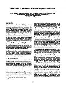
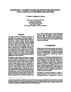
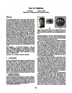
The automatic streak seeding procedure that has been developed is based on custom-made microtools called microshovels fabricated from a single-crystal silicon wafer (Fig. 1). The microshovels were designed and drawn using the AutoCAD software package (Audodesk). More than 30 different types of microshovels were designed which differed in the shape and the size or their tooltips. The tooltip shapes (Fig. 2) were also conceived with an additional application in mind — crystal mounting [4]. The sizes of the fabricated microshovels range from 50 to 280 µm in length, from 7 to 40 µm in height, and 300 µm in width, because these dimensions cover the expected range of protein crystal sizes we would manipulate. The square notches at the bottom of the tool stem (Fig. 1, left) encode the shape and the size of the tip so that the microshovels can be easily distinguished by eye or an automatic reading device. The manufacturing process began with transferring the CAD design onto a 100 x 100 mm quartz photomask. Then a front-side photo-lithography was performed on a silicon wafer, part number 4A0120DSP/300 obtained from Montco Silicon Technologies, Inc, double-side polish, orientation h1-0-0i, 100 ± 0.5 mm diameter and thickness (which translated to the tool width) of 300 ± 25 µm. The wafer was coated with 3
Figure 1: A sample microshovel (left) and a number of microshovels during fabrication from a 100mm diameter silicon wafer (right)
Figure 2: Two different forms of silicon microshovels: design number 0 (left) and design number 17A (right) AZ4620 photoresist, spun in a centrifuge and baked to achieve a uniform coating layer of approximately 10 µm on each side. One side (the front) was exposed to the pattern from the photomask and developed using AZ400K developer. Next, the back side of this wafer was bonded to a larger sacrificial silicon wafer (double-side polish, 150 mm diameter and 625 mm thickness) and the package was processed with deep reactive ion etching (DRIE) leaving the microtools only adherent to the larger wafer. Finally, the microshovels were detached and cleaned up from the bond and the photoresist in an acetone bath.
2.2
Protein purification and crystallization
Expression and purification of Haemophilus influenzae hypothetical protein HI1161 and Xanthomonas campestris hypothetical protein XCC2852 (NESG targets IR63 and XcR50, respectively) was carried out as part of the established high-throughput protein production pipeline of the NESG using previously published methods [1, 3] (crystal structure of shikimate dehydrogenase). Preliminary crystallization trials were performed using the hanging drop vapor diffusion method at 18◦ C using Crystal Screens 1 and 2 and the PEG-Ion Screen from Hampton Research (Laguna Hills, CA). After optimization of the crystallization conditions, XCC2852 crystals useful for structure determination grew
4
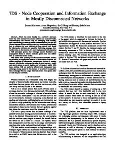
Figure 3: The CARESS prototype workstation for protein crystal streak seeding over a reservoir solution containing 1.6 M (NH4)2SO4, 100 mM NaCl, 100 mM Hepes, pH 6.5. In the case of HI1161, optimization involved streak seeding from slowly-forming crystal clusters. Crystals of HI1161 suitable for X-ray data collection grew over reservoir solutions containing 8-8.5% PEG 3350 (w/v), 0.2 M KFormate. Crystals appeared in 1-3 days and grew to full size (approx. 100 x 20 x 20 µm) in one week. The structures were solved using multiwavelength anomalous diffraction, refined using standard techniques, and deposited in the PDB under accession codes 1O0I for HI1161 (1.70 ˚ A resolution) and 1TTZ for XCC2852 (2.11 ˚ A resolution).
2.3
Streak Seeding Robot
Traditional streak seeding is a procedure that requires close human attention and that has a great deal of variability between different researchers and even between different experiments conducted by the same researcher. It also takes up valuable time from researchers who have to perform the task manually. Because of this, our research has focused on the automation of this procedure. We have created a prototype robotic system, called CARESS (Columbia Automated Robotic Environment for Streak Seeding), which can autonomously perform streak seeding on 96-well plate covers. CARESS (Fig. 3) is based on an MP-285 micropositioner made by Sutter Instrument, which is a Cartesian robot with three degrees of freedom (DOF), a work space of approximately 16 cubic centimeters and
5
Figure 4: An example showing streak seeding of six droplets on a 96-well Neuroprobe plate coversheet. Shown on the left is the droplet with the source crystals on a 22 mm plastic coverslip. The microbridge behind it contains water for cleaning the tool. translational resolution as good as 40 nm in each direction. The micropositioner holds and operates a streak seeding tool (e.g. the silicon microshovels discussed earlier) as its end-effector. It has zero backlash and its fine-grain motion control is used when high positioning accuracy is needed such as when the tool needs to touch the small source crystals. Here is where the rigidity of the silicon becomes very useful, as softer and more flexible materials would greatly reduce the positioning precision of the calibrated system. For faster and larger-scale motion, we use a motorized Prior ProScan stage which has 2 DOF of horizontal motion and a large enough working range to process a 24- or a 96-well plate. The stage is mounted on a model SZX12 optical microscope manufactured by Olympus, which provides a total magnification between 8.4x and 108.0x and is used to observe the work. Live video feedback of the work is captured and fed to a generic personal computer (PC) with a 2.6 GHz CPU and 1 GB RAM by a camera mounted on the microscope. It runs custom software developed as part of the CARESS system, which processes the video stream to analyze the scene and controls the motion of the micropositioner and the stage accordingly. CARESS is currently designed to work with the hanging drop method, seeding from source crystals in a drop on a small coverslip (e.g. 22 mm plastic coverslips for Linbro plates) to destination drops on a coversheet for a 96-well plate (e.g. from NeuroProbe, Inc. or Molecular Dimensions, Ltd). At the beginning of the automated streak-seeding procedure (Fig. 4), the user places on the stage the slide with the protein crystals used as a seed source, the coversheet of the 96-well plate containing the target protein droplets 6
(a)
(b)
(c)
(d)
(e)
(f)
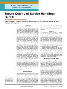
Figure 5: Steps of the streak seeding procedure: (a) initial view of the seeding crystals; (b) detected crystals (in white); (c) tool touching crystal number 1; (d) tool touching crystal number 2; (e) locating the center of the target droplet; (f) streaking through the target droplet where the growth of new crystals will be seeded, and a microbridge with water used for cleaning the seeding tool. The system then proceeds autonomously. First, it moves the stage to position the coverslip with the source crystals under the microscope and takes an image of the crystals (Fig. 5a). Next, a software component identifies the locations of the crystals (Fig. 5b) based on an edge detection algorithm applied to the image, followed by morphological cleaning and binary thresholding operations. The software selects two distinct positions identified as crystals and directs the tool to touch each of them (Fig. 5c,d). Two crystals are used in order to ensure against a rare chance of misdetection of one of them by the image processing software. After that, the streaking action is performed on a number of deposited protein droplets (usually an entire row) on the coversheet for the 96-well plate. The stage is moved so that each circular well region is consecutively centered in the field of view of the microscope. Another image processing component locates where the 7
protein droplet was deposited within that region (Fig. 5e). Finally, the tool is moved through the located droplet (Fig. 5f). For technical details of the image processing components and the system, we refer the reader to [5].
2.4
Crystallization Experiments
XCC2852 crystals were used for optimization of the optical detection algorithm. The streak seeding experiments shown below were conducted on the HI1161 protein. Different proteins were used for optimization and experiments in order to demonstrate that once set up, the system can perform on other proteins as well. Two types of experiments were performed: manual and robotic, both using the hanging drop method. For the manual experiments, the seed source was a droplet on a 22 mm coverslip containing threemonth-old HI1161 microcrystals. The plastic coverslip from the source plate was turned over to expose the microcrystals for seeding. In rapid succession, a boar bristle was touched to the source droplet and then streaked through a freshly prepared target droplet of protein solution mixed with an equal volume of reservoir solution on a clean air-dusted 22 mm coverslip. In a parallel operation, a silicon microshovel was touched to a different source droplet and then streaked through a different target droplet on the coverslip. Additionally, a control droplet was prepared in an identical manner, except that no streak seeding was performed. All coverslips were then flipped over on top of wells pre-filled with reservoir solution and sealed using vacuum grease to initiate hanging-drop crystallization. For the robotic experiments, the seed sources were crystal-containing droplets on 22 mm coverslips that were grown in the same batch as those used for the manual experiments, but the target droplets were located on the surface of a Molecular Dimensions’ HT-96 CrystalClene coversheet. The system was set up and run as described section 2.2 above. After the robot completed the streak seeding, the coversheet was flipped over on top of a Greiner BioOne 96-well plate with wells pre-filled with reservoir solution.
3
Results and Discussion
The results from the manual streak seeding experiment after a 24-hour incubation period are shown in Figure 6. No nucleation was observed in the control droplets (Fig. 6, left) without streak seeding. Lines of microcrystals tracing the trajectory of the boar bristle (Fig. 6, middle) or the microshovel (Fig. 6, right) are clearly visible after manual streak seeding, with the line produced using the microshovel being slightly
8
Figure 6: Manual streak seeding results for the HI1161 protein: control case (left), boar bristle (center), and silicon microshovel (right) wider than that produced using the boar bristle. The results of the seeding done by CARESS after a 24-hour incubation period are shown in Figure 7. As in the case of manual seeding, no nucleation was observed in the control droplets (Fig. 7a,b). Figure 7c-f shows droplets with microcrystals growing after robotic seeding. In an experiment designed to assess the repeatability of the system, 16 out of 16 wells were successfully seeded and none of the four control wells had crystals. The system’s processing speed is currently about 6.5 wells per minute. Speed has not been optimized, because this first prototype is a proof-of-concept implementation aimed at demonstrating that a fully automated instrument can perform the procedure accurately and reproducibly. In the next iteration of the system, we are working to increase the performance by using faster hardware and optimizing the motion control. We are further planning to outfit the system with liquid dispensing capabilities so that the deposition of the protein droplets on the plate cover sheet is also done automatically to reduce dehydration during setup. An interesting question for further research is the effect the shape of the microshovel might have on the quality of the results, if any. The microshovel manufacturing process allows for great flexibility in designing their shapes and sizes. Microtools of different shape, size and thickness can be made just as easily and tested to empirically determine the optimum set of parameters for the given task.
4
Conclusions
An automatic approach to streak seeding has been presented based on using novel silicon- made microshovels in place of the traditional tools such as various types of hairs, whiskers or bristles. A fabrication process for the microshovels has been developed, which is based on MEMS technology and allows for great flexibility
9
(a)
(b)
(c)
(d)
(e)
(f)
Figure 7: Results of the robotic streak seeding using silicon microshovels: (a)-(b) two control cases without seeding; (c)-(f) four robotically seeded wells in the design in terms of both shape and size. It has been demonstrated that the silicon microshovels produce comparable results to boar bristles when used for streak seeding. Finally, a robotic prototype system has been presented, which is based on the microshovels and is capable of streak seeding 96-well plates in approximately 15 minutes, demonstrating the viability of this streak seeding technology.
Acknowledgements This work was supported by grants to the Northeast Structural Genomics Consortium from the Protein Structure Initiative of the National Institutes of Health (NIGMS-P50-GM62413 and NIGMS-U54GM074958). We would like to thank Phillip Manor for his assistance and Gaetano Montelione, Thomas Acton, and Rong Xiao for providing protein samples.
10
References [1] T. B. Acton, K. Gunsalus, R. Xiao, L. Ma, J. Aramini, M. C. Baran, Y. Chiang, T. Climent, B. Cooper, N. Denissova, S. Douglas, J. K. Everett, C. K. Ho, D. Macapagal, P. Rajan, R. Shastry, L. Shih, G. V. T. Swapna, M. Wilson, M. Wu, M. Gerstein, M. Inouye, J. F. Hunt, and G. T. Montelione. Robotic cloning and protein production platform of the Northeast Structural Genomics Consortium. Methods in Enzymology, 394:210–243, 2005. [2] E. D. Angelini, Y. Wang, and A. F. Laine. Classification of micro array genomic images with brushlet analysis and neural networks. The Workshop of Genomic Signal Processing and Statistics (GENSIPS), Baltimore, MD, 2004. [3] J. Benach, I. Lee, W. Edstrom, A. P. Kuzin, Y. Chiang, T. B. Acton, G. T. Montelione, and J. F. Hunt. The 2.3-A crystal structure of the Shikimate 5-Dehydrogenase Orthologue YdiB from Escherichia coli suggests a novel catalytic environment for an NAD-dependent Dehydrogenase. Journal of Biological Chemistry, 278(21):19176–19182, 2003. [4] Atanas Georgiev, Peter K. Allen, and William Edstrom. Visually-guided protein crystal manipulation using micromachined silicon tools. In Proc. IEEE/RSJ Int. Conf. on Intelligent Robots and Systems, IROS’04, September 2004. [5] Atanas Georgiev, Peter K. Allen, Ting Song, Andrew Laine, William Edstrom, and John Hunt. Microrobotic streak seeding for protein crystal growth. In Proc. of Robotics: Science and Systems, Cambridge, MA, June 2005. [6] U.S.
National
Institutes
of
Health.
The
Protein
Structure
Initiative.
Online:
http://www.nigms.nih.gov/psi, 2004. [7] K. Saitoh, K. Kawabata, S. Kunimitsu, H. Asama, and T. Mishima. Evaluation of protein crystallization states based on texture information. In Proc. IEEE/RSJ Int. Conf. on Intelligent Robots and Systems, IROS’04, pages 2725–2730, Sendai, Japan, September 2004. [8] B. E. Willcox, L. M. Thomas, T. L. Chapman, A. P. Heikema, A. P. West Jr., and P. J. Bjorkman. Crystal structure of LIR-2 (ILT4) at 1.8A difference from LIR-1 (ILT2) in regions implicated in the binding of the human cytomegalovirus class I MHC homolog UL18. BMC Struct. Biol, 2(1):6–15, 2002. 11