Aug 9, 2017 - Paul Bounker; Kevin Hope; John Kaniarz; Dennis Bergin. 5d. PROJECT NUMBER. 5e. .... Propagation, COST 231-Walfish-Ikegami (COST-WI).
2011 NDIA GROUND VEHICLE SYSTEMS ENGINEERING AND TECHNOLOGY SYMPOSIUM ROBOTIC SYSTEMS (RS) MINI-SYMPOSIUM AUGUST 9-11 DEARBORN, MICHIGAN
STREAMING VIDEO MODELING FOR ROBOTICS TELEOPERATION Paul Bounker Kevin Hope John Kaniarz CASSI/GVR RDECOM-TARDEC Warren, MI
Dennis Bergin Allied Forces Solutions Vienna, VA
ABSTRACT Most of the current fielded Unmanned Ground Vehicle (UGV) functionality is dependent on the ability to drive the UGV using tele-operation technology. In addition, a large number of payloads require tele-operation to perform the mission function. Tele-operation technology is dependent on providing the operator streaming video, which is reliant on radio capabilities along with video format, resolution and compression routines. There have been Army efforts to perform real-time network modeling as part of Program Executive Office-Integration (PEO-I). These are primarily related to the passing of C2 tactical information from vehicle to vehicle. Ground Vehicle Robotics (GVR) has funded a ‘proof of principle’ effort that culminated in a demonstration performed in February, 2011. This effort modeled the impact of latency, packet/data loss and distorted signal on streaming video being sent from a virtual UGV to the Operator Control Unit (OCU). These distorted signals, cause loss of vehicle control. The initial capability will allow for tradeoff analysis of radios, waveforms and antennas in performing tele-operation and payload control of manipulator arms in various rural and urban environments. This paper will discuss the tradeoffs, architecture and design of the system in support of the February, 2011 demonstration along with potential follow-on activities and capabilities.
INTRODUCTION The Robotics Systems Joint Project Office (RS JPO) and TARDEC Ground Vehicle Robotics (GVR) have defined wireless communications as a key technology enabler for Unmanned Ground Vehicle (UGV) functionality. Most of the current fielded UGV functionality is dependent on the ability to drive the UGV using tele-operation technology. In addition a large number of payloads require tele-operation to perform the mission function. Tele-operation technology is dependent on providing the operator streaming video, which is reliant on radio capabilities along with video format, resolution and compression routines. Field testing of radios, waveforms and antenna‟s can be costly and time consuming. Weather and environment play a large role in wireless communications both of which are difficult if impossible to control in live testing. Modeling and Simulation provides the controllable and repeatable environment needed for radio, antenna and
waveform tradeoff studies. The ability to model wireless and wired communications technologies has existed for quite some time. Most of this has focused on the optimal placement of antennae on vehicles for maximum performance, which is typically performed non-real-time. A real-time capability is needed to provide the user a model of a realistic image to determine the specific performance of a given radio, antenna and bandwidth to evaluate performance of a specific military mission. Joint Ground Robotics Enterprise (JGRE) has decided to fund the further enhancement of the initial architecture defined in this paper to include additional features and technologies starting in FY11. PURPOSE There have been Army efforts to perform real-time network modeling as part of the FCS program. These are primarily related to the passing of C2 tactical information
UNCLASSIFIED: Dist A. Approved for public release
Form Approved OMB No. 0704-0188
Report Documentation Page
Public reporting burden for the collection of information is estimated to average 1 hour per response, including the time for reviewing instructions, searching existing data sources, gathering and maintaining the data needed, and completing and reviewing the collection of information. Send comments regarding this burden estimate or any other aspect of this collection of information, including suggestions for reducing this burden, to Washington Headquarters Services, Directorate for Information Operations and Reports, 1215 Jefferson Davis Highway, Suite 1204, Arlington VA 22202-4302. Respondents should be aware that notwithstanding any other provision of law, no person shall be subject to a penalty for failing to comply with a collection of information if it does not display a currently valid OMB control number.
1. REPORT DATE
3. DATES COVERED 2. REPORT TYPE
11 AUG 2011 4. TITLE AND SUBTITLE
5a. CONTRACT NUMBER
STREAMING VIDEO MODELING FOR ROBOTICS TELEOPERATION
5b. GRANT NUMBER 5c. PROGRAM ELEMENT NUMBER
6. AUTHOR(S)
5d. PROJECT NUMBER
Paul Bounker; Kevin Hope; John Kaniarz; Dennis Bergin
5e. TASK NUMBER 5f. WORK UNIT NUMBER
7. PERFORMING ORGANIZATION NAME(S) AND ADDRESS(ES)
8. PERFORMING ORGANIZATION REPORT NUMBER
U.S. Army TARDEC ,CASSI/GVR,6501 E.11 Mile Rd,Warren,MI,48397-5000
#22049
9. SPONSORING/MONITORING AGENCY NAME(S) AND ADDRESS(ES)
10. SPONSOR/MONITOR’S ACRONYM(S) 11. SPONSOR/MONITOR’S REPORT NUMBER(S)
12. DISTRIBUTION/AVAILABILITY STATEMENT
Approved for public release; distribution unlimited. 13. SUPPLEMENTARY NOTES 14. ABSTRACT
Most of the current fielded Unmanned Ground Vehicle (UGV) functionality is dependent on the ability to drive the UGV using tele-operation technology. In addition, a large number of payloads require tele-operation to perform the mission function. Tele-operation technology is dependent on providing the operator streaming video, which is reliant on radio capabilities along with video format, resolution and compression routines. There have been Army efforts to perform real-time network modeling as part of Program Executive Office-Integration (PEO-I). These are primarily related to the passing of C2 tactical information from vehicle to vehicle. Ground Vehicle Robotics (GVR) has funded a ?proof of principle? effort that culminated in a demonstration performed in February, 2011. This effort modeled the impact of latency, packet/data loss and distorted signal on streaming video being sent from a virtual UGV to the Operator Control Unit (OCU). These distorted signals, cause loss of vehicle control. The initial capability will allow for tradeoff analysis of radios, waveforms and antennas in performing tele-operation and payload control of manipulator arms in various rural and urban environments. This paper will discuss the tradeoffs, architecture and design of the system in support of the February, 2011 demonstration along with potential follow-on activities and capabilities. 15. SUBJECT TERMS 16. SECURITY CLASSIFICATION OF:
17. LIMITATION OF ABSTRACT
a. REPORT
b. ABSTRACT
c. THIS PAGE
unclassified
unclassified
unclassified
18. NUMBER OF PAGES
19a. NAME OF RESPONSIBLE PERSON
7
Standard Form 298 (Rev. 8-98) Prescribed by ANSI Std Z39-18
UNCLASSIFIED
Proceedings of the 2011 Ground Vehicle Systems Engineering and Technology Symposium (GVSETS)
from vehicle to vehicle in Battalion or larger size scenarios. The Communications Effects Server (CES) was developed to support PEO-I, in network performance evaluations. CES provides a model of the time and any or all associated losses of data in sending tactical messages across the battlefield. While this modeling is important for overall situational awareness, it does not provide the necessary functionality for tele-operation and payload control. Radio antenna modeling for best placement on vehicles is performed by CERDEC; this modeling is however, not real-time and would not be able to properly stimulate an Operator Control Unit (OCU). Work on modeling of the radio, antenna and waveform impacts on streaming video is something that needed further attention.
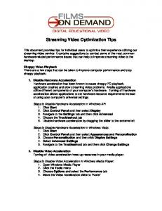
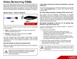
Lab sensors along with other models will be used. The overall architecture is shown in Figure 1.
Leveraging Existing Capabilities TARDEC is using the same tool (QualNet) that is being used to model network communications by PEO-I. This has advantages as TARDEC has acquired the PEO-I CES, based off of QualNet, and which has current models for JTRS, Enhanced Position Location Reporting System (EPLRS) and SINgle Channel Ground and Airborne Radio System (SINCGARS) radios. In, addition many of the radios and waveforms that this tool can evaluate have relatively low TRL levels and thus, purchasing them and integrating with existing OCU and UGVs can be costly and time consuming. These radio and waveform models are being used to create a streaming video model that can stimulate the OCU, which can then be used to drive a virtual UGV around a virtual world. ARCHITECTURE This effort models the latency, packet/data loss, distorted signal and jamming of radio waveforms on functions such as tele-operation and payload manipulator arm control loops. Modeled results are displayed on an Operator Control Unit (OCU) as distorted signals, loss of vehicle and manipulator control, etc. In addition, the ability for supervised autonomy based on waveform signal capabilities and properties in different environments can be addressed. Rural and urban terrains will be addressed to include, at a minimum, elevation changes, foliage and power lines. The ability to measure and evaluate signal strength for tele-operation in a building clearing scenario will be developed. Different building materials such as wood, steel and concrete; and their effects on various radios will be modeled. Different weather conditions and their effects on radio waveforms and signal strengths will be measured. At a minimum wind, rain and snow will be modeled. The Modeling Architecture for Technology, Research and EXperimentation (MATREX) tools and compliant models such as Night Vision
Figure 1: System Architecture QUALNET/CES The prototype of the communications model was developed with QualNet Developer 5. QualNet Developer 5 is a commercial product offered by Scalable Network Technologies (SNT), and is ultra high-fidelity network simulation software that predicts wireless, wired and mixedplatform network and networking device performance. It is designed for engineers who do research, testing, network design, modeling & simulation, and hardware and software development. QualNet is a comprehensive set of tools with all the components for custom network modeling and simulation, and is designed to link seamlessly with modeling/simulation applications and live networks. QualNet, was selected because, ultimately, the Streaming Video Model will be used to investigate tohe previously specified radio and waveform models developed under the CES architecture. CES is based on QualNet, and was developed to address the Brigade Combat Team Modernization (BCTM) needs of modeling accurate communications. CES is a modular and scalable software representation of a mobile ad-hoc communications network running on a single or multi-processor hardware platform. It provides BCTM communications effects in real time and faster than real time to support live, virtual, constructive, and force-on-force BCTM-related simulation events. The
Streaming Video Modeling for Robotics Teleoperation
UNCLASSIFIED Page 2 of 7
UNCLASSIFIED
Proceedings of the 2011 Ground Vehicle Systems Engineering and Technology Symposium (GVSETS)
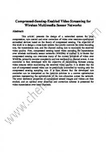
primary function of the CES is to return message completion rate and end-to-end latency back to the force-on-force simulator when queried. The very same functionality needed by the Streaming Video Model. Future development will include porting the prototype to the CES architecture. The QuaNet framework was used to configure and integrate various models for the simulation. These models included radio, waveform, wireless network, routing, urban propagation, terrain and weather. In addition, the effort included designing and developing an application to bridge the interface of tthe OCU IG to the actual simulation. The OCU Communication (Comms) Interface, as shown in Figure 2, is an Application Layer program integrated into QualNet. The program interacts with the (QualNet) network and communications simulation engine using the QualNet External Interface API, and also interacts with the OCU IG via another external socket interface. The QualNet provided External Interface API allows QualNet to interact with external entities such as other programs or physical devices.
Figure 2: OCU/Comms Interface The main function of the OCU Comms Interface Application is to interface with the simulation engine, retrieve various statistics and provide them to the OCU IG simulator. The main statistics to be gathered and reported back to the OCU IG include aggregate counts, mean and variance for packet throughput jitter, latency, and dropped packets. The statistics are updated and transmitted across the OCU/Comms Interface at a rate of 1/sec. COMMUNICATIONS MODEL PROTOTYPE To develop the communications model prototype, various models were configured, developed within or integrated into the QualNet framework. These models included radio, waveform, wireless network, routing, urban propagation, terrain and weather. The QualNet wireless library was utilized. This library included functionality for modeling the wireless propagation, antennae, the Physical Layer, MAC Layer, Network Layer, and routing. In addition, the QualNet Urban Propagation Library was used to bring in urban propagation models such as the COST 231-Hata Propagation, COST 231-Walfish-Ikegami (COST-WI) Propagation Model, and the Okumura-Hata Propagation Model Propagation, as well as other propagation models.
The prototype utilized the automatic propagation feature, which allowed the QualNet simulator to select appropriate path-loss models based on the node location and urban terrain features. Different path-loss models are used according to their locations, with respect to obstacles in the propagation path. The automatic propagation feature of QualNet allows selection of different model(s) for each source-destination pair and changes the models dynamically as the node positions change. Specific details of the models are described. The wireless channel modeled after IEEE 802.11g 2.4 GHz operation at a data rate of 24 Mbps. The radios were modeled after the Ubiquiti Super Range 2 (SR2) radio, which is used in the Pacbot system. The model accounted for specific parameters of the radio such as , data rates, tx channel width, tx power range, rx sensitivity range, and a packet reception model. The antenna were modeled after the Ubiquiti 2.4GHz AirMax 2x2 MIMO Base station Sector Antenna (Hi-Gain Airmax Sector 2G-120-16). The model represented an omnidirectional antenna, and accounted for specific parameters of the antenna such as frequency range and gain, height, cable loss and connection loss. The simulated data connections were modeled after realistic video and control channels. The data included three data connections. The first connection represented low priority, video data from the SUGV to the OCU at 1.922 Mbps constant bit rate (CBR). The second connection represented higher priority, control data from the OCU to the SUGV at 409.6 Kbps variable bit rate (VBR). The third connection represented equally high priority status data form the SUGV to the OCU at 49.6Kbps VBR.
STREAMING VIDEO MODELING For operational relevance it was necessary to modify the virtual image generation to the OCU in a similar manner to what occurs in the „live‟ operational system. The overall process is to capture the video frames, compress them into a Moving Pictures Experts Group (MPEG) video stream, corrupt the stream based on signal quality, then decode and display the corrupted video. In our system the scene is drawn using the OpenSceneGraph (OSG) library, and the video is created using FFmpeg, an open source video library. Corrupting the Data Via a simple User Datagram Protocol/Internet Protocol (UDP/IP) based network link to QualNet, various signal quality statistics are received. The key parameters are packets dropped and packet latency. Because of the nondeterministic rate of updates from QualNet, approximately 3hz, the packets dropped and packet latency statistics are used in a simplistic packet dropping algorithm. This
Streaming Video Modeling for Robotics Teleoperation
UNCLASSIFIED Page 3 of 7
UNCLASSIFIED
Proceedings of the 2011 Ground Vehicle Systems Engineering and Technology Symposium (GVSETS)
algorithm is a modified memcpy command that drops packet-sized blocks of bytes until an internal dropped packet count equals the current count from the simulation. In addition, the timestamp of the frame is increased based on the calculated network latency. Finally, the corrupted stream and time stamp are written to an object for decoding. OSG Rendering to Texture While Open Scene Graph (OSG) has support for displaying video streams, it does not support recording its output into a Moving Pictures Experts Group (MPEG) video stream. It is necessary for this process to be performed manually, using raw image data as an intermediary. OSG‟s Camera object supports rendering to texture, and OSG‟s Image object provides the copying and conversion of a texture on the video card into a raw Red Green Blue Alpha (RGBA) image in system memory. FFmpeg provides a swScale library to resize and convert the RGBA image into the Luma UltraViolet (YUV) 4:2:2 format required for an MPEG stream. To have an OSG camera render to texture, a sequence of steps must be performed. The first step is to create an Image object and allocate a buffer for the raw image. This method requires a width, height, pixel format, and type. The width and height should match the target resolution of the video stream. Matching the resolution of the image to the video stream is not required, but a mismatch will result in some stretching or “squishing” of the image, as well as a performance penalty. Next, the camera is set to render to a frame buffer object, the image is attached as the color buffer and a post-draw callback is created and registered to allow the camera to grab the frame when rendering is complete. Care must be taken in converting the frame into the correct format due to the flexibility of the Scale library which has many options to allow conversion between various formats. The scaling library requires a context to hold its settings and a frame to hold the converted data. When creating a context a RGBA pixel format is used, and the format of the destination is copied from the codec object. The frame object requires a buffer to store the frame. Finally, the image object is converted into a frame. Once converted, the frame is passed to the encoder. However, to keep the rendering pipeline from stalling, the frame is pushed onto a queue for processing in another thread, and a timestamp is created to support the simulation of network latency. Creating the Video Stream The basic process for creating a video stream is to use avcodec_encode_video, which uses an AVCodecContext to convert the AVFrame into a raw buffer. Normally this buffer
is converted into an AVPacket and either sent to a file or streamed via the Internet; in our software we corrupt the buffer before creating the packet and send the packet directly to the decoder. While this is a simple process, configuring the context is one of the most involved parts of using FFmpeg. A complete video context has a format, a video stream, configuration, buffers, and a header. A video format object is created with default settings and a video stream that uses the codec id from the format object. In this stream, the settings such as resolution and data rate, of the simulated video camera are configured. Since some encoders do not use all of the features in the MPEG specification, unused features are disabled. Real time streaming video requires bframes to be disabled. A b-frame can copy picture data from both future frames and previous frames which improves compression. However, this adds much latency because a large number of frames have to be buffered, and thus for the simulation b-frames are disabled. Lastly, a stream header is created to initialize the stream, and a copy of the codec context is made for use in the decoding process. Decoding and Displaying the Frame Decoding and displaying the frame repeats all the previously outlined capture and encode steps in reverse order. Decoding the stream requires another codec context. This codex can be copied from the encoding context after it is created, but before it is used. Create a frame in the same fashion as the one in the conversion process and decode the packet into the frame. This frame, with its timestamp is pushed onto a queue for use by the rendering thread. In OpenSceneGraph, an additional camera is created for displaying, an image object, and a geometric object is used to hold a full screen rectangle textured with the image. A pre-draw callback that checks the front of the frame queue to see if it is time to display a new frame, is then created. The scale library is used to convert and copy the frame into the image object. The conversion context is created with the source and destination formats reversed from the context used in the OSG to FFmpeg conversion. Once the callback returns OpenSceneGraph will internally copy the image data to video memory, and display it. The scale library is used to convert and copy the frame into the image object. The conversion context is created with the source and destination formats reversed from the context used in the OSG to FFmpeg conversion. Once the callback returns, OpenSceneGraph will internally copy the image data to video memory, and display it. This is the final step in the IG simulation.
Streaming Video Modeling for Robotics Teleoperation
UNCLASSIFIED Page 4 of 7
UNCLASSIFIED
Proceedings of the 2011 Ground Vehicle Systems Engineering and Technology Symposium (GVSETS)
backward and pivot. The joystick can also be used to control the arm of the robot. The WMI also provides a video feed from the simulated SUGV. This represents a perfect world with no delay or video degradation.
Encoding the Frame To encode a frame use the codex encode_video context. This function takes a buffer, and the converted frame in as parameters. A copy of the encoding context is needed for decoding the video later. This copy is made with the codex copy context function. UGV MODELING To fully provide operational relevance the complete work cycle from the OCU is modeled in a similar manner to what occurs in the „live‟ operational system. This includes the mobility of the platform and complete virtual environment, which are described in the following sections. Common Controller The unmanned ground vehicle (UGV) simulation was provided by TARDEC‟s Common Controller (CC) Simulation. The CC was developed to demonstrate controlling multiple robotic assets with a single operator control unit (OCU). The CC was developed for the Robotic Vehicle Control Architecture (RVCA) to support the Brigade Combat Team Modernization (BCTM) effort. The simulated robotic units can be of similar or different types. Currently the CC has the ability to simulate a TALON, small unmanned ground vehicle (SUGV), and an unmanned aerial system (UAS). Mobility Models As part of the support to CC and the RS JPO, the mobility models were built for both the SUGV and TALON, by TARDEC. These models were built from scratch to include forward, reverse, and pivot maneuvers. Collision detection was also developed and integrated into the mobility model. The mobility and overall functionality of the SUGV and TALON models were verified and validated in the summer of 2010. SMI Controls A user uses a mouse to interact with the CC‟s war fighter machine interface (WMI). The user is able to select and load a predefined scenario file that specifies how many of each type of robotic asset will be available in the simulation. Once loaded, the user selects and takes control of a robotic asset. A USB joystick is then used to control the robot, which allows the user to make the robot move forward,
Database In an effort to reduce cost, time and risk, a terrain database, previously developed by PEO-I (formally PMFCS), was used. The terrain database covers a combination of Ft Bliss in Texas and White Sands Missile Range (WSMR) in New Mexico and was developed to support the PM FCS FY08 Spin Out test events. In 2009, the Embedded Simulation Team from TARDEC modified the Ft Bliss/WSMR database to include a military operations in urban terrain (MOUT) site, in support of the MRAP SIL. Since a majority of missions for SUGVs and TALONs are in urban environments, this made the modified Ft Bliss/WSMR database a perfect fit for the planned “proof of principle” demonstration. In addition, the Ft Bliss/WSMR database is available in three needed formats of Open Flight, Digital Terrain Elevation Data (DTED), and OneSAF Terrain Format (OTF). External Interface The CC software has a Distributed Interactive Simulation (DIS) interface. The DIS interface is used to send out EntityState Protocol Data Units (PDUs) of the simulated SUGV. The EntityState PDUs contain important information about the simulated SUGV including its location and orientation. This information is used by the QualNet software to model the radio signal between the OCU and SUGV. The information is also used by the streaming video model to draw the proper simulated video feed. PROTOTYPE RESULTS The basic scenario setup for the demonstration was to position the simulated SUGV inside of the MOUT site and position the OCU outside of the MOUT site. Both the OCU and SUGV were simulated in the QualNet software. The OCU was positioned at a certain distance away from the SUGV so that minimal movement of the SUGV inside the MOUT site would cause some radio data packets to be dropped between the SUGV and OCU. The SUGV was driven around the inside of the MOUT site and as the signal strength between the OCU and SUGV would change, the streaming video model would display the resulting video degradation. As previously described, various statistics were retrieved from the simulation and provide to the streaming video model. The retrieved statistics consistently matched the status of the communications link between the
Streaming Video Modeling for Robotics Teleoperation
UNCLASSIFIED Page 5 of 7
UNCLASSIFIED
Proceedings of the 2011 Ground Vehicle Systems Engineering and Technology Symposium (GVSETS)
OCU and SUGV depending on the locations. While terrain and, propagation and path loss were being modeled, the analysis focus on basic link state and communications affects on the streaming video, as a “proof of principle.” It is expected that future work will utilize the system for higher fidelity simulation and analysis.
FUTURE PLANS We are working towards meeting RS JPO requirements for FY2011. Issues or concerns will be shared with the RS JPO and adjustments to schedule and functionality will be carried out when agreed to by all parties to be in the best interest of DoD UGV efforts. Rural and urban terrains will be addressed to include at a minimum elevation changes, foliage and power lines. The ability to measure and evaluate signal strength for tele-operation in a building clearing scenario will be developed. Diverse building materials such as wood, steel and concrete; and their effects on various radios will be modeled. Different weather conditions and their effects on radio waveforms and signal strengths will be measured. At a minimum wind, rain and snow will be modeled. Further experimentation on different weather and atmospheric conditions will be explored. Interest has been shown by SPAWAR and NAVEODTECH to share in this work. This current architecture and functionality will be shared with SPAWAR and NAVEODTECH. Along with developed Qualnet radio models and other developed capabilities, TARDEC simulation environment for distributed simulation capabilities and modeling of streaming video impacted by radio models will be provided upon request and necessary agreements put in place. This may be of use to SPAWAR or NAVTECHEOD for support of their programs. There may be interest in supporting JIEDDO by modeling IED jamming properties at the Navy Integrated Battlespace ARena (IBAR) facility. IBAR may also be interested in modeling the cell phone capabilities in detonating IEDs. As autonomy continues to increase, additional capabilities such as teleoperated target acquisition and engagement in a reduced communications environment can be studied and worked on with appropriate degradation to video and sensor images. Teaming algorithms could be developed and assessed in different and degraded communications environment. Placements of repeaters in different buildings and/or terrains could be assessed to provide their operational impacts. Testing can be enhanced by modeling of test range facilities for best placement of communication towers for overall range coverage.
This capability gives the RS JPO and others a current powerful simulation environment to perform tradeoffs on existing and future radios, antennas, waveforms, etc. as it relates to tele-operations using streaming video to control the drive and payload features of UGVs. This effort will support autonomous & tactical behaviors development in particular for such things as supervised autonomy. Developers will be able to use these tools in concert with semi-autonomous behaviors to determine what mission capabilities are possible with different levels of autonomy as UGV technology moves from the semiautonomous to fully autonomous behaviors. This effort will support manipulation technologies development by allowing for tradeoff analysis on different radio and waveform technologies as they relate to ease of robotic manipulation and mobile manipulation to expedite the transition and integration of corresponding robotic technologies to enhance the current fielded systems. This effort will support interoperability by assisting the RS JPO Interoperability Profile (IOP), comms WIPT in performing planned tradeoff analysis of different radios and waveform communications channels and hardware in the performance of relevant robotics missions. This effort will support technology, transition and transformation by facilitating the integration of radios and waveform communications technologies into existing and developing programs into interface technologies. This will assist in the sharing of information for such capabilities as fusion and positioning.
REFERENCES [1] SNT, “QualNet Family Reference”, www.scalablenetworks.com, 2010. [2] SNT, “QualNet-5.0.2-UsersGuide”, www.scalablenetworks.com, 2010. [3] SNT, “QualNet-5.0.2-Wireless-ModelLibrary”, www.scalable-networks.com, 2010. [4] SNT, “QualNet-5.0.2-UrbanPropagation-ModelLibrary”, www.scalable-networks.com, 2010. [5] SNT, “Interface Design Description (IDD) for Communication Effects Server (CES) 7.0. Rev N”, December 22, 2010.
CONCLUSION
Streaming Video Modeling for Robotics Teleoperation
UNCLASSIFIED Page 6 of 7
UNCLASSIFIED
Proceedings of the 2011 Ground Vehicle Systems Engineering and Technology Symposium (GVSETS)
**Disclaimer: Reference herein to any specific commercial company, product, process, or service by trade name, trademark, manufacturer, or otherwise, does not necessarily constitute or imply its endorsement, recommendation, or favoring by the United States Government or the Department of the Army (DoA). The opinions of the authors expressed herein do not necessarily state or reflect those of the United States Government or the DoA, and shall not be used for advertising or product endorsement purposes.**
Streaming Video Modeling for Robotics Teleoperation
UNCLASSIFIED Page 7 of 7


![video streaming - Ustream [PDF]](https://m.moam.info/img/260x300/video-streaming-ustream-pdf_6496b7c4098a9e46588b4605.jpg)