Jul 18, 1984 - rock that forms in calcite gouge sheared at sub-seismic sliding velocities, the role ... De monsters bestaan uit natuurlijk, klei-rijk breukmeel en.
STRENGTH, STABILITY, AND MICROSTRUCTURE OF SIMULATED CALCITE FAULTS SHEARED UNDER LABORATORY CONDITIONS SPANNING THE BRITTLE-PLASTIC TRANSITION
B. A. Verberne
Utrecht Studies in Earth Sciences No. 90
Members of the dissertation committee: Prof. Dr. Einat Aharonov Earth Science Institute, The Hebrew University of Jerusalem Jerusalem, Israel Prof. Dr. Frederick M. Chester Dept. of Geology and Geophysics, Texas A&M University College Station (Texas), United States of America Prof. Dr. Martyn R. Drury Dept. of Geosciences, Utrecht University Utrecht, The Netherlands Prof. Dr. Brian Evans Earth Resources Laboratory, Massachusetts Institute of Technology Cambridge (Massachusetts), United States of America Prof. Dr. Changrong He Institute of Geology, China Earthquake Administration Beijing, People’s Republic of China This research was carried out at: High Pressure and Temperature Laboratory Dept. of Geosciences, Utrecht University Budapestlaan 4, 3584 CD, Utrecht The Netherlands State Key Laboratory of Earthquake Dynamics Institute of Geology, China Earthquake Administration Yard #1, Huayanli, Chaoyang district, Beijing P. R. of China.
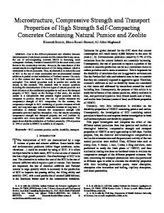
ISBN/EAN: 978-90-6266-402-3 Copyright © 2015 Berend Antonie Verberne All rights reserved. No part of this publication may be reproduced in any form, by print or photo print, microfilm or any other means, without written permission by the publishers. Printed by: CPI Koninklijke Wöhrmann Cover image: Fibrous (mirror-like) slip patch formed at 1 µm/s. SE micrograph, HFW = 10.2 µm.
Strength, stability, and microstructure of simulated calcite faults sheared under laboratory conditions spanning the brittleplastic transition
Sterkte, stabiliteit, en microstructuur van calciet breukgesteenten, gedeformeerd onder laboratorium condities die de overgang van bros naar ductiel bestrijken (met een samenvatting in het Nederlands)
Proefschrift ter verkrijging van de graad van doctor aan de Universiteit Utrecht op gezag van de rector magnificus, prof.dr. G.J. van der Zwaan, ingevolge het besluit van het college voor promoties in het openbaar te verdedigen op vrijdag 18 september 2015 des ochtends te 10.30 uur
door
Berend Antonie Verberne geboren op 18 juli 1984 te Halsteren
Promotor:
Prof. dr. C. J. Spiers
Copromotoren:
Dr. J. H. P. de Bresser Dr. A. R. Niemeijer
Dit proefschrift werd(mede) mogelijk gemaakt door financiële steun via beurs #2011-75 toegekend door het Netherlands Research Centre for Integrated Solid Earth Sciences (ISES).
“Sabba danam dhamma danam jinati sabbam rasam dhamma raso jinati sabbam ratim dhamma rati jinati tanhakkhayo sabba dukkham jinati” - Verse 354, Dhammapada (Tanhavagga)
Contents Summary .................................................................................................... 13 Samenvatting .............................................................................................. 19 Chapter I General introduction and aims ................................................................... 25 1.1. Motivation and scope of this study .................................................... 26 1.2. Seismicity in carbonate terrains and deformation processes in calcite rocks .................................................................................. 27 1.3. The earthquake instability and the seismogenic zone ....................... 29 1.4. Rate-and-state friction models ......................................................... 32 1.5. Microphysical models of fault gouge frictional sliding ...................... 35 1.6. Structure and aims of this thesis....................................................... 36 Chapter II Frictional properties of sedimentary rocks and natural fault gouge from the Longmenshan Fault Zone, Sichuan, China ................................... 39 Abstract ................................................................................................. 40 2.1. Introduction ..................................................................................... 41 2.2. Background ...................................................................................... 43 2.2.1. Regional geology and sampling strategy .......................................................... 43 2.2.2. Rate and State dependent Friction laws .......................................................... 44 2.3. Experiments ..................................................................................... 47 2.3.1. Approach and choice of conditions .................................................................. 47 2.3.2. Sample material ................................................................................................ 48 2.3.3. Sample assembly ................................................................................................51 2.3.4. Experimental apparatus ................................................................................... 53 2.3.5. Data acquisition and processing ...................................................................... 53 2.3.6. Experimental procedure ................................................................................... 55 2.4. Results ............................................................................................. 56 2.4.1. Friction coefficient vs. displacement data ........................................................ 56 2.4.2. Dependence of friction coefficient on temperature ........................................ 59 2.4.3. RSF constitutive parameters ............................................................................ 60
2.5. Discussion ........................................................................................ 64 2.5.1. Frictional strength ............................................................................................. 64 2.5.2. Velocity dependence ......................................................................................... 68 2.5.3. Microphysical mechanisms controlling friction ............................................... 71 2.5.4. Implications for the Wenchuan earthquake and LFZ ..................................... 73 2.6. Conclusions ...................................................................................... 76 Appendix 2.A. Simulation of RSF behaviour and scaling relations for quasi-static oscillations at k = kcr ............................................ 79 Acknowledgements ................................................................................. 83 Chapter III Frictional properties and microstructure of simulated calcite-rich fault gouges sheared at sub-seismic sliding velocities ................................. 85 Abstract ..................................................................................................86 3.1. Introduction ..................................................................................... 87 3.2. Methodology ....................................................................................89 3.2.1. Sample materials ............................................................................................... 89 3.2.2. Experimental apparatus ................................................................................... 89 3.2.3. Direct shear testing assembly ........................................................................... 90 3.2.4. Experimental procedure and conditions ......................................................... 93 3.2.5. Data processing and analysis ........................................................................... 94 3.2.6. Sample recovery and microstructure analyses ................................................ 96 3.3. Mechanical results ...........................................................................98 3.3.1. Frictional strength data..................................................................................... 98 3.3.2. Velocity dependence data ............................................................................... 102 3.4. Microstructures ............................................................................. 103 3.4.1. Inspection of samples upon retrieval ............................................................. 103 3.4.2. Optical analysis of thin sections ..................................................................... 104 3.4.3. FIB-SEM and TEM analysis ........................................................................... 107 3.5. Discussion ...................................................................................... 109 3.5.1. Microphysical mechanisms operating in dry and wet samples ...................... 110 3.5.2. Mechanisms controlling the velocity dependence of strength ...................... 112 3.5.3. The role of water and impurities ..................................................................... 114 3.5.4. Geological implications ................................................................................... 118 3.6. Conclusions ..................................................................................... 119 Appendix 3.A. Photomosaics of sheared gouge samples ................................. 122
Appendix 3.B. Correlative light- and electron microscopy .............................. 124 Acknowledgements ............................................................................... 125 Chapter IV Nanogranular principal slip zones in simulated calcite fault gouge sheared at 1 µm/s .......................................................................................127 Abstract ................................................................................................ 128 4.1. Introduction ................................................................................... 129 4.2. Materials & Methods ....................................................................... 131 4.2.1. Samples and direct-shear assembly ................................................................ 131 4.2.2. Mechanical testing procedure & sample recovery ......................................... 134 4.2.3. Data processing ................................................................................................135 4.2.4. Microscopy methods ........................................................................................135 4.3. Results ........................................................................................... 136 4.3.1. Mechanical data............................................................................................... 136 4.3.2. Sample-scale and optical observations ........................................................... 137 4.3.3. (FIB-)SEM analysis......................................................................................... 138 4.3.3.1. General structure of the PSZ .................................................................. 138 4.3.3.2. Internal structure of the shiny patches ................................................. 140 4.3.3.3. Compositional anomalies ...................................................................... 143 4.3.4. TEM analysis: Internal structure of single fibres .......................................... 145 4.3.5. AFM and surface roughness analyses .............................................................147 4.4. Discussion ...................................................................................... 148 4.4.1. Microphysical mechanisms controlling friction ............................................ 149 4.4.2. Formation of the PSZ nanostructures and CPO .............................................155 4.4.3. Comparison with microstructures formed in HVF experiments ................... 157 4.4.4. Origin of carbon-rich phases .......................................................................... 159 4.4.5. Superplasticity in geological materials vs. the present samples ................... 159 4.4.6. Geological implications ................................................................................... 161 4.5. Conclusions ..................................................................................... 161 Appendix 4.A. The Niemeijer-Spiers model ................................................. 163 Appendix 4.B. Calculation of dilatation and compaction rates......................... 165 Acknowledgements ............................................................................... 168 Chapter V Frictional-viscous transition in simulated calcite fault gouge sheared at 20-600°C and implications for seismogenesis in limestones ................. 169
Abstract ................................................................................................ 170 5.1. Introduction .................................................................................... 171 5.2. Background .................................................................................... 174 5.3. Materials and Methods .................................................................... 177 5.3.1. Sample material ................................................................................................ 177 5.3.2. Experimental apparatus .................................................................................. 177 5.3.3. Experimental procedure and conditions ........................................................179 5.3.4. Data acquisition and processing .................................................................... 180 5.3.5. Sample recovery and microstructural analysis .............................................. 185 5.4. Mechanical data ............................................................................. 185 5.4.1. Experiments at constant effective normal stress ........................................... 185 5.4.1.1. Strength-displacement curves ................................................................ 185 5.4.1.2. Effect of temperature on strength .......................................................... 189 5.4.1.3. Behaviour at low displacement rates .................................................... 189 5.4.1.4. Amplitude of stick-slip events ................................................................. 191 5.4.2. Effective normal stress stepping experiments ............................................... 192 5.4.3. Velocity dependence of strength (Γ) .............................................................. 196 5.5. Microstructural observations ......................................................... 199 5.5.1. Microstructures developed at 20° to 200°C ................................................... 199 5.5.2. Microstructures developed at 400° to 550°C ................................................ 201 5.5.3. Microstructures developed at 600°C ............................................................. 204 5.6. Discussion ......................................................................................204 5.6.1. Deformation mechanisms ............................................................................... 205 5.6.1.1. Mechanisms operating at 20° to 200°C ................................................. 205 5.6.1.2. Mechanisms operating at 400° to 600°C .............................................. 206 5.6.2. Microphysical processes controlling steady-state strength and slip stability .............................................................................................. 210 5.6.3. Geological implications .................................................................................. 212 5.7. Conclusions .................................................................................... 214 Appendix 5.A. Construction of deformation mechanism maps for calcite .......... 216 Acknowledgements ............................................................................... 218 Chapter VI Strain rate dependent, frictional-to-viscous transition in simulated calcite fault gouge sheared at 550°C: Implications for the lower boundary of the seismogenic zone ............................................................ 219
Abstract ................................................................................................ 220 6.1. Introduction ................................................................................... 221 6.2. Materials and Methods ................................................................... 224 6.2.1. Sample material............................................................................................... 224 6.2.2. Experimental apparatus ................................................................................. 225 6.2.3. Experimental conditions and procedure ....................................................... 227 6.2.4. Data processing and analyses......................................................................... 230 6.2.5. Sample recovery and microstructural analyses ............................................. 231 6.3. Mechanical results ......................................................................... 232 6.3.1. Experiments at constant effective normal stress ........................................... 232 6.3.2. Effective normal stress stepping experiments ............................................... 233 6.3.2.1. Runs at constant displacement rate (0.1 and 10 µm/s) ....................... 233 6.3.2.2. Experiments employing an interval of slip at v = 100 to 300 µm/s ... 236 6.3.2.3. Shear stress - effective normal stress data ........................................... 237 6.4. Microstructures ............................................................................. 239 6.4.1. Inspection of samples upon retrieval ............................................................. 239 6.4.2. Optical and electron microscopy results ....................................................... 240 6.4.2.1. Microstructure developed at σneff = 50 MPa at v = 0.1 µm/s ............... 240 6.4.2.2. Microstructure developed at σneff = 50 MPa at v = 100 µm/s ............. 241 6.4.3. Grain size data ................................................................................................ 244 6.5. Discussion ...................................................................................... 247 6.5.1. Deformation mechanisms ............................................................................... 247 6.5.1.1. Mechanisms operating at v = 0.1 µm/s ..................................................251 6.5.1.2. Mechanisms operating at v = 10 and 100 µm/s ................................... 252 6.5.2. Role of localization in controlling strength and slip stability ....................... 254 6.5.3. Geological implications .................................................................................. 256 6.6. Conclusions.................................................................................... 256 Acknowledgements ............................................................................... 258 Chapter VII General conclusions and suggestions for further research ....................... 259 7.1. The methods used ...........................................................................260 7.2. Main findings ................................................................................. 261 7.2.1. Effect of temperature on the shear behaviour of calcite(-rich) fault gouges...................................................................................................... 261 7.2.2. Microstructure of calcite gouge sheared at sub-seismic sliding velocities ... 262
7.2.3. Microphysical processes controlling (the velocity dependence of) shear strength .................................................................................................. 263 7.3. Geological implications .................................................................. 265 7.3.1. Implications for seismicity in tectonically-active limestone terrains ........... 265 7.3.2. Implications for the interpretation of natural fault rock microstructures ............................................................................................... 266 7.4. Remaining questions and suggestions for further research ............ 267 7.4.1. Unsolved problems .......................................................................................... 267 7.4.2. Remaining data needs..................................................................................... 269 7.4.3. Broader challenges ...........................................................................................271 References ................................................................................................ 273 Afterword/ Acknowledgements ................................................................ 295 List of publications ................................................................................... 299 Curriculum Vitae ..................................................................................... 300
Summary Destructive earthquakes are commonplace in tectonically-active carbonate-bearing terrains, often leading to major loss of life and severe economic damage. Recent examples include the 2012 Emilia and 2009 L’Aquila sequences in Italy, as well as the devastating 2008 Wenchuan earthquake in China and the 2005 Kashmir earthquake in Pakistan. Efforts to improve seismic risk assessment in such regions require a quantitative understanding of the failure, slip, and healing behaviour of faults in carbonate rocks. However, few relevant data exist. In this thesis, I report the results of an experimental study aimed at filling this knowledge-gap, through experimental investigation of the mechanisms controlling the shear behaviour of simulated fault gouges composed of calcite (CaCO3). To quantify the mechanical behaviour of these materials, saw-cut, direct-shear, as well as rotary-shear experiments were conducted at sub-seismic sliding velocities, under pressure and temperature conditions relevant to earthquake nucleation in the upper and middle crust. To identify the controlling deformation processes, the deformed samples were submitted to correlative microstructural study, across scales ranging from the cm/ mm range down to the nanoscale, using state-of-the-art microscopy methods. In Chapter I, an outline of the motivation and scope of this study is given, including a brief overview of seismicity in limestone and carbonate terrains, and of the phenomenology of fault friction and seismogenesis. Key definitions are summarized, and relevant previous work is discussed. I close by listing the aims of this thesis. Chapter II investigates the frictional properties of samples collected from the region hit by the 2008 Wenchuan earthquake, i.e. from the Longmenshan Fault Zone (LFZ), Sichuan, China. The samples consisted of simulated gouges prepared from limestone (the Xujiahe Limestone), clay-rich clastic sediments, and a clay-rich natural fault gouge recovered from a trenched surface rupture. Friction experiments employed a simulated gouge layer embedded in a saw-cut assembly. This was sheared in an Argon-gas medium, triaxial deformation apparatus, under water-saturated conditions using a pore ware pressure of 20 MPa, at a confining pressure of 53 MPa, at temperatures of 25° to 150°C, and at sliding velocities of ~0.1 to 1 µm/s. While the clay-rich samples were frictionally 13
Summary
relatively weak (friction coefficient µ = 0.4-0.6) and consistently velocity strengthening, the simulated limestone gouge was strong (µ = 0.6-0.7), and showed a transition from velocity strengthening behaviour at 25° and 50°C to velocity weakening at ~100° and 150°C. When applied to faulting in the LFZ region, this implies that the presence of clayrich sediments may have a damping effect upon ruptures propagating from depth, whereas limestones at 5 to 8 km depth may accelerate propagation, producing significant stress drops. The presence of large masses of limestone in the upper-crust may thus enhance seismic hazard. Chapter III focuses exclusively on the frictional properties of simulated gouge prepared from limestone and pure calcite, and on the microscale processes controlling the transition from velocity strengthening to velocity weakening behaviour reported in Chapter II, i.e. at temperatures between 50° and 100°C. The experiments consist of direct shear tests performed in a silicone-oil confining medium, triaxial deformation apparatus, under nominally dry and water-saturated conditions, at 18° to 150°C, at an effective normal stress of 50 MPa, and sliding velocities of 0.1 to 10 µm/s. Wet tests were conducted using a pore water pressure of 10 MPa. Regardless of whether dry or watersaturated, the results resemble the data on simulated limestone gouge presented in Chapter II, though the wet samples showed lower frictional strengths then the dry samples (µ = 0.6-0.7 vs. 0.7-0.8). Both wet and dry runs showed a transition from velocity strengthening to velocity weakening behaviour above ~80 to 100C. All samples developed narrow boundary and inclined, Riedel-type shear bands characterized by a crystallographic preferred orientation (CPO) and an ultrafine grain size of only ~5 to 20 nm in the shear band core. Through-going boundary shear bands accommodated the bulk of the imposed displacement, and thus represent the principal slip zone (PSZ). When split after an experiment, the PSZ becomes exposed, revealing striated, highlyreflective (shiny) surface patches developed within the PSZ shear plane, resembling the ‘mirror slip’ surfaces recently reported to form at co-seismic slip rates (>0.1 m/s). Contrary to recent claims, these results suggest that nanocrystalline, ‘mirror-slip’ surfaces in faults cutting carbonates are not unambiguously indicative of paleoseismic slip. By comparison with previous work it is argued that the observed frictional behaviour is controlled by a mechanism of dilatant granular flow operating in competition with creep-controlled compaction which increases in importance with increasing temperature. Assuming a geotherm of 20-25°C/km, it is argued that the upper cut-off in seismogenesis 14
Summary
in limestone terrains occurs at a depth of ~4 km, consistent with fore- and aftershock hypocentre distributions reported for e.g. the Apennines (Italy). Chapter IV continues with a micro- and nanostructural study of the PSZs reported in Chapter III, including a detailed investigation of the striated, shiny or ‘mirror-like’ slip-surface patches. Imaging of the PSZ micro-/ nanostructure was achieved using focused ion beam - scanning electron microscopy (FIBSEM) and transmission electron microscopy (TEM). Atomic force microscopy (AFM) was used for roughness characterization of the shiny surfaces. The PSZ is shown to consist of a relatively porous, 10 to 50 μm thick, sheet-like volume, composed mainly of rounded, ~100 nm-sized particles or nanospherules that show widespread interparticle neck growth or sintering. The shiny surface patches, on the other hand, consist of dense, planar films composed of aligned chains of nanospherules, or fibres, about 100 nm in width, embedded within the PSZ volume. At the sub-nanospherule scale, the nanofibres consist of ~5 to 20 nm sized calcite crystallites, with their (104) rhomb planes aligned sub-parallel to the shear plane, consistent with the shear band CPO reported in Chapter III. It is argued that a thin (~1-2 nm) aqueous film adsorbed to the ~100 nm nanospherules facilitated intergranular diffusive-mass transfer and neck growth in the PSZ. On this basis, a mechanism of dilatant nanogranular or nanofibre flow with partial accommodation by diffusive mass transport, resembling Ashby-Verrall superplasticity and consistent with the model discussed in Chapter III, is put forward to explain the transition from velocity strengthening to velocity weakening slip seen in simulated calcite gouge above ~80°C. The implication is that nanocrystalline PSZs in calcite faults can produce seismogenic fault friction through a mechanism involving diffusive mass transfer, even at depths in the upper crust where temperatures are generally considered too low to support diffusion at active fault slip rates. In view of numerous recent reports of nanogranular fault surfaces in tectonically-active terrains, I suggest that the proposed mechanism may be generally relevant to upper-crustal seismogenesis. In an attempt to gain equivalent insight into what controls the lower limit of the seismogenic zone in limestone terrains, Chapter V explores the shear behaviour of simulated calcite gouge over temperatures expected to embody the full frictional-toviscous or brittle-plastic transition. Experiments were conducted in a hydrothermal ringshear apparatus at 20° to 600°C, under water-saturated conditions using pore fluid 15
Summary
pressures (Pf) in the range 10 ≤ Pf ≤ 100 MPa. Velocity stepping experiments, performed at an effective normal stress of 50 MPa and employing sliding velocities in the range 0.03 ≤ v ≤ 100 µm/s, showed that the velocity weakening behaviour observed in the preceding chapters at temperatures above 80° to 100°C is maintained up to temperatures of ~550°C. This was frequently associated with regular stick-slip behaviour, showing major stress drops, especially at the higher temperatures and lower sliding velocities employed. A transition back to velocity strengthening behaviour was finally seen at ~600°C. Across the full temperature range explored, the gouge shear strength, measured after ~11 mm of displacement at v = 1 μm/s, varied from ~28 MPa (µ ≈ 0.6) at 20°C, 19 to 23 MPa (µ ≈ 0.4-0.5) at 100° to 550°C, and 29 to 32 MPa (µ ≈ 0.6) at 600°C. Meanwhile, combined velocity-stepping and effective normal stress-stepping tests, conducted using 1 ≤ v ≤ 100 µm/s and 30 ≤ 𝜎𝑒𝑓𝑓 𝑛 ≤ 100 MPa, consistently showed a linear increase of shear stress upon increasing effective normal stress. The microstructure of samples sheared at 20° to 200°C showed the same localized shear band pattern reported to form in samples sheared at 20° to 150°C in Chapter III. However, the microstructures developed at 400° to 600°C show that pervasive, intracrystalline plastic deformation and dynamic recrystallization of the gouge grains also played role, alongside localized boundary slip involving dilatant flow. Continuing the comparison of the shear behaviour observed in simulated calcite gouges with the predictions of the granular flow versus compaction creep model discussed in Chapters III and IV reveals a striking phenomenological consistency. It follows from the experimental data that the base of the seismogenic zone in overpressurized limestones occurs at 13 to 24 km depth, depending on geothermal gradient and degree of pore fluid overpressure. This depth range is consistent with observations of seismicity attributed to the suspected presence of carbonate rocks at depth in the southern Apennines as well as in the Zagros Mountains (Iran). Chapter VI further investigates the processes operating in simulated calcite gouge sheared at conditions near the transition, at 550° to 600°C, from velocity weakening to velocity strengthening behaviour, as established in Chapter V. The experiments reported consist of ring-shear tests performed under water-saturated conditions, at a temperature of ~550°C, at a pore fluid pressure of 100 MPa, at constant sliding velocities of 0.1, 1, 10 and 100 µm/s, and at an effective normal stress that was either fixed at 50 MPa or else sequentially stepped in the range 20 ≤ 𝜎𝑒𝑓𝑓 𝑛 ≤ 140 MPa. When sheared at 0.1 µm/s, gouge strength was found to be insensitive to effective normal stress, and the corresponding 16
Summary
microstructure points to shear dominated by distributed, ductile flow. By contrast, samples sheared at a relatively high sliding velocity (1, 10, or 100 μm/s) all showed a linear increase in shear strength with effective normal stress, verifying frictional behaviour, plus a strongly localized microstructure consisting of a single boundaryparallel shear band cutting a relatively undeformed bulk gouge. Interestingly, the shear band, formed at 100 μm/s at 550°C, showed a similar optical CPO to that formed in samples sheared at 0.1 to 10 μm/s at 20° to 150°C (Chapter III), pointing to a common deformation process inferred to involve oriented attachment of ultrafine (0.1 m/s). Met behulp van eerder werk beredeneer ik dat het wrijvingsgedrag waarschijnlijk bepaald wordt door een mechanisme van dilatante korrelstroming, simultaan opererende met tijdsafhankelijke compactie van het korrelaggregaat. Omdat dit laatste steeds sneller gaat, en dus belangrijker wordt, met verhogende temperatuur, kan een transitie van wrijvingssnelheidsversterking naar wrijvingssnelheidsverzwakking zich voordoen. Voor een typische geothermische gradiënt van 20-25°C/km, impliceren de resultaten dat de bovengrens van de seismogene zone in kalkgesteente op een diepte van zo’n 4 km ligt. Dit is in overeenstemming met observaties van seismische activiteit in tectonisch-actieve gebieden die rijk zijn aan carbonaatgesteenten, zoals bijvoorbeeld in de Apennijnen (Italië). In Hoofdstuk IV ga ik door met een micro- en nanostructureel onderzoek van de hoofdschuifzones of PSZs zoals gerapporteerd in hoofdstuk III, inclusief een detailstudie van de gestrieerde, sterk reflecterende vlakjes. De PSZ is onderzocht met behulp van een gecombineerde ionen/ electronenmicroscoop (een ‘focused ion beam - scanning electron microscope’), een transmissie-elektronenmicroscoop, en een atoomkrachtmicroscoop. De observaties maken duidelijk dat de PSZ een relatief poreus, 10 tot 50 μm dik, plaatachtig volume vormt, wat voornamelijk bestaat uit geronde, ~100 nm grote deeltjes of ‘nanobolletjes’ die onderling vaak gesinterd zijn. Binnen het PSZ volume worden de gestrieerde vlakjes aangetroffen, als dichte films van gelijkgerichtte, ca. 100 nm brede, 21
Samenvatting
ketting-achtige vezels. Intern bestaan de nanobolletjes, en dus de nanovezels, uit ~5 tot 20 nm kleine calciet kristallieten, die met hun (104) kristalvlak (hexagonaal kristalsysteem) min of meer gelijkricht liggen aan het algemene schuifvlak. Aan de hand van de observaties stel ik voor dat massatransport in de PSZ gefaciliteerd is door diffusie via een 1-2 nm dikke, aan het oppervlak van de nanobolletjes geadsorbeerde waterfilm. Aan de hand hiervan wordt vervolgens een conceptueel model gepresenteerd die de transitie van wrijvingssnelheidsversterkend naar wrijvingssnelheidsverzwakkend gedrag van calcietbreukmeellaagjes boven ~80°-100°C, zoals geconstateerd in de voorgaande hoofdstukken, kan verklaren. Het model berust op dilatante stroming van nanobolletjes en –vezels, vergelijkbaar met het model zoals bediscussieerd in hoofdstuk III, en met het klassieke model voor superplastische deformatie van Ashby-Verrall. Een belangrijke implicatie is dat nanokristallijne schuifzones in calcietbreukmeel seismogeen kunnen zijn als gevolg van een diffusieproces, zelfs op diepten waar de temperatuur normaliter te laag is om dit te kunnen activeren. In het licht van talloze recente publicaties die het voorkomen en belang van nanokristallijne breukvlakken in een verscheidenheid van gesteenten in de bovenkorst onderschrijven, suggereer ik dat het voorgestelde mechanisme een toepassing heeft op seismogeen gedrag in het algemeen. Vervolgens, in een poging om een soortgelijk inzicht te krijgen in de processen die een rol spelen rondom de onderlimiet van de seismogene zone in kalkgesteente, onderzoek ik in Hoofdstuk V het wrijvingsgedrag van gesimuleerde calcietbreukmeellaagjes op temperaturen waarvan redelijkerwijs verwacht mag worden dat ze de bros-ductiel transitie
bestrijken.
Experimenten
worden
uitgevoerd
in
een
hydrothermale
ringwrijvingsmachine (ofwel ‘ring shear’), op temperaturen van 20° tot 600°C, onder waterverzadigde omstandigheden met een poriëndruk van 10 tot 100 MPa. Experimenten waarbij de wrijvingsnelheid systematisch en stapsgewijs wordt gevarieerd, 𝑒𝑓𝑓
uitgevoerd bij een effectieve normaalspanning (𝜎𝑛 ) van 50 MPa en gebruikmakend van wrijvingssnelheden tussen 0.03 en 100 µm/s, laten zien dat het snelheidsverzwakkende gedrag boven temperaturen van ca. 80°C zich doorzet tot een temperatuur van ~550°C. Een transitie naar snelheidsversterkend gedrag wordt uiteindelijk gevonden op ~600°C. De schuifsterkte van de laagjes breukmeel, gemeten na ca. 11 mm verplaatsing op een snelheid van 1 μm/s, varieerde van ~28 MPa (µ ≈ 0.6) op 20°C, 19 tot 23 MPa (µ ≈ 0.40.5) op 100° tot 550°C, en 29 tot 32 MPa (µ ≈ 0.6) op 600°C. Experimenten waarin zowel stappen in wrijvingssnelheid (v) als in effectieve normaalspanning worden toegepast, 22
Samenvatting
𝑒𝑓𝑓
gebruikmakende van 1 ≤ v ≤ 100 µm/s en 30 ≤ 𝜎𝑛
≤ 100 MPa, laten zien dat de
schuifsterkte lineair toeneemt met toenemende effectieve normaalspanning, en dus een frictie-proces
vertegenwoordigd.
De
microstructuur
van
de
breukmeellaagjes
gedeformeerd op 20°C tot 200°C word gekenmerkt door een vergelijkbaar patroon van lokalisatie in nauwe schuifzones, zoals gezien in monsters gedeformeerd op 20°C tot 150°C in hoofdstuk III. Echter, op 400°C tot 600°C zijn naast dilatante korrelstroming in een gelokaliseerde, grensparallelle schuifzone ook tekenen van meer homogene deformatie zichtbaar, waaronder intrakristallijne plastische vloei en dynamische rekristallisatie van de grovere breukmeelkorrels. De resultaten laten een opvallende gelijkenis zien met voorspellingen van het eerder aangehaalde model omtrent dilatante korrelstroming met tijdsafhankelijke deformatie, d.w.z. hoofdstuk III en IV. Verder impliceren de resultaten dat de seismogene zone in kalkgesteenten, in een staat van overdruk, zich uitstrekt tot een diepte van ca. 13 tot 24 km. Dit komt overeen met seismiciteit zoals geobserveerd in de zuidelijke Apennijnen, en het Zagrosgebergte in Iran, op diepten waarvan verwacht wordt dat er carbonaatgesteenten aanwezig zijn. Hoofdstuk
VI omvat een onderzoek naar de wrijvingseigenschappen en
microstructuur van gesimuleerde calcietbreukmeellaagjes gedeformeerd op condities rondom de transitie van snelheidsverzwakkend naar snelheidsversterkend gedrag rondom ~550°C tot 600°C, zoals geconstateerd in hoofdstuk V. De experimenten zijn wederom uitgevoerd in de ringwrijvingsmachine, onder waterverzadige omstandigen met een poriëndruk van 100 MPa, op een temperatuur van 550°C, gebruikmakende van constante wrijvingssnelheden van 0.1, 1, 10 en 100 µm/s. De effectieve normaalspanning 𝑒𝑓𝑓
is constant gehouden op 50 MPa, dan wel gestapt in een bereik van 20 ≤ 𝜎𝑛
≤ 140 MPa.
Bij relatief lage snelheid (0.1 µm/s) is de gemeten schuifspanning in minder mate, dat wil zeggen niet-lineair, afhankelijk van de effectieve normaalspanning, indicatief voor ductiliteit, en wordt de microstructuur gekenmerkt door homogene deformatie, typisch voor ductiele vloei. Ter vergelijking, in experimenten op relatief hoge snelheid (1, 10, of 100 μm/s) is de schuifspanning lineair afhankelijk van de effectieve normaalspanning, indicatief voor frictie, terwijl de microstructuur op 100 μm/s gekenmerkt wordt door lokalisatie in één grensparallelle schuifzone. Opmerkelijk genoeg heeft deze schuifzone optische eigenschappen vergelijkbaar met die van de breukmeellaagjes gedeformeerd op 0.1 tot 10 μm/s, bij 20°C tot 150°C, zoals gerapporteerd in hoofdstuk III. De resultaten impliceren ondermeer dat de bros-ductiel transitie in calcietbreukmeel afhankelijk is van 23
Samenvatting
de vervormingssnelheid. Verder laten ze zien dat lokalisatie cruciaal is voor breuksterkte en -stabiliteit, in het bijzonder nabij de ondergrens van de seismogene zone. Tenslotte wordt in Hoofdstuk VI een synopsis gepresenteerd van de voornaamste bevindingen in dit proefschrift en geef ik een overzicht van de implicaties voor seismiciteit
in
kalksteenrijke
gebieden.
Voorname
conclusies
betreffen
het
nanokristallijne karakter van gelokaliseerde zones in calcietbreukmeel, de rol die fysische eigenschappen op de nanoschaal spelen in het nucleëren van aardbevingen, en de brosnaar-ductiel transitie die is geconstateerd met temperatuur en met wrijvingssnelheid. Ik sluit af met een opsomming van onopgeloste problemen, en formuleer ook nieuwe problemen, welke direct volgen uit het gepresenteerde werk.
24
Chapter I
General introduction and aims
25
Chapter I
1.1. Motivation and scope of this study Earthquakes are the result of a sudden release of energy during rapid slip (v > 1 m/s) along geologic fault zones in the Earth’s crust or upper mantle, resulting in the generation of seismic waves that can be highly destructive at Earth’s surface. Throughout history, earthquakes and associated tsunamis have claimed countless lives and caused severe material and economic damage. It is therefore of utmost importance to improve prognoses on the frequency, location, and magnitude of future events. However, this requires sophisticated modelling of earthquake nucleation and dynamic rupture propagation, which in turn requires a fundamental understanding of the failure, slip, and healing mechanisms operative in geologic faults, i.e. of fault rock sliding mechanisms active under in-situ conditions in the Earth. Despite several decades of research on fault friction, our understanding of the material properties of fault rocks and how they control the nucleation of earthquakes, remain poor. Tectonically loaded faults, such as those present along plate boundaries or in depleted gas reservoirs, can exhibit aseismic “creep” without producing earthquakes, or exhibit unstable motion, resulting in slow-slip events or catastrophic failure as the case for earthquakes (see e.g. Scholz, 1998, 2002; Peng & Gomberg, 2010). Seismic fault motion of this type can occur at the lithosphere-scale, such as along megathrust faults in subduction zones (e.g. Hyndman et al., 1997), on a regional scale as is the case for reservoir-induced seismicity (e.g. Talwani, 1997), but also within mm- to cm-scale samples in the laboratory (e.g. Passelègue et al., 2013). The fault zones involved typically show evidence for multi-scale, self-similar behaviour (e.g. Tchalenko, 1970; King, 1983), characterized by strain localization into extremely narrow zones (e.g. Sibson, 2003) composed of nanogranular fault rocks (Power & Tullis, 1989; Chester & Chester, 1998; Chester et al., 2005; Ma et al., 2006; Siman-Tov et al., 2013; Kuo et al., 2014; Collettini et al., 2014). This suggests that the physical properties of fault rocks at the nano-scale may exert a major control on the macroscopic fault sliding properties. To achieve a better understanding of earthquake nucleation processes it is therefore crucial to unravel the key processes that control multi-scale fault slip, starting with a fundamental understanding of the nano- to micro-scale, material physical processes active within fault zones. In this thesis, motivated by the frequency of destructive earthquakes in tectonicallyactive carbonate-bearing terranes, I report the results of an experimental study designed to determine the mechanisms controlling the sliding behaviour of fault rocks composed 26
General introduction and aims
of the dominant carbonate mineral, calcite (CaCO 3). Experiments were conducted using unique triaxial deformation equipment as well as a unique ring shear apparatus, at low sliding velocities (0.01 to 100 µm/s) and under in-situ conditions of pressure and temperature pertaining to upper-crustal seismogenesis. Correlative observations from the visual, cm-scale to the nano-scale, using state-of-the-art methods in microscopy, allowed for imaging and subsequent interpretation of the relevant physical mechanisms active during fault slip. Alongside providing new data, and new insights into the processes leading to seismogenesis, the results lend support to the validity of recent mechanistic models for fault gouge friction. 1.2. Seismicity in carbonate terrains and deformation processes in calcite rocks Carbonate rocks are a class of rock types that are primarily composed of minerals characterized by a divalent cation plus a carbonate anion (CO 32-), such as calcite and aragonite [CaCO3], siderite [FeCO3], or dolomite [CaMg(CO3)2]. The major rock groups of sedimentary origin include limestones and dolostones, which are respectively composed mainly of calcite and dolomite. These rocks typically form as bioclastic calcite deposits, which may later be dolomitized by Mg-rich fluids (e.g. Machel, 2004), or as biochemical calcite or dolomite precipitates in marine or lacustrine environments (e.g. Nichols, 2004). The largest occurrences are platform carbonates, which form as vast marine, mainly calcareous deposits at the margins of the continental shelf (e.g. Wilson, 1975; Nichols, 2004). After diagenesis, and uplift and erosion in the orogenic cycle (see e.g. Twiss & Moores, 2007), such platform carbonate bodies frequently come to form a dominant lithology in tectonically-active terrains such as rifts and the external zones of orogens. It is for this reason that seismicity in carbonate or carbonate-bearing terrains is commonplace. Recent, devastating examples of highly destructive earthquakes in tectonically-active carbonate terrains include the Mw 5.9 2012 Emilia event (Italy – Pizzi & Scisciani, 2012), the Mw 6.1 2009 L’Aquila event (Italy – Chiaraluce, 2012), the Mw 7.9 2008 Wenchuan event (China - Xu et al., 2009; Chen et al., 2013a, b) and the M w 7.6 2005 Kashmir event (Pakistan – Hussain et al., 2009). Some of these earthquakes have relatively shallow hypocentres, as is the case for the first main shock in the Emilia sequence (6.3 km, Pizzi & Scisciani, 2012), or are associated with numerous shallow aftershocks, as observed following the 2009 L’Aquila event (~2 km, Chiaraluce, 2012; Valoroso et al., 2013). Their shallow nature means that they are often particularly damaging, even when the moment 27
Chapter I
magnitude is relatively moderate (Boatwright & Choy, 1986; Ma, 2008; Lee et al., 2009). Knowledge of the lithology of the earthquake host rock at greater hypocentral depths is often challenging, however, in some cases seismicity at ≥15 km depth has been specifically attributed to the presence of carbonate rocks. Examples include earthquakes at 15 km depth in the Zagros mountains of Iran (Nissen et al., 2011, 2014), but also in the southern Apennines, where seismicity at depths of ~18 km is inferred to be due to the stacking of carbonate rocks of the Apulia platform (Boncio et al., 2007). Despite the frequency of destructive earthquakes in tectonically-active carbonate terrains, previous work on the frictional behaviour of carbonate fault rocks is limited (see also Mirabella et al., 2008; Scuderi et al., 2013). Experimental data show that (simulated) calcite(-rich) fault rocks exhibit unusual frictional properties compared with other common sedimentary rock types such as clay stones and sandstones (Ohnaka, 1975; Scuderi et al., 2013; Carpenter et al., 2014; Tesei et al., 2014), and have a tendency to exhibit potentially seismogenic behaviour at relatively shallow, upper-crustal conditions of pressure and temperature (Drennon & Handy, 1972; Olsson, 1974; Ohnaka, 1975). At the same time, calcite(-rich) rocks are well-known to exhibit ductile deformation by mechanisms such as pressure solution and crystal plasticity, at lower pressures and temperatures than generally required for these mechanisms to operate in other upper crustal rock types, such as granite (e.g. Burkhard, 1990; De Bresser, 1991; Spiers et al., 2004; see also Paterson & Wong, 2005). From microphysical modelling and analogue experiments, it is well-known that such time-dependent deformation mechanisms can play an important role in the processes controlling gouge frictional sliding, including those leading to seismogenic fault slip (Chester, 1994; Sleep, 1997; Nakatani, 2001; Bos & Spiers, 2002a, b; Niemeijer & Spiers, 2006, 2007; Den Hartog & Spiers, 2013, 2014). Crystal plasticity or pressure solution processes may therefore offer the key to explaining the unusual frictional behaviour of calcite-rich fault rocks compared with other sedimentary rocks. Combining a) the frequency of seismicity in the carbonate cover of regions such as the Apennines (e.g. Chiarabba et al., 2005, 2014) and Corinth Rift (e.g. Bernard et al., 2006), with b) the atypical, readily unstable frictional character of calcite fault rocks, with c) their tendency to exhibit ductile deformation at shallow crustal conditions, suggests that faults in carbonates may be particularly prone to seismogenic slip at upper crustal depths (e.g. 0 for (inherently stable) velocity strengthening slip and (a-b) < 0 for (potentially unstable) velocity-weakening slip. In the case that (a-b) = 0, frictional sliding is velocity neutral or rate independent. Furthermore, regardless of which evolution law, at steady-state 𝜃̇ = 0, so that 𝜃𝑠𝑠 = 𝐷𝑐 /𝑣. From equation 1.2 it then follows that the magnitude of (a-b) at 34
General introduction and aims
steady-state is given by (𝑎 − 𝑏) = d𝜇𝑠𝑠 /dln(𝑣) (e.g. Marone, 1998a; Scholz, 1998). 1.5. Microphysical models of fault gouge frictional sliding The time-dependent healing and sliding velocity dependent effects of friction are generally explained in terms of creep of asperities or contact junctions characterizing the slider-surface contact or fault plane (Scholz & Engelder, 1976; Dieterich & Kilgore, 1994; Berthoud et al., 1999). Asperity creep or time dependence can result from the operation of Arrhenius-type (thermally-activated) deformation mechanisms such as intracrystalline plasticity, diffusive mass transfer (including pressure solution), or subcritical cracking (Chester & Higgs, 1992; Chester, 1994). For this reason, physical interpretations of the RSF model as discussed above typically rely on a thermally-activated, Arrhenius-type rheology active at the asperity (contact) scale (Chester & Higgs, 1992; Chester, 1994; Sleep, 1997, 2005; Baumberger et al., 1999; Berthoud et al., 1999; Nakatani, 2001; Rice et al., 2001; Noda & Shimamoto, 2010; He et al., 2013; Shimamoto & Noda, 2014). However, RSF descriptions have remained empirical to date, with little physical basis regarding the internal deformation and healing processes active during gouge frictional slip, and without taking internal geometric or microstructural aspects into account (Bos, 2000; Niemeijer, 2006; Niemeijer & Spiers, 2006, 2007; Den Hartog, 2013; Den Hartog & Spiers, 2014; Chen, 2015). Extrapolation to nature, i.e. to slip rates, length scales, pressure-temperature conditions, or other boundary conditions not attainable in laboratory friction experiments, therefore presents a major source of uncertainty in numerical modelling of natural fault motion (for a recent discussion see Ide, 2014). An understanding of the chemical and micromechanical interactions that occur during frictional sliding of granular aggregates, such as fault gouge, requires knowledge of the relevant bulk and intergranular deformation processes, plus a model framework. Bos & Spiers (2002a) for the first time formulated a microphysical model for frictionalviscous flow of halite-phyllosillicate mixtures (simulated fault gouge analogue), at low slip rates (0.05 to 10 µm/s), involving a serial process of slip over phyllosillicate foliae and pressure solution of intervening halite clasts. This provided a theoretical framework that could explain the normal stress sensitive, velocity strengthening behaviour seen in their experiments (see Bos, 2000). In order to explain frictional velocity weakening behaviour seen in experiments on halite-phyllosillicate mixtures sheared at 1 to 13 µm/s, Niemeijer & Spiers (2005, 2006) developed this concept further by incorporating effects of dilatancy at high(er) slip rates. In their model, frictional sliding is described as a 35
Chapter I
granular flow process involving competition between dilatation and intergranular compaction by pressure solution (Niemeijer & Spiers, 2007). Changes in frictional strength and its rate dependence (a-b), with velocity and temperature, are due to changes in their relative contribution to strain-accommodation. The approach employed by Bos & Spiers (2002a) and Niemeijer & Spiers (2007) allows for gouge frictional behaviour to be expressed as a function of effective normal stress, shear strain rate, temperature, and the relevant microstructural parameters or materials properties. Den Hartog & Spiers (2013, 2014) developed the model further, and showed that it can explain frictional velocity strengthening and –weakening in phyllosillicate-quartz mixtures over a wide range of conditions of pressure, temperature, displacement rate, and effective normal stress (see Den Hartog, 2013). The fundamental principle of the model as developed by Niemeijer & Spiers (2006, 2007) rests on the simultaneous operation of (relatively) time-insensitive dilatant processes (e.g. granular flow) and time-dependent creep (e.g. pressure solution, crystal plasticity), within the sheared granular aggregate, the competition between which controls frictional strength and its velocity dependence. An important topic to address remains whether this conceptual model is generally applicable, i.e. whether it can explain the frictional properties of granular media other than halite- or quartz-phyllosillicate mixtures. Since (simulated) calcite gouge is monomineralic, and since the ease of plasticity in calcite, this material is highly suitable for exploring this question. 1.6. Structure and aims of this thesis From the foregoing, it is clear that i) calcite dominated lithologies, such as limestone, form a major constituent of tectonically-active terrains such as rifts and orogens, ii) improved modelling of seismogenesis in tectonically-active carbonate terrains is needed, and iii) little is known about the frictional behaviour of carbonate rocks in general. The research conducted here aims to address these points by providing new mechanical and microstructural data on calcite fault gouge, which will be used to test and calibrate mechanism-based models describing fault frictional behaviour. Shearing experiments are reported that make use of (simulated) calcite(-rich) fault gouge, under (near) in-situ conditions relevant to earthquake nucleation in tectonically-active carbonate terrains, and resultant microstructures are analyzed using the latest techniques in electron microscopy.
36
General introduction and aims
The specific aims of this thesis are: 1.
To determine experimentally the frictional and microstructural properties of (simulated) calcite fault gouge sheared at slip velocities and at pressure-temperature conditions relevant to seismogenesis in the shallow (~≤10 km) crust. The primary focus here is the frictional strength and stability of calcite fault gouges compared with gouges prepared from other common upper-crustal rock types, as well as the microstructural features developed during shear.
2.
To determine the deformation mechanisms involved, and how these control shear resistance and stability of fault slip. This aim targets the physical properties of calcite fault gouge expected to be relevant to nucleation of earthquakes.
3.
To
qualitatively
compare
the
experimental
results
and
sheared
gouge
microstructures with a micromechanical model for shear of granular media involving dilatant granular flow and creep-controlled compaction, i.e. with the model proposed by Bos & Spiers (2002a), Niemeijer & Spiers (2007), and Den Hartog & Spiers (2014) for the frictional behaviour of phyllosillicate/ halite or phyllosillicate/ quartz mixtures. 4.
To investigate the shear strength, slip stability, and microstructure of (simulated) calcite fault gouge throughout the frictional-to-viscous transition, i.e. over a range of temperatures ultimately high enough for shear to be accommodated by viscous or plastic flow. Addressing these points will help to improve model prognoses on the frequency,
location, and magnitude of future earthquakes in tectonically-active limestone terrains, such as the Apennines of Italy or the Corinth Rift Zone of Greece, thus contributing to seismic hazard assessment. Also, it will help generate a much-needed, fundamental understanding of the processes leading to seismogenesis, which may benefit hazard reduction in the context of both natural earthquakes, as well as earthquakes induced by human activities such as natural gas production (e.g. Segall, 1989; Talwani, 1997; Hettema et al., 2000; Schutjens et al., 2004). In the following, each of the above aims will be addressed in Chapters II to VI, followed by a general conclusion and suggestions for future research in Chapter VII.
37
38
Chapter II Frictional properties of sedimentary rocks and natural fault gouge from the Longmenshan Fault Zone, Sichuan, China
After: Verberne, B. A., He, C., and Spiers, C. J. (2010). Frictional properties of sedimentary rocks and natural fault gouge from the Longmenshan Fault Zone, Sichuan, China. B. Seismol. Soc. Am. 100, 2767-2790.
39
Chapter II
Abstract This Chapter reports friction experiments performed on samples collected from the region hit by the 2008 Wenchuan earthquake in the Longmenshan Fault Zone (LFZ) of Sichuan, southwestern China. The materials tested consisted of simulated gouges prepared from intact clay-rich mudstone and sandstone, a calcite limestone, plus a natural fault gouge from a trenched, surface rupture cutting the mudstone and sandstone. The clay-rich samples, including the natural gouge, were dominated by illite and quartz. In our experiments, we sheared 1-mm-thick gouge layers between saw-cut driver blocks, using a triaxial testing machine at conditions corresponding to ~2 km depth in the LFZ. Temperature was varied from 25 to 150°C and, to investigate the velocity dependence of friction, we stepped the shear displacement rate between 1.22 and 0.122 µm/s. Our results show that the natural gouge was more illite-rich and much weaker than the protolith mudstone and sandstone, and showed a steady-state friction coefficient of ~0.4 compared with ~0.6 for the latter. The limestone gouge displayed values of 0.6 to 0.7. All samples, except the limestone, showed stable, velocity-strengthening slip. The limestone showed velocity-strengthening at 25° t0 50°C, but quasi-static oscillations at 100° to 150°C along with velocity-weakening behaviour at 150°C. We apply our results to discuss the role of the sedimentary rocks studied during events such as the Wenchuan earthquake, and argue that the clay-rich sediments of the region may have a damping effect upon ruptures propagating from depth, whereas the limestone may accelerate propagation, producing significant stress drops.
40
Frictional properties of sedimentary rocks from the LFZ, Sichuan, China
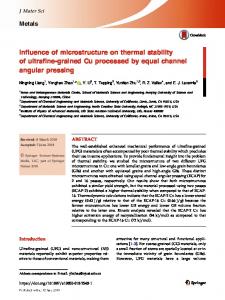
2.1. Introduction The Longmenshan Fault Zone (LFZ; Fig. 2.1), which runs some 400 km northeastwards through the Wenchuan, Beichuan and Qingchuan counties of Sichuan province, southwestern China, slipped catastrophically during the Great Wenchuan Earthquake (Mw 7.9) of May 12th 2008. Immediately after this event, multiple field surveys were initiated by the Chinese government to investigate the newly developed surface ruptures and associated exposures of the LFZ (Liu-Zeng et al., 2009; Xu et al., 2009). At the same time, a comprehensive research program was initiated, including work on the physical and mechanical properties of the main rock types of the region, with the aim of understanding in detail the rupture phenomena associated with the Wenchuan earthquake.
Figure 2.1. The central part of the Longmenshan Fault Zone (LFZ) in Sichuan, southwestern China, roughly 60 km to the northwest of Chengdu. The surface rupture induced by the Wenchuan Earthquake is indicated by the bold portions of the various fault traces (Liu – Zeng et al. (2009); Xu et al. (2009)). The main map was compiled after Xu et al. (2008). YBF = Yingxiu – Beichuan Fault; WMF = Wenchuan – Maoxian Fault; PF = Pengguan Fault; PQF = Pingwu – Qingchuan Fault.
During the course of several field campaigns, samples were collected from the main rock formations cut by the faults making up the LFZ, and from trenched, surface 41
Chapter II
ruptures. The samples were brought to the China Earthquake Administration (CEA) laboratory in Beijing for detailed investigation of their rock mechanical properties. In this Chapter, we report and discuss the results of rock friction experiments performed on samples prepared from representative sedimentary rocks and from a trenched fault gouge from the Yingxiu – Beichuan portion (YBF) of the LFZ (Fig. 2.1). According to ongoing field and seismological research, the central section of the YBF is one of the most heavily ruptured parts of the LFZ. Slip on this section initiated at a depth of 13-16 km (Huang et al., 2008; U.S. Geological Survey Earthquake Hazards Program, 2008; Pei et al., 2010; Wang et al., 2009). Rock friction studies provide constraints on the frictional strength of fault zone rocks during pre-, co- and post-seismic slip. All of these aspects need to be understood in detail if we are to build numerical models that link stress-field evolution and fault response, with the aim of gaining better insight into the likely location, frequency and magnitude of future seismogenic events (Tullis, 1988; Sykes et al., 1999; Rebetskii, 2002; Scholz, 2002). In particular, near-surface dynamic rupture propagation, triggered by ruptures propagating from depth, can only be constrained if we understand the frictional properties of the lithologies that dominate the shallow subsurface (Boatwright and Cocco, 1996; Tinti et al., 2005; Mizoguchi et al., 2008). For the LFZ, this means that we need to investigate representative sedimentary rocks collected in the field, as well as fresh, natural fault gouge collected from active faults, i.e. surface ruptures. Using this strategy, we attempt to answer the following questions: i. What is the effect of seismic rupture and gouge formation on the frictional strength of typical sedimentary rocks from the LFZ region? In other words, how weak are natural fault gouges from the LFZ with respect to their protoliths?F ii. How weak are the shallow sedimentary rocks of the LFZ, in terms of frictional strength, compared with the crystalline quartzofeldspathic and/ or mafic rocks expected at hypocentral depths? iii. What is the role of these shallow sediments during seismic slip, compared with underlying basement rock? Do they offer stable resistance to coseismic rupture propagating from below without producing abrupt stress drops, or do they show unstable slip plus a major internal stress drop? Answering question (i) should help predict the loci of surface ruptures associated with 42
Frictional properties of sedimentary rocks from the LFZ, Sichuan, China
future earthquakes. Answering questions (ii) and (iii) may help predict future damage risk from a knowledge of the relationship between basement and overlying sediments. Combining our results with the principles of rate and state dependent friction analysis, we discuss the implications of our findings for the seismotectonic setting of the LFZ and the earthquake process. 2.2. Background Before proceeding to describe our experiments, we first present essential background information on the regional geology of the LFZ and on the sampling strategy used. In addition, an introduction is given to the rate and state dependent friction law used as a theoretical framework to interpret our experimental results. 2.2.1. Regional geology and sampling strategy The Longmenshan fault zone is an imbricated, oblique thrust-fault system that accommodates eastward crustal extrusion of the Tibetan Plateau over the rigid lithosphere of the Yangtze block (Zhang et al., 2004; Densmore et al., 2007; Xu et al., 2008; Hubbard and Shaw, 2009). Located at the eastern edge of the Longmen Mountains, it marks the interface between the Songpan – Ganzi terrane (a Triassic orogenic belt) to the west and the Paleozoic – Cenozoic sediments of the Sichuan Basin to the east (Fig. 2.1). The fault system itself cuts through NNE-SSW trending, Neoproterozoic basement metamorphics marked by steeply westward dipping detachments (e.g. the Pengguan Complex). Overlapping these, Paleozoic to Triassic sediments of the Sichuan Basin are also found in the fault zone. (Tang et al., 2008; Xu et al., 2008). The sediments in particular are cut by numerous imbricate thrust faults that form a wedge of northeast-trending oblique thrusts dipping steeply to the northwest. These include the presently active Wenchuan – Maoxian Fault (WMF), the Yingxiu – Beichuan Fault (YBF) and the Pengguan Fault (PF) (or Guanxian – Anxian fault). Field mapping and post-earthquake satellite imaging showed that the Wenchuan earthquake ruptured both the YBF and PF, along the middle-segment of the LFZ, producing rupture scarps up to 10 m in height (Liu-Zeng et al., 2009; Xu et al., 2009). In the present study, we focused on Upper Triassic sedimentary rocks from the Xujiahe Formation, found near the southernmost ruptured part of the YBF in the central LFZ region (Fig. 2.1 inset map). The Xujiahe Fm is widespread in the LFZ and Sichuan basin. It shows strong lateral variations in lithology, but in essence comprises rocks deposited in a fluvio-deltaic setting, including conglomerates, sandstones, siltstones, 43
Chapter II
lacustrine limestones and mudstones, with some coal interbeds and often high carbonaceous content (Tang et al., 2008; Zhu et al., 2009). To investigate the response of the Xujiahe Fm to seismic rupturing, various end-member lithologies found in the Xujiahe Fm were sampled. Our samples thus consisted of a grey lacustrine limestone (08-WC-34), a black carbonaceous sandstone (08-WC-39) and a black carbonaceous mudstone (08-WC-05), sampled at the locations shown in Fig. 2.1. In addition, a ruptured segment of the YBF cutting sandstone and mudstone of the Xujiahe Fm, was trenched at Bajiaomiao, near Hongkou, to study the structure of the fault and to sample the black fault gouge (WF-09-06-10; Fig. 2.1). From surface ruptures along the fault trace it was inferred that the fault slipped at least 2 m at this location during the Wenchuan earthquake of May 2008. Gouge samples measuring roughly 10 cm x 10 cm x 2.5 cm (~250 mL in volume) were extracted from a prominent planar band exposed in the trench. 2.2.2. Rate and State dependent Friction laws To date, laboratory rock friction studies have focused mainly on the resistance to and stability of sliding exhibited by bare rock surfaces and simulated, gouge-filled faults. The resistance to sliding, or frictional strength, is generally expressed in terms of the coefficient of friction µ, i.e. the ratio between the shear stress τ and the effective normal stress σeff acting on the fault plane. The effective normal stress is defined as the stress acting at right angles to the sliding surface (the normal stress σn) minus the pore fluid pressure (Pf) acting on the pore walls within the fault rock. The stability of frictional sliding of rock is thought to be related to the stability of natural fault zones (e.g. Lapusta and Rice, 2003; Paterson and Wong, 2005). An important unstable slip phenomenon that is commonly encountered in rock friction experiments is regular stick-slip behaviour, also thought to be closely related to the periodic nature of earthquakes (Brace and Byerlee, 1966). Insight into stick-slip behaviour was first obtained in slide-hold-slide and velocity stepping experiments performed both on sliding rock surfaces and simulated fault gouges (e.g. Dieterich, 1972, 1979, 1981; Scholz and Engelder, 1976). These experiments led to the formulation of the phenomenological rate and state dependent friction law, or RSF law, which has proved to reproduce laboratory-derived rock friction data well and to describe key features such as regular stick-slip and the transition from stable sliding to unstable slip (e.g. Dieterich, 1979; Ruina, 1983; Rice and Ruina, 1983; Gu et al., 1984). 44
Frictional properties of sedimentary rocks from the LFZ, Sichuan, China
In RSF constitutive relations, the coefficient of friction is expressed as a function of slip velocity V and a state variable θ, as follows:
* a ln(V / V* ) b ln ( / * )
(2.1a)
or
* a ln(V / V* ) b ln (V* / Dc )
(2.1b)
where 𝜇∗ is the coefficient of friction for steady-state slip at a reference velocity 𝑉∗ characterized by an internal reference state θ* (e.g. Linker and Dieterich, 1992; Marone, 1998a). Note that the state variable θ has dimensions of time and can be interpreted as the average age of the population of contacts between two sliding surfaces, or their average life-time when the fault surfaces or gouge are in motion. The parameters a and b are empirical constants that describe the magnitudes of the direct and evolution effects, respectively. The direct effect is the instantaneous jump in friction coefficient that is observed upon perturbation of the sliding velocity at steady-state, i.e. from sliding at velocity V*, while the evolution effect describes transient adjustments that occur over a characteristic slip distance Dc required to re-attain steady-state friction at the new sliding velocity V (Marone, 1998a). In practice, two classes of evolution laws have been put forward to describe the transient evolution of θ, namely the slip and slowness laws. These differ in physical interpretation and mathematical definition of the parameters appearing in (2.1). In the case of the slowness law, the evolution of the state variable under constant effective normal stress is described by the differential equation (Dieterich, 1979; 1981)
d / dt 1 V / Dc
(2.2a)
Here, the state variable θ evolves with time, even when the frictional surface is under truly stationary contact (V = 0). For the slip law, again at constant effective normal stress, the evolution of the state variable is described by the relation (Ruina, 1983; Linker and Dieterich, 1992)
d / dt (V / Dc ) ln V / Dc
(2.2b)
45
Chapter II
In this case, it is evident that the state variable changes only during active slip and does not change (dθ/dt = 0) during stationary contact (V = 0). These evolution laws can simulate different aspects of the mechanical data obtained from frictional sliding experiments (Perrin et al., 1995; Marone, 1998a; He et al., 2003; Ampuero and Rubin, 2008), but microphysical models that can fully describe frictional sliding phenomena are yet to be agreed upon (for a discussion see Paterson and Wong, 2005). The slowness law is more commonly used because of observations of timedependent healing phenomena between sliding surfaces (e.g. Dieterich and Kilgore, 1994; 1996). Nonetheless, from (2.1b) and (2.2) it follows that the coefficient of friction at steady-state, µss, for both evolution laws reduces to
ss * (a b) ln(V / V* )
(2.3)
For both forms of RSF evolution law, the sign and magnitude of the difference between the rate dependence constants (a-b), is a measure of so-called velocity strengthening versus velocity weakening behaviour. This is crucial to the stability of frictional systems (Ruina, 1983), and is determined by interaction between frictional sliding of the sliding surfaces (or shearing of gouge) and their elastic surroundings. A velocity strengthening system exhibits a positive dependence of steady-state frictional strength on displacement rate. In such systems, slip instabilities are quickly damped to a state of stable sliding. By contrast, velocity weakening systems show a negative rate dependence, and slip rate perturbations can lead to a state of regular stick-slip provided that the stiffness of the system falls below a given critical value (Ruina, 1983). Whether a fault displays velocity strengthening or velocity weakening is recognized to be of key importance in determining whether earthquake nucleation is possible and what the response will be to dynamic rupture propagation (Tse and Rice, 1986; Rudnicki, 1988; Dieterich, 1992; Boatwright and Cocco, 1996; Tinti et al., 2005; Ampuero and Rubin, 2008). The value of (a-b) is therefore key. It can be quantified using a differential expression implicit in (2.3), i.e. using the relation
(a b) ss / ln(V )
46
(2.4)
Frictional properties of sedimentary rocks from the LFZ, Sichuan, China
Previous studies have investigated how (a-b) depends upon temperature, normal stress, chemical environment and the intrinsic properties of the sliding surfaces, such as roughness, gouge mineral constituents and gouge particle size (e.g. Dieterich, 1981; Lockner et al., 1986; Biegel et al., 1989; Linker and Dieterich, 1992; Kilgore et al., 1993; Saffer and Marone, 2003; Blanpied et al., 1995; He et al., 2006, 2007). The absolute values of a, b and of other constants in the RSF law as expressed in equations 2.1 and 2.2 cannot be directly extracted from experimental data individually, because of the mechanical interaction between the sample and the loading system. To do so, forward and inverse modeling techniques are required (e.g. Tullis and Weeks, 1986; Reinen and Weeks, 1993). Fortunately, however, the rate dependence (a-b) can be estimated using a finite difference form of equation 2.4, i.e. from measurements of the steady-state coefficient of friction at high and low velocities. 2.3. Experiments 2.3.1. Approach and choice of conditions In the present study, we make use of the RSF formulation and analysis described above to investigate the frictional properties of the sedimentary lithologies and fault rocks sampled from the Xujiahe Fm (Fig. 2.1). The experiments aim to address the frictional behaviour of these materials under shallow, upper crustal pressure and temperature conditions. The present friction tests consist of so-called ‘saw-cut’ sliding experiments performed in a servo-controlled, triaxial testing machine at the Institute of Geology of the CEA in Beijing. In this type of experiment, samples prepared from crushed rock or natural gouge are sheared between obliquely cut, cylindrical driver blocks under a given confining pressure. The shear and normal stresses acting on the slipping surface are measured, and, after applying appropriate corrections to the data, the frictional behaviour of the sample can be analyzed. Note that the triaxial machine used allows the normal stress acting on the simulated fault plane to be held constant during an individual experiment, through servo-control of the confining pressure. We ran the experiments at a nominal confining pressure and pore pressure corresponding to in-situ values of the lithostatic pressure and pore pressure at a depth of ~2 km in the LFZ. The lithostatic pressure was estimated to be roughly 50 MPa, taking an overburden density of ρ ≈ 2450 kg m-3 (Jiang and Jin, 2005). Assuming high connectivity of fractures in the fault zone, the pore fluid pressure was taken to be hydrostatic, i.e. 20 MPa. To simulate various crustal depths in our 47
Chapter II
experiments and to assess the effect of temperature on friction, we varied the temperature from 25 to 150°C. Based on a heat flow of 55.3 mW/m 2 for the Longmenshan region (Wang, 1996), we estimated a one-dimensional geothermal gradient of ~18.5°C/ km. Temperatures of 100-150°C thus correspond to depths up to ~5 – 8 km, while 50°C corresponds to the in-situ temperature expected at 2 km depth alongside the applied confining pressure of ~50 MPa and the pore pressure of 20 MPa. 2.3.2. Sample material The experiments were performed on crushed granular samples prepared from intact limestone, sandstone and mudstone, and on an untreated natural fault gouge. Thin section analysis of the intact sedimentary rocks revealed that the carbonaceous mudstone and sandstone consisted mainly of quartz, feldspar and plant fragments embedded in a clayey, carbon-rich matrix. The mudstone consisted of ~65-70% of very fine grained ( 4.5 mm, τ decreases strongly with increasing v (i.e. marked velocity-weakening occurs), and stick-slip events are widespread (Figs. 5.7a-d).
189
Chapter V
Figure 5.7. a). Plot of shear stress (τ) against displacement for experiment CaCO3-500-LV (performed at 500°C , 𝜎𝑒𝑓𝑓 𝑛 = 50 MPa, see Table 5.1), with the displacement rate data (velocity steps) added on the right axis. b) Displacement interval x = [4.1, 6.6] mm showing downward steps in sliding velocity from 1 to 0.3 to 0.03 µm/s. c) Displacement interval x = [15.2, 21.0] mm showing downward steps in sliding velocity from 3 to 1 to 0.3 to 0.1 to 0.03 to 0.05 µm/s. d) Highlight of c), showing stick-slips at v = 0.03 µm/s, transitioning to stable sliding at x = 17.4 mm.
190
Frictional-viscous transition in simulated calcite fault gouge sheared at 20-600°C
5.4.1.4. Amplitude of stick-slip events As described above, stick-slip behaviour became increasingly marked at temperatures in the range 100° to 550°C, especially at the lower sliding velocities. This is reflected in the amplitude of stick-slip, i.e. in the magnitude of the associated stress drops ∆τdrop. The largest stress drops seen in our tests were measured in experiment CaCO 3-500-LV (Fig. 5.7), which showed ∆τdrop ≈ 25 MPa. For each experiment that showed stick-slip, we plotted the magnitude of the average stress drop ∆τdrop against temperature and sliding rate in log-linear and log-log space respectively (Figs. 5.8a, b). These plots demonstrate that ∆τdrop increases strongly with increasing temperature in the range 100° to 550°C (Fig. 5.8a), whereas it falls to zero at 600°C where stick-slip ceases. In addition, ∆τdrop clearly decreases with increasing sliding velocity (Fig. 5.8b), especially at v > 1 μm/s.
𝑒𝑓𝑓
Figure 5.8. Plot of the stress drop (on a log-scale), for those experiments performed at constant 𝜎𝑛 = 50 MPa which showed stick-slip, against (a) temperature (on a linear scale) and (b) sliding velocity (on a log-scale).
191
Chapter V
5.4.2. Effective normal stress stepping experiments 𝑒𝑓𝑓
The shear stress vs. displacement curves obtained for all 𝜎𝑛 -stepping experiments 𝑒𝑓𝑓
are presented in Figure 5.9. In each interval of constant 𝜎𝑛 , the shear strength (τ) values (τI, τII, and τIII) and apparent friction coefficient (μ) show a similar evolution with displacement, and with temperature and sliding velocity, as seen in the experiments 𝑒𝑓𝑓
performed at constant 𝜎𝑛 𝑒𝑓𝑓
𝜎𝑛
(Fig. 5.9 cf. Fig. 5.5, see also Table 5.2). As in the constant
𝑒𝑓𝑓
tests, in the 𝜎𝑛 -stepping tests we frequently observed stick-slip in experiments
performed at mid-range temperatures, specifically at 200° to 500°C in this case. Plots of τI, τII, and τIII against effective normal stress are shown in Figure 5.10a, and of τss or else τfail measured at each sliding velocity used in the second cycle of velocity steps applied in 𝑒𝑓𝑓
each interval of constant 𝜎𝑛 , in Figure 5.10b. Note that for the latter, this resulted in two values of τ for each v = 1 and 10 μm/s, and 1 value for v = 100 μm/s (cf. Fig. 5.4b, 𝑒𝑓𝑓
covering Stage II & III of each 𝜎𝑛
interval). Within the range of normal stresses 𝑒𝑓𝑓
investigated, and for each temperature and sliding velocity studied, all τ vs. 𝜎𝑛 data are 𝑒𝑓𝑓
well described using a straight line. Linear regression analysis, using 𝜏𝑘 = 𝑆0 + 𝜇0 𝜎𝑛 , yielded the S0 and μ0 given in Table 5.3. The values of μ0 show a similar trend with temperature as μ-values determined from all other experiments (Table 5.3 cf. Table 5.2). Taking into account the standard error, we found no systematic dependence of S0 on temperature or sliding rate.
192
Frictional-viscous transition in simulated calcite fault gouge sheared at 20-600°C
Figure 5.9. Plots of shear stress (τ) against displacement for the 𝜎𝑒𝑓𝑓 𝑛 -stepping experiments. a) T ≈ 20° and 200°C. b) T ≈ 400°, 500°, and 550°C. c) T ≈ 600°C. Steps in 𝜎𝑒𝑓𝑓 as indicated. A list of all 𝑛 experiments is given in Table 5.1, and a list of τI , τII , and τIII values is given in Table 5.2.
193
Figure 5.10. Plots of shear stress (τ) against effective normal stress (𝜎𝑒𝑓𝑓 𝑛 ) for the temperatures indicated in the sample codes and the sliding velocities shown. a) Values of τI, τII, and τIII (for a list of values see Table 5.2). b) Values of τss (or else τfail) measured, at each sliding velocity, in the second cycle of velocity steps, applied within each 𝜎𝑒𝑓𝑓 𝑛 step (cf. Figs. 5.4b, 5.9). For a list of linear regression parameters, see Table 5.3.
τk = S0 + μ0 · σneff
Experi- Tmn ment (°C)
τI S0
τII
τIII
v = 1 μm/s
μ0
R2
S0
μ0
R2
S0
μ0
R2
S0
v = 10 μm/s
μ0
R2
S0
μ0
R2
v = 100 μm/s S0
μ0
R2
CaCO3NS-20
17.9 ±0.4
3.73 ±1.25
0.64± 0.02
0.998
2.64 ±2.05
0.67± 0.03
0.994
3.90± 2.92
0.63± 0.04
0.987
2.29 ±1.58
0.72± 0.02
0.993
3.89 ±1.62
0.64± 0.02
0.991
1.55 ±2.41
0.75± 0.03
0.994
CaCO3NS-200
199 ±1.0
5.30 ±1.87
0.47± 0.03
0.990
0.36 ±1.37
0.54± 0.02
0.996
0.22± 1.09
0.54 ±0.01
0.998
1.49 ±1.10
0.52± 0.02
0.994
0.19 ±0.73
0.54 ±0.01
0.997
1.27 ±2.11
0.55± 0.03
0.991
CaCO3NS-400
398 ±4.8
11.6 ±3.72
0.42 ±0.05
0.954
4.75 ±3.30
0.45 ±0.05
0.968
2.68± 2.60
0.47± 0.04
0.982
3.24 ±1.48
0.43± 0.02
0.983
4.16 ±1.80
0.47± 0.03
0.980
5.02 ±3.40
0.38 ±0.05
0.952
CaCO3NS-500
500 ±9.9
8.09 ±1.04
0.58 ±0.01
0.998
-1.67 ±1.34
0.62± 0.02
0.997
-1.13 ±0.45
0.62 ±0.01
1.000
-1.32 ±1.63
0.53± 0.02
0.984
-1.25 ±0.66
0.62± 0.02
0.998
6.53 ±2.67
0.32± 0.04
0.959
CaCO3NS-600
614 ±5.6
11.0 ±2.04
0.53± 0.03
0.991
1.52 ±0.65
0.58 ±0.01
0.999
0.68± 1.18
0.58± 0.02
0.998
-2.89 ±1.08
0.62± 0.02
0.995
1.02± 0.60
0.58 ±0.01
0.999
-3.81 ±1.17
0.60± 0.02
0.998
Table 5.3. List of regression parameters obtained from fits on shear stress – effective normal stress curves (see Fig. 5.10).
Chapter V
5.4.3. Velocity dependence of strength (Γ) We determined the velocity dependence of strength (Γ) using equation 5.2, for all velocity steps performed in Stage II of all experiments (with the exception of CaCO 3-500LV). We determined Γ values from Stage II only because i) strong displacementweakening associated with low displacements in experiments performed at 100° ≤ T ≤ 600°C has come to an end (see e.g. Fig. 5.5), and ii) Stage II provides a full cycle of downward and upward velocity steps from 100 to 0.1 or else 1 μm/s (see Figs. 4a, b). A list of Γ values is given in Table 5.4. These data were used to plot Γ against temperature, post-step sliding velocity (v2), and effective normal stress (see Figs. 5.11a-c). The results show a transition from velocity strengthening (Γ ≈ 0.00 to 0.02) at 18°C to velocity weakening (Γ ≈ -0.01) at 100°C (Fig. 5.11a, Table 5.4). At 200°C (experiment CaCO3-200), upward steps in sliding velocity produced velocity strengthening (Γ > 0) at v2 ≥ 30 µm/s versus velocity weakening (Γ < 0) at v2 < 30 µm/s. Similarly, downward steps in sliding velocity yielded velocity strengthening (Γ > 0) at v ≥ 3 µm/s versus velocity weakening (Γ < 0) at v < 3 µm/s (Fig. 5.11b, Table 5.4). In the experiments performed at T = 400-550°C, all steps were characterized by velocity weakening behaviour, with Γ decreasing to a sharp minimum at T ≈ 500-550°C (Figs. 5.11a, b and Table 5.4). Note that this temperature range of 400° to 550°C is that where stick-slip behaviour was most marked, particularly at the lower sliding velocities used (Figs. 5.5, 5.8, 5.9). At 600°C (experiment CaCO3-600), near-velocity-neutral behaviour dominated. In detail, minor velocity strengthening occurred in upward steps with v2 = 0.3 µm/s, versus minor velocity weakening at v2 ≥ 3 µm/s. In downward steps, we found velocity strengthening for v2 = 3 and v2 = 10 µm/s, versus velocity weakening for v2 = 30 µm/s. By comparison with the effect of temperature, Γ was found to be more or less independent of velocity (i.e. v2) and of σneff, except at 500°C where Γ decreased with increasing σneff (Fig. 5.11c, Table 5.4).
196
Frictional-viscous transition in simulated calcite fault gouge sheared at 20-600°C
Figure 5.11. Plots of the velocity dependence of strength Γ, determined from Stage II of all experiments (with the exception of CaCO3-500-LV), against a) temperature (T), b) post-step sliding velocity (v2), and c) effective normal stress (𝜎𝑒𝑓𝑓 𝑛 ). Γ values were obtained using eq. 5.2, and are listed in Table 5.4. Data from experiment CaCO3-500-LV were excluded because this test employed a unique displacement-velocity history (see Table 5.1).
197
Experiment1)
Tmn (°C)
σneff (MPa)
CaCO3-RT CaCO3-100 CaCO3-200 CaCO3-400 CaCO3-500 CaCO3-550 CaCO3-600
22.2±0.7 98.8±1.1 199±0.9 399±0.9 494±2.3 537±2.3 592±1.9
50 50 50 50 50 50 50
100→10
10→1
1→10
10→100
CaCO3-NS-RT
17.9±0.4
CaCO3-NS-200
199±1.0
30 50 80 100 30 50
0.002 0.002 0.007 0.008 n/a3) 0.009
0.003 0.013 0.019 0.018 n/a3) 0.002
0.011 0.018 0.022 0.022 n/a3) 0.004
0.006 0.012 0.011 0.015 n/a3) 0.011
80 100 30 50 80 100
0.010 0.008 -0.003 -0.023 -0.010 -0.013
-0.002 -0.007 -0.017 -0.008 -0.022 -0.021
0.005 -0.003 -0.032 -0.016 -0.029 -0.014
0.009 0.010 -0.001 -0.003 -0.008 -0.013
30 50 80 100 30 50 80 100
-0.003 -0.009 -0.030 -0.043 -0.008 -0.013 -0.009 -0.003
-0.020 -0.039 -0.058 -0.050 -0.013 -0.029 -0.019 -0.018
-0.026 -0.037 -0.050 -0.041 -0.038 -0.031 -0.011 0.012
-0.001 -0.011 -0.042 -0.056 -0.024 -0.022 -0.017 -0.009
CaCO3-NS-400
398±4.8
CaCO3-NS-500
500±9.9
CaCO3-NS-600
614±5.6
v-down steps2)
v-up steps2)
100→30
30→10
10→3
3→1
1→0.3
0.3→0.1
0.1→0.3
0.3→1
1→3
3→10
10→30
30→100
-0.001 0.000 0.005 -0.003 -0.004 -0.047 -0.008
0.002 -0.005 0.003 -0.003 -0.021 -0.061 0.005
0.003 -0.004 0.010 -0.014 -0.043 -0.065 0.005
0.006 -0.005 -0.010 -0.020 -0.044 -0.043 n/a3)
0.015 -0.004 -0.014 -0.017 -0.041 -0.096 n/a3)
0.007 -0.005 -0.024 -0.024 -0.037 -0.049 n/a3)
0.005 -0.003 -0.015 -0.013 -0.013 -0.009 0.024
0.009 -0.002 -0.006 -0.011 -0.028 -0.023 n/a3)
0.009 -0.002 -0.002 -0.015 -0.017 -0.023 -0.003
0.011 -0.001 -0.002 -0.017 -0.018 -0.018 -0.002
0.010 -0.001 0.009 -0.006 -0.014 -0.024 0.000
0.002 -0.004 0.008 -0.002 -0.120 -0.020 -0.014
Table 5.4. List of rate sensitivity parameter values (Γ = ∆τ/ (σneff ∙ ∆lnv). 1)Data from experiment CaCO3-500-LV were excluded because this test employed a unique displacement-velocity history (see Table 5.1). 2)Velocity steps applied in Stage II (see Fig. 5.4). Grey shading indicates that the data showed stick-slip after the step. Sliding velocity in μm/s. 3)Sliding did not reach a constant (average) τss or τfail, preventing determination of Γ.
Frictional-viscous transition in simulated calcite fault gouge sheared at 20-600°C
5.5. Microstructural observations Investigation of the sheared gouge microstructures showed major differences between samples sheared at relatively low (20° to 200°C) versus relatively high (400° to 600°C) temperatures, whereas only minor differences were found between samples recovered from the constant effective normal stress versus the effective normal stress stepping experiments. Therefore, in the following we focus on samples from experiments conducted at different temperatures. 5.5.1. Microstructures developed at 20° to 200°C Upon separation of the internal ring shear pistons and removal of the outer confining ring, all samples recovered from experiments performed at 20° to 200°C split along a shear-induced fabric developed parallel and/ or inclined to the sample-piston interface. The samples frequently fell apart into numerous small fragments which we were unable to recover. Fortunately, from the gouge layer of experiment CaCO 3-NS-20, a relatively continuous and cohesive arc-shaped fragment could be retained and used for sectioning. Optical analysis showed that the gouge layer from experiment CaCO 3-NS-20 developed horizontal boundary and inclined shear bands (Y- and R1 shears, respectively, using the terminology of Logan et al., 1979) characterized by a strongly reduced grain size (