Hindawi Publishing Corporation International Journal of Aerospace Engineering Volume 2015, Article ID 723487, 8 pages http://dx.doi.org/10.1155/2015/723487
Research Article Stress Distribution on Sandwich Structure with Triangular Grid Cores Suffered from Bending Load Cui Xu, Huang Yanjiao, Wang Shou, Lu Chun, and Fang Luping Liaoning Key Laboratory of General Aviation and Liaoning Key Laboratory of Composite Manufacture technology, Shenyang Aerospace University, Shenyang 110136, China Correspondence should be addressed to Huang Yanjiao;
[email protected] Received 22 February 2015; Revised 13 May 2015; Accepted 18 May 2015 Academic Editor: Ronald M. Barrett Copyright © 2015 Cui Xu et al. This is an open access article distributed under the Creative Commons Attribution License, which permits unrestricted use, distribution, and reproduction in any medium, provided the original work is properly cited. Triangular grid reinforced by carbon fiber/epoxy (CF/EP) was designed and manufactured. The sandwich structure was prepared by gluing the core and composite skins. The mechanical properties of the sandwich structure were investigated by the finite element analysis (FEA) and three-point bending methods. The calculated bending stiffness and core shear stress were compared to the characteristics of a honeycomb sandwich structure. The results indicated that the triangular core ultimately failed under a bending load of 11000 N; the principal stress concentration was located at the loading region; and the cracks occurred on the interface top skin and triangular core. In addition, the ultimate stress bearing of the sandwich structure was 8828 N. The experimental results showed that the carbon fiber reinforced triangular grid was much stiffer and stronger than the honeycomb structure.
1. Introduction Fiber sandwich grid construction has been increasingly used in applications requiring high stiffness/high strengthto-weight ratio materials [1]. Sandwich structures generally consist of different cores in the middle which keep the two skins (top skin and bottom skins) apart from each other to provide a sandwich construction with high flexural stiffness and strength in a relatively lightweight structure [2]. In a sandwich structure, skins commonly carry most of the bending loads, whereas the core mainly bears the transverse shear and normal loads. Moreover, sandwich structures may fail by different modes such as face yielding, face wrinkling, core yield, indentation, and delamination depending on their geometries and material properties [3– 5]. Therefore, the selection of materials and the geometry of sandwich cores result in different failure mechanisms. The geometrical shape optimization for a grid structure has been recently analyzed in literature. The cores of the sandwich structures are conventionally made of foams or honeycombs, and some studies have shown the higher weight efficiency of grids structures than that of foams [6–9]. Xiong et al. [10] introduced pyramidal truss cores, and the fracture of the struts is the weakness of the bended structure. Hou
and Gramoll [11] have developed the automated filament winding process to fabricate Kagome and triangular conicalcomposite-lattice structures, and the strength-to-weight ratio in the triangular grids was twice as high as that in the Kagome grids. Han and Tsai introduced interlocked grid structures [12] with glass fiber ribs. Grids could have ribs running in several directions for multidirectional loading. Fan et al. aimed at extending an equivalent continuum method to analyze the three-dimensional lattice structures focusing on their effective stiffness, strength, and plastic yield surface. They concluded that the stretching dominated lattice materials were still much stiffer and stronger than the bending dominated cellular materials [13, 14]. Several studies on the honeycomb structure have shown that both the stiffness and strength are governed by the adjacent cell wall bending for all loading [15, 16]. In these structures, some cell faces are so thin in the honeycomb structure that their contribution to stiffness and strength is small [17]. Two types of cell joints and shuts differentiated by the transverse shut in a triangular grid core are shown in Figure 1. Honeycomb can be treated as a connected set of pin-jointed struts, and consider the pin-jointed frames shown in Figure 1(a). The struts about joints and the frame collapse at a high loading capacity. Moreover, these characteristics in the honeycomb
2
International Journal of Aerospace Engineering
Joint
3
2
3
4 5
2 6
1
1
Strut
(a)
(b)
Figure 1: Cell joints and shuts. (a) A cell joint frame in honeycomb structure. (b) Triangulated frame in a grid structure.
Wall thickness
3 mm
25.98 mm
(a)
25.98 mm
(b)
(c)
Figure 2: (a) Triangular lattice core. (b) One cell of honeycomb size. (c) One cell of triangular core size.
structure are deteriorated by the adjacent hexagonal structure (honeycomb structure), with only three shuts crossing over at a joint instead of six (in triangular grid structure). The triangulated frame shown in Figure 1(b) is a new structure. A comparison of the triangular core with the honeycomb sandwich structure is worth exploring. In the previous studies, honeycomb sandwich structure was studied according to the compression molding and gluing methods [18]. The results indicated that composite honeycomb sandwich possessed the excellent dynamic performance. The honeycomb sandwich structure is a low weight material for given structural requirement but suffers from several limitations. In this study, a carbon fiber reinforced triangular grid core is designed and manufactured to compare the mechanical properties with CF/EP honeycomb composite sandwich structure. A 3D FEA model was developed to perform the sandwich failure region, and the mechanical behaviors of the sandwich structure are tested by the threepoint bending method. Finally, the failure mechanism and mechanical properties of the new structure core are also discussed.
2. Experimental Techniques 2.1. Materials. In this structure, COCA401 silicon rubber was used by mould. Honeycomb and triangular core were prepared from T700 carbon fibers and epoxy resin as the materials, and the composite mechanical properties of T700/epoxy resin are listed in Table 1. CF/epoxy wave beam in the honeycomb sandwich structure was prepared by the compressing molding technique (wave length of the beam is 30 mm). The triangular core shown in Figure 2(a) was
Table 1: T700/epoxy resin composite mechanical properties [19]. Symbol
Value
𝐸11 𝐸22 𝐸33 𝑉12 , 𝑉13 𝑉23 𝐺12 , 𝐺13 𝐺23 𝑋𝑡
123 GPa 8.4 GPa 8.4 GPa 0.32 0.30 4 GPa 3 GPa 2100 MPa
𝑋𝑐
800 MPa
𝑌𝑡 𝑌𝑐 𝑆12 , 𝑆23 , 𝑆13
25 MPa 120 MPa 40 MPa
Concrete meaning Longitudinal elasticity modulus Transverse elasticity modulus Transverse elasticity modulus Poisson’s ratio Poisson’s ratio Epoxy resin shear modulus In-plane shear modulus Longitudinal tensile strength Longitudinal compressive strength Transverse tensile strength Transverse compressive strength In-plane shear strength
manufactured by the hand-molding and by vacuum-bag molding methods. The first layer of CF/epoxy is 0∘ ; the second layer is 60∘ ; the third layer is −60∘ ; and the fourth layer is 0∘ . The triangular core consisted of up to 100 layers (the core thickness is 15 mm). The sandwich skins were fabricated by the compressing molding technique with a thickness of 1 mm. Sandwich structure was prepared by gluing the core and skins together, and the total thickness of the sandwich structure was 17 mm. The assembly was placed in a vacuum bag thus completing the manufacturing process with a curing process of 80∘ C/2 h + 120∘ C/1 h + 150∘ C/1 h. The properties of skins and cores are listed in Table 2.
International Journal of Aerospace Engineering
3
Table 2: Layer property of the sandwich structure. Component
Layer angle (deg)
Layer thickness (mm)
Length (mm)
Width (mm)
Materials
Wall thickness (mm)
Skin Triangular core Honeycomb
[0/90]𝑛 [0/60/−60]𝑛 [0/90]𝑛
1 15 15
320 320 320
104 104 104
T700/epoxy resin T700/epoxy resin T700/epoxy resin
— 3 3
P
Top skin Glue Core
10 mm 1 80 mm a 1, 2-displacement sensor
160 mm l
80 mm a
Bottom skin
2
104 mm 320 mm
(a)
Load P
Figure 3: Three-point bending device.
2.2. Static Test in Three-Point Bending. The specimens were subjected to three-point bending using a universal testing machine (DDL50, Changchun Mechanical L.T.D) according to GB/T 1456-2005 protocol at a span length of 160 mm as shown in Figure 3. Load is applied at a constant speed of 2 mm/min. The specific core shear stress and sandwich flexural stiffness were calculated according to (1) and (2). The core shear stress was calculated using the following equation: 𝜏=
𝑃⋅𝐾 𝐾 = 1 − 𝑒−𝐴 2 ⋅ 𝑏 ⋅ (ℎ − 𝑡)
𝐴=
𝑙 6𝐺𝑐 (ℎ − 𝑡) [ ]. 4𝑡 𝐸𝑓 ⋅ 𝑡
(1)
𝜏 = core shear stress, MPa; 𝑃 = load, N; 𝑏 = sandwich width, mm; ℎ = sandwich thickness, mm; 𝑡 = facing thickness, mm; 𝐺𝑐 = core shear modulus, MPa; 𝐸𝑓 = facing elastic modulus, MPa. The sandwich flexural stiffness is as follows: 𝑙2 × 𝑎 × Δ𝑃 . 𝐷= 16𝑓1
(2)
𝐷 = sandwich flexural stiffness, N⋅mm2 ; 𝑎 = overhanging arm length in mm; Δ𝑃 = increasing load Δ𝑃 of loading-deflection curve initially, 𝑁; 𝑙 = span length, mm; and 𝑓1 = increasing deflection value corresponding to Δ𝑃 in mm.
Constraints
Constraints (b)
Figure 4: (a) Sandwich structure model. (b) FEM mesh model.
3 mm. The finite element model is shown in Figure 4(a). The core and two skins are glued together as a whole volume. The perfect bonding between the skins and grid core is assumed. The symmetric constraints are applied on the bottom of the supports and the increasing pressure 𝑃 is applied on the indenter. The 3D eight-node solid element SOLID 46 is adopted to mesh the CF/EP composites model as shown in Figure 4(b). 3.2. Failure Criteria Composite Materials. In this study, TsaiHill failure criteria [20, 21], as shown in (3), were used to characterize the damage region in the sandwich structure. Composites will fail if 𝜎1 , 𝜎2 , or 𝜏12 satisfies the following equation: (
𝜎1 2 𝜎 2 𝜎𝜎 𝜏 2 ) + ( 2 ) − 1 22 + ( 12 ) = 1. 𝑋𝑡 𝑌𝑡 𝑆 𝑋𝑡
(3)
𝜎1 and 𝜎2 are the on-axis stresses in the longitudinal and transverse directions; 𝜏12 is the on-axis in-plane shear stress; 𝑋𝑡 is the longitudinal tensile stress; 𝑌𝑡 is the transverse direction; and 𝑆 is the in-plane shear strength.
4. Results and Discussion 3. Finite Element Analysis 3.1. Finite Element Modeling. The following analysis is focused on the sandwich structure. The finite element analysis method was used to characterize the materials principal direction stresses distribution in the sandwich structure. The sandwich part is composed of a CF/EP composite core (length: 320 mm, width: 104 mm) and two skins with a thickness of 1 mm and the wall thickness in the core is also
4.1. Finite Element Analysis. The distribution of the principal direction stress on the full sandwich structure when suffered from 11000 N bending load is shown in Figure 5, indicating the failure elements and stress distribution. Some failures predict that the sandwich structure starts to enter into the matrix cracking deformation stage when the materials principal direction stresses in some elements reach the yielding strength under 11000 N. Figure 5(a) shows that
0.313E + 08
0.232E + 08
0.151E + 08
0.704E + 07
−0.104E + 07
0.103E + 08
−0.110E + 08
−0.324E + 08
−0.537E + 08
−0.750E + 08
−0.963E + 08
−0.118E + 09
−0.139E + 09
−0.160E + 09
(b)
−0.182E + 09
(a)
−0.912E + 07
−0.172E + 08
−0.253E + 08
−0.333E + 08
−0.414E + 08
0.102E + 09
0.885E + 08
0.747E + 08
0.608E + 08
0.470E + 08
0.331E + 08
0.192E + 08
0.539E + 07
−0.846E + 07
International Journal of Aerospace Engineering
−0.223E + 08
4
(c)
Figure 5: Full sandwich structure stress distribution: (a) 1st principal stress; (b) 2nd principal stress; (c) 3rd principal stress.
the 1st principal stress (the maximum principal stress) is 102 MPa, and some failures are obviously located at the loading region from the top skin in Figure 6. The 1st principal stress in the top skin is 60.2 MPa. The results also indicate that the stress concentration is located at the supporting region. The top skin is commonly known to suffer from the compression stress and, by comparison, the bottom skin bears tension stress during the bending load process. A tendency of failures occurring near the indenter indicates that the indenter makes the top skin more susceptible to stress concentrations developed in the top surface region. Figure 7 shows that the triangular core occurs on severe destruction under the indenter, demonstrating that the core reached yielding strength suffered from 11000 N load. Although there are no failed elements existing in the bottom skin, the principal stress appears in the region damaged in Figure 8. The number of core shear cracks appears to be followed by several damages on top skin. In conclusion, the failure mechanism at the top skin is face yielding; core shear failure dominates the failure mechanism in the triangular grid core. As the stress concentrations develop to some extent, the triangular grid sandwich structure will completely lose its load-bearing capacity and ultimately collapse. Therefore, the FEA indicates that the failures occur by localized collapse of
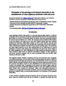
the interface between the triangular grid core and composite top skin directly beneath the indenter. 4.2. Sandwich Structure Mechanical Performance. Figure 9 shows the typical load-deflection curve obtained under static three-point bending on the sandwich structure. After the structure enters into the plastic deformation stage, the nonlinear damage initiation is made by debonding instability as shown in Figure 10(b). The weakness of the sandwich structure lies in the adhesion strength between the skins and core from Figure 10(b). Therefore, the weakness of the sandwich grid structure leads to a sudden drop of load in the bending curve from 8818 N to 6000 N as shown in Figure 9. The face wrinkling failure shown in Figure 10(b) indicates that debonding is a weakness of the carbon fiber reinforced sandwich structure. The top skin is also compressed during bending. As the displacement increases, the top skin tends to damage because of the failure adhesion to the grid core. Owing to the scatter in the adhesion strengths, two large different peaks of the load-deflection curve emerge. Although a top skin fails, the bottom skin and the core are also still adhered together; therefore the increasing loading is supported by the sandwich structure including the bottom skin and the core. As the displacement continues, the grid core bears larger force than before, thus resulting in a core
(a)
0.115E + 08
0.743E + 07
0.332E + 07
−788494
−0.490E + 07
−0.901E + 07
−0.131E + 08
−0.172E + 08
−0.213E + 08
−0.255E + 08
0.451E + 08
0.385E + 08
0.319E + 08
0.253E + 08
0.187E + 08
0.826E + 07
−0.128E + 08
−0.339E + 08
−0.550E + 08
−0.761E + 08
−0.972E + 08
−0.118E + 09
−0.139E + 09
−0.160E + 09
−0.182E + 09
(a)
0.369E + 07
−0.117E + 08
−0.271E + 08
−0.425E + 08
−0.579E + 08
−0.733E + 08
−0.887E + 08
−0.104E + 09
−0.119E + 09
−0.135E + 09
0.120E + 08
0.542E + 07
−0.119E + 07
−0.781E + 07
−0.144E + 08
0.195E + 08
0.127E + 08
0.596E + 07
−806985
−0.758E + 07
−0.143E + 08
−0.211E + 08
−0.279E + 08
−0.347E + 08
−0.414E + 08
0.603E + 08
0.511E + 08
0.420E + 08
0.328E + 08
0.236E + 08
0.144E + 08
0.523E + 07
−0.395E + 07
−0.131E + 08
−0.223E + 08
International Journal of Aerospace Engineering 5
(b)
(c)
Figure 6: Top skin stress distribution: (a) 1st principal stress; (b) 2nd principal stress; (c) 3rd principal stress.
(b)
(c)
Figure 7: Triangular core stress distribution: (a) 1st principal stress; (b) 2nd principal stress; (c) 3rd principal stress.
0.313E + 08
0.240E + 08
0.167E + 08
0.947E + 07
0.221E + 07
0.696E + 07
−0.121E + 08
−0.312E + 08
−0.502E + 08
−0.693E + 08
−0.883E + 08
−0.107E + 09
−0.126E + 09
−0.145E + 09
(b)
−0.165E + 09
(a)
−0.506E + 07
−0.123E + 08
−0.196E + 08
−0.269E + 08
−0.341E + 08
0.101E + 09
0.879E + 08
0.747E + 08
0.616E + 08
0.485E + 08
0.354E + 08
0.222E + 08
0.913E + 07
−0.400E + 07
International Journal of Aerospace Engineering
−0.171E + 08
6
(c)
Figure 8: Bottom skin stress distribution: (a) 1st principal stress; (b) 2nd principal stress; (c) 3rd principal stress.
10000 8818 N
8828 N
8000
Load (N)
Debonding 6000 4000
Core shear 6000 N
Elasticity
Subdued loading capacity
2000 0
2
4 6 Displacement (mm)
8
10
Figure 9: Load-deflection curve of triangular grid sandwich structure (specimen 1).
failure from Figure 10(c). Therefore, the core shear failure leads to another abrupt drop in the peak loading capacity of the sandwich structure. Finally, the ultimate collapse sandwich structure still offered subdued loading capacity of 5300 N or 60% of the peak loading. In conclusion, these
effects are clearly observed in the load-deflection curve and produce an abrupt load loss of 8828 N as the loading capacity. The predicted loading capacity (11000 N) in FEA (higher than the value reported for the experimental result of 8828 N) is at least 24.6% higher than the strength measured from the experiments. The perfect bonding between the skins and triangular core in the FEM model is known. In fact, there are fiber voids defect in some cores because of uneven epoxy resins distributions. Many fiber voids defect (in Figure 11) occur during the curing process in the manufacturing and may detrimentally weaken the mechanical properties of the sandwich structure. Triangular core (including three specimens) and honeycomb sandwich structure stress and strain curve, discussed previously, are shown in Figure 12. The maximum and minimum stresses of the triangular core are 39.07 and 34.63 N/mm2 , respectively, which are higher than those of the honeycomb sandwich structure (28.80 N/mm2 ) of the same size as listed in Table 3. From the measured data shown in Table 3, the bending stiffness and core shear stress of the triangular grid core are also still higher than those of the honeycomb with the same size. Triangular core 3 failed at 9766.97 N, and the weight of this specimen was 115.01 g. The strength-to-weight ratio was 84.92 N/g and was approximately twice as high as that of the honeycomb sandwich structure. Overall, the carbon fiber reinforced triangular grid
International Journal of Aerospace Engineering
7 40 35
(a)
𝜎 (N/mm2 )
30
(b)
25 20 15 10 5 0
2
0
4
6
8
10
x (mm) Triangular core 1 Triangular core 2
(c)
Figure 10: Bending behaviors of the triangular sandwich structure (specimen 1). (a) Elastic deformation. (b) Skin buckling and debonding. (c) Core shear.
Table 3: Comparison of mechanical properties in different sandwich structures.
Triangular grid core 1 Triangular grid core 2 Triangular grid core 3 Honeycomb
Figure 12: Stress-strain curve of sandwich structure.
(1) The maximum stress load 𝑃 compared to the results using 3D model and experiments shows that the average damage variables are within 24.6%. FEA shows that face yielding and core shear failure play a dominating role in the sandwich grid structure and the number of top skin breakage and damage core indicates the structure failure mechanism, which are in good agreement with the experiments.
Figure 11: Fiber voids defect.
Component
Triangular core 3 Honeycomb structure
𝐷 (N⋅mm2 )
𝜏 (MPa)
Ultimate load (N)
Weight (g)
𝑃/𝑊 (N/g)
3.78𝑒8
3.68
8828.23
110.33
80.02
3.86𝑒8
3.75
9766.97
115.01
84.92
3.71𝑒8
3.65
8658.78
105.87
81.79
3.56𝑒8
3.12
7498.56
169.05
44.36
(2) Experimental tests were performed to study the failure behavior of both the honeycomb and triangular grid sandwich structure to provide upper estimates for the load-carrying capacity of the structure. The comparison of various structures shows that the carbon fiber reinforced triangular grid structure is much stiffer and stronger than the traditional honeycomb structure.
Conflict of Interests The authors declare that there is no conflict of interests regarding the publication of this paper.
𝐷 = sandwich flexural stiffness, 𝜏 = core shear stress.
Acknowledgments
sandwich structure exhibited better mechanical performance than that of the honeycomb structure.
The authors gratefully acknowledge the support by the program for Liaoning Excellent Talents University (Grade no. LJQ2012013); the project is sponsored by Liaoning BaiQianWan Talents Program (no. 2014921048) and Science Foundation of China (Grant no. 51373102).
5. Conclusions A 3D finite element model of the triangular grid sandwich structure is established to simulate the failure of the sandwich structure by the Tsai-Hill failure criteria. According to threepoint bending tests and a finite element 3D model, the mechanical behavior of the sandwich structures is as follows:
References [1] Z. B. Li, Z. J. Zheng, J. L. Yu, C. Qian, and F. Lu, “Deformation and failure mechanisms of sandwich beams under three-point bending at elevated temperatures,” Composite Structures, vol. 111, no. 1, pp. 285–290, 2014.
8 [2] A. C. Manalo, “Behaviour of fibre composite sandwich structures under short and asymmetrical beam shear tests,” Composite Structures, vol. 99, pp. 339–349, 2013. [3] T. M. McCormack, R. Miller, O. Kesler, and L. J. Gibson, “Failure of sandwich beams with metallic foam cores,” International Journal of Solids and Structures, vol. 38, no. 28-29, pp. 4901– 4920, 2001. [4] J. Yu, E. Wang, J. Li, and Z. Zheng, “Static and low-velocity impact behavior of sandwich beams with closed-cell aluminumfoam core in three-point bending,” International Journal of Impact Engineering, vol. 35, no. 8, pp. 885–894, 2008. [5] H. G. Allen, Analysis and Design of Structural Sandwich Panels, Pergamon, Oxford, UK, 1969. [6] V. S. Deshpande, M. F. Ashby, and N. A. Fleck, “Foam topology: bending versus stretching dominated architectures,” Acta Materialia, vol. 49, no. 6, pp. 1035–1040, 2001. [7] V. S. Deshpande, N. A. Fleck, and M. F. Ashby, “Effective properties of the octet-truss lattice material,” Journal of the Mechanics and Physics of Solids, vol. 49, no. 8, pp. 1747–1769, 2001. [8] A. G. Evans, J. W. Hutchinson, N. A. Fleck, M. F. Ashby, and H. N. G. Wadley, “The topological design of multifunctional cellular metals,” Progress in Materials Science, vol. 46, no. 3-4, pp. 309–327, 2001. [9] J. Hohe and W. Becker, “Effective elastic properties of triangular grid structures,” Composite Structures, vol. 45, no. 2, pp. 131–145, 1999. [10] J. Xiong, L. Ma, S. Pan, L. Wu, J. Papadopoulos, and A. Vaziri, “Shear and bending performance of carbon fiber composite sandwich panels with pyramidal truss cores,” Acta Materialia, vol. 60, no. 4, pp. 1455–1466, 2012. [11] A. Hou and K. Gramoll, “Design and fabrication of CFRP interstage attach fitting for launch vehicles,” Journal of Aerospace Engineering, vol. 12, no. 3, pp. 83–91, 1999. [12] D. Y. Han and S. W. Tsai, “Interlocked composite grids design and manufacturing,” Journal of Composite Materials, vol. 37, no. 4, pp. 287–316, 2003. [13] F. Hualin and Y. Wei, “An equivalent continuum method of lattice structures,” Acta Mechanica Solida Sinica, vol. 19, no. 2, pp. 103–113, 2006. [14] H. L. Fan, F. H. Meng, and W. Yang, “Sandwich panels with Kagome lattice cores reinforced by carbon fibers,” Composite Structures, vol. 81, no. 4, pp. 533–539, 2007. [15] L. J. Gibson and M. F. Ashby, Cellular Solids: Structure and Properties, Cambridge University, Cambridge, UK, 1999. [16] M. F. Ashby, A. Evans, and N. A. Fleck, Metal Foams: A Design Guide, Butterworth-Heinemann, Boston, Mass, USA, 2000. [17] H. Fan and D. Fang, “Relation between topology and mechanical properties of cellular materials,” Journal of Tsinghua University (Science and Technology), vol. 47, no. 11, pp. 2072–2075, 2007. [18] C. Lu, M. Y. Zhao, L. Jie et al., “Stress distribution on composite honeycomb sandwich structure suffered from bending load,” Procedia Engineering, vol. 99, pp. 405–412, 2015, Proceedings of the Asia-Pacific International Symposium on Aerospace Technology, APISAT2014 September 24–26, 2014 Shanghai, China. [19] G. Q. Zhang, Energy Absorption and Low Velocity Impact Damage Resistance of Composite Lattice Structures, Harbin Institute of Technology, Harbin, China, 2014.
International Journal of Aerospace Engineering [20] S. L. Li and X. Y. Wang, Fundamentals of Composite Materials Structure Design, Wuhan University, Wuhan, China, 1993. [21] P. D. Soden, M. J. Hinton, and A. S. Kaddour, “A comparison of the predictive capabilities of current failure theories for composite laminates,” Composites Science and Technology, vol. 58, no. 7, pp. 1225–1254, 1998.
International Journal of
Rotating Machinery
Engineering Journal of
Hindawi Publishing Corporation http://www.hindawi.com
Volume 2014
The Scientific World Journal Hindawi Publishing Corporation http://www.hindawi.com
Volume 2014
International Journal of
Distributed Sensor Networks
Journal of
Sensors Hindawi Publishing Corporation http://www.hindawi.com
Volume 2014
Hindawi Publishing Corporation http://www.hindawi.com
Volume 2014
Hindawi Publishing Corporation http://www.hindawi.com
Volume 2014
Journal of
Control Science and Engineering
Advances in
Civil Engineering Hindawi Publishing Corporation http://www.hindawi.com
Hindawi Publishing Corporation http://www.hindawi.com
Volume 2014
Volume 2014
Submit your manuscripts at http://www.hindawi.com Journal of
Journal of
Electrical and Computer Engineering
Robotics Hindawi Publishing Corporation http://www.hindawi.com
Hindawi Publishing Corporation http://www.hindawi.com
Volume 2014
Volume 2014
VLSI Design Advances in OptoElectronics
International Journal of
Navigation and Observation Hindawi Publishing Corporation http://www.hindawi.com
Volume 2014
Hindawi Publishing Corporation http://www.hindawi.com
Hindawi Publishing Corporation http://www.hindawi.com
Chemical Engineering Hindawi Publishing Corporation http://www.hindawi.com
Volume 2014
Volume 2014
Active and Passive Electronic Components
Antennas and Propagation Hindawi Publishing Corporation http://www.hindawi.com
Aerospace Engineering
Hindawi Publishing Corporation http://www.hindawi.com
Volume 2014
Hindawi Publishing Corporation http://www.hindawi.com
Volume 2014
Volume 2014
International Journal of
International Journal of
International Journal of
Modelling & Simulation in Engineering
Volume 2014
Hindawi Publishing Corporation http://www.hindawi.com
Volume 2014
Shock and Vibration Hindawi Publishing Corporation http://www.hindawi.com
Volume 2014
Advances in
Acoustics and Vibration Hindawi Publishing Corporation http://www.hindawi.com
Volume 2014