Sep 13, 2005 - the beam pipe, where an electron catcher with overhanging surface traps ... stripped electrons' motion, the optimization of the catcher, and the ...
PHYSICAL REVIEW SPECIAL TOPICS - ACCELERATORS AND BEAMS 8, 094201 (2005)
Stripped electron collection at the Spallation Neutron Source L. Wang, Y. Y. Lee, G. Mahler, W. Meng, D. Raparia, and J. Wei Brookhaven National Laboratory, Upton, New York 11973, USA
S. Henderson Oak Ridge National Laboratory, Oak Ridge, Tennessee 37831, USA (Received 6 May 2005; published 13 September 2005) One of the main sources of electrons in the Spallation Neutron Source’s Accumulator Ring is the stripped electrons in the injection region. A magnetic field guides the stripped electrons to the bottom of the beam pipe, where an electron catcher with overhanging surface traps them. This paper describes the stripped electrons’ motion, the optimization of the catcher, and the build up of an electron cloud in this region. DOI: 10.1103/PhysRevSTAB.8.094201
PACS numbers: 29.27.Bd, 29.20.Dh, 29.85.+c
I. INTRODUCTION Electron-cloud instability is a major concern in the Spallation Neutron Source’s (SNS’s) Accumulator Ring. Electron multipacting induced by beam loss and gas ionization along the ring has been explored in detail [1]. This paper discusses studies of the electrons generated at the stripping foil in the injection region of the SNS ring. The electrons are stripped from an injected H� beam generated by the Linac when H� beam hits a carbon foil located in the gap of a dipole magnet. The accumulator ring must make 1100 turns to compress a 1 ms linac pulse into a 700 ns bunch with 2 � 1014 protons. With an H� beam, the stripped electrons carry twice the current of the injected H� beam with a kinetic energy of mc2 (�-1), where � is the beam’s relativistic factor. The stripped electrons are guided by the magnetic field and collected by a water-cooled device of heat-resistant material, the electron catcher that is located at the bottom of the chamber. Figure 1 illustrates the mechanism of collecting stripped electrons at the SNS’s Accumulator Ring. The specially tapered electron collector consisting of carbon material is attached to a water-cooled copper plate. Its inner surfaces are coated with 100-nm thick TiN. When the stripped electrons hit the electron catcher, scattered electrons and secondaries are reflected outwards and may reenter the vacuum chamber. Then, they interact with the circulating beam and again hit the foil. The design of the catcher is such that it reduces the number of reflected electrons. This paper reports our findings, from simulations, about the sweeping and collection of the stripped electrons using a three-dimensional model of the geometry of the catcher, and also of the buildup of backscattering electrons and secondary electrons. We described our strategy of designing the catcher elsewhere [2]. II. GUIDING MAGNETIC FIELD To control the movement of the stripped electrons, the foil is placed in a magnetic field. The carbon stripping foil is located at the downstream fringe field of the second 1098-4402=05=8(9)=094201(7)
chicane dipole magnet with coordinates �x; y; z� � �40; 23 307� [mm]. The system’s origin is located at the center of the second chicane dipole magnet; x is in the outward radial direction of the accumulation ring; y is in the vertical direction; and, z is the direction along the beam’s tangential plane. The stripped electrons from the injection beam cause about 145 W thermal damage. They have a kinetic energy of about 545 keV, with a � of 2.0. A nominal field of 0:25 T is used at the foil’s center. The magnetic field has no effect on the electrons’ motion along the field lines, but causes them to rotate about the field lines. The electrons will hit the foil if they cannot travel downward or upward for a distance of 4.0 mm within their first gyration period. To prevent the stripped electrons hitting the lower edge of the foil before they reach the catcher, the lines of the magnetic field at the foil should tilt
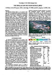
FIG. 1. (Color) Collection of stripped electrons during the injection of the H� beam at the SNS ring. The foil is placed in a dipole magnet, which is part of the injection bump. The lower pole surface of the magnet is extended downstream by about 20 cm so that the electrons are guided down to the electron collector.
094201-1
© 2005 The American Physical Society
L. WANG et al.
Phys. Rev. ST Accel. Beams 8, 094201 (2005)
upstream of the vertical plane by at least 65 mrad. The design’s field angle 220 mrad [3] is more than this requirement. The fringe field of the usual dipole magnet has the characteristics of a magnetic bottle: i.e., the field strength is stronger at the top and bottom than in the middle. To ensure the stripped electrons are not reflected upward before reaching the electron catcher, the lower pole surface of the magnet is extended downstream by about 20 cm. The field lines intersecting the foil enter the lower pole surface at roughly normal incidence. The field at the catcher is lower than that at the foil; therefore, the stripped electrons will not be reflected before reaching the electron collector. A mirror field was generated to reduce the reflection of the backscattered electrons in the Proton Storage Ring at Los Alamos National Laboratory (LANL-PSR) [4]. Figure 2 shows the trajectory of an electron initially generated from the foil’s center. Its gyration has a period 2�m0 �=eB of 0.29 ns and a radius �m0 �? =eB of 12 mm around the foil. When the electron descends from the foil, the guiding center slowly moves in the longitudinal direction along the magnetic-field line. III. OPTIMIZATION OF THE CATCHER The catcher has a serrated shape with slightly overhanging surface, as shown in Fig. 3. The real catcher consists of 4 pieces of the above pyramids so that the electrons that miss one pyramid can hit the next one. If a stripped electron hits the catcher’s top surface, the secondaries and backscattered electrons tend to rebound upward and return the beam’s chamber. To reduce this probability, the catcher’s position and geometry must be optimized so that the stripped electrons hit its front surface. It is found that this can be achieved by only optimizing the catcher’s position. Therefore, the catcher’s geometry is kept as the present design. The secondaries have only a few eV of energy and will, therefore, spiral tightly about the local magnetic-field line. The catcher’s overhanging surface then will prevent them from reentering the vacuum space.
FIG. 3. Geometry of the electron catcher. The angle � is chosen to be smaller than the slope angle of electron’s orbit in the vertical and longitudinal plane, which is about 24�.
However, the overhanging surface cannot completely prevent backscattered electrons from escaping into the attractive potential of the circulating beam because of their high energy and hence, big radius of gyration. However, the catcher’s structure ensures that the electrons hit it several times before they can reenter the beam’s chamber. The yield of backscattered electrons is smaller than unity, and most of them die out due to the reduction in their chances of reflection caused by their hitting the catcher’s surface multiple times (Fig. 4). The stripped electrons at the foil have a Gaussian distribution with an assumption of Gaussian injected beam distribution and cover 6 times the injection beam’s size with x0 � y0 � �2 mrad related to the injection beam. We simulated the effects of deviations in the foil’s longitudinal position (�z � �1:0 mm) to establish reasonable mechanical tolerances for installing the foil drive and the catcher. Figure 5 shows one example of the distribution of the stripped electrons at the foil and catcher; in this case, all stripped electrons hit its front surface, and are restricted to a small region at the catcher’s surface, with �X � 10 mm, �Y � 5 mm, �Z � 2 mm. Therefore, the heat load at the catcher is expected to be located in a small region. To ensure all stripped electrons hit the front surface, the position of the catcher needs to be optimized. In
FIG. 2. (Color) Trajectory of a stripped electron from the foil’s center. (a) Orbit in vertical and longitudinal plane and (b) in horizontal and longitudinal plane. The blue point is the position where the electron was emitted.
094201-2
STRIPPED ELECTRON COLLECTION AT THE . . .
Phys. Rev. ST Accel. Beams 8, 094201 (2005)
FIG. 4. (Color) Electron’s orbit showing the mechanism of capture. An electron first hits the front surface of the catcher and then is trapped inside the serrated edges of the catcher before it dies out. Y and Z are vertical and longitudinal directions.
principle, the best position of the catcher for maximum efficiency in the vertical and longitudinal direction is half of the pitch, and the diameter of the gyration motion, respectively, which are 12 and 23 mm (Fig. 2). The stripped electrons have a spread of 6� in the transverse phase space and 2 mm longitudinally. Therefore, the best zone will be smaller than the maximum zone given by a single particle’s motion. The success of capturing the electrons on the front surface also strongly depends on the geometry of the catcher. We carried out a three-dimensional simulation to find the best position of the catcher by scanning its position to ensure 100% stripped electrons hit its front face. Figure 6 depicts the simulated fraction of stripped electrons hitting the front surface of the catcher at various positions, which are shown by the coordinate of the catch-
FIG. 6. (Color) Catching efficiency with the catcher at various positions. Z and Y are the coordinates of the catcher’s tip. Catching efficiency is defined as the percentage of stripped electrons that hit the catcher’s front surface. The optimized zone center is (323; �91) with a zone about 10 and 15 mm in the vertical and longitudinal direction, respectively
er’s tip. The best place to position the catcher is about 10 and 15 mm in the vertical and longitudinal direction, respectively. If the foil’s position is changed, that of the electron catcher may need to be adjusted accordingly. For example, the injection beam’s position may have an error up to 2.0 mm transversely [5]. To minimize the probability of stripped electrons hitting the top surface of the catcher, its geometry also can be optimized. For example, the catcher’s width can be reduced (Z direction in Fig. 3) so that it is smaller than the diameter of the stripped electron’s gyration. The vertical size of the band of stripped electrons at the catcher’s surface can be increased with a bigger pitch attained by increasing the angle of the magnetic-field lines at the foil
FIG. 5. (Color) Distribution of stripped electrons at the foil (a) and at the catcher (b).
094201-3
L. WANG et al.
Phys. Rev. ST Accel. Beams 8, 094201 (2005) ���� � 1=�1 � cos��p ;
relative to the vertical direction. A hollow (increasing in Fig. 3) is helpful in trapping the backscattered electrons. IV. BACKSCATTERED ELECTRON CLOUD WITH A CARBON AND COPPER CATCHER A. Yield of backscattered electrons A fraction of the electrons that strike a target subsequently are scattered out of the specimen. These reemergent electrons collectively are known as backscattered electrons. The backscattered electron coefficient, �, is defined as the number of backscattered electrons divided by the number of electrons incident on the target. Generally, � increases with increasing atomic number. For example, Reuter [6] obtained a fit of Heinrich’s data [7] for 20 keV normal incident electrons: � � �0:0254 � 0:016Z � 0:000186Z2 � 8:310 � 10�7 Z3 ;
(1)
where Z is the atomic number. Figure 7 shows the backscattered electron coefficient of carbon, stainless steel, and copper with normal incidence electrons [8]. The backscattered electron yield of carbon is about 1 order-ofmagnitude smaller that of copper at the energy of 525 keV. Therefore, a carbon catcher can significantly reduce the number of backscattered electrons when stripped electrons hit it. Copper was chosen at the original design and carbon is finally used to reduce the reflected electrons. A comparison between carbon and copper catchers is made in this study to check the effect of electron’s yield. The backscattered electron coefficient increases with increasing of incident angle �. It is approximately described by [9]:
FIG. 7. (Color) Backscattered electron coefficient of carbon, stainless steel, and copper with normal incidence electrons.
(2)
with p � 9=Z1=2 for a pure element. Accordingly, the grazing incident effect is larger for low atomic-number materials. The angular distribution of the trajectories of the backscattered electrons as they emerge from the surface is described by a cosine function when the electron is incident normally on the surface: ���� � �0 cos�;
(3)
where � is the angle between the surface normal and the direction of the measurement, and �0 is the value of � along the surface normal. This cosine distribution is rotationally symmetric about the surface normal. The cosine distribution can be understood from the electron’s path. Consider an electron penetrating to a depth P0 before undergoing a large-angle collision, or being subjected to multiple scattering to reverse its direction of flight. The path that this electron must travel through the solid to reach the surface is related to the angle by P � P0 = cos�. Because of inelastic scattering, the electron loses energy along this path. The probability of an electron escaping from the specimen decreases as its energy falls, so, as the path it must travel lengthens, escape becomes less probable. For any angle �, the fraction of electrons which escape compared to those escaping along the shortest path P0 for � � 0 is given by N / 1=P / cos�. As the incident angle � is increased, the angular distribution of backscattered electrons changes, becoming asymmetrical about the incident axis. At high incident angles, the probability becomes very highly developed in the forward scattering events. Moreover, for high grazing incident electrons, the backscattered electrons tend to be emitted in a plane that is defined by the incident direction and the surface normal. In this study, we used the angular distribution of normal incidence [Eq. (3)] for all incident electrons. The stripped electrons strike the catcher with a high grazing angle due to the magnetic field. Therefore, our assumption increases the probability of backscattered electrons reentering the beam’s chamber. Hence, it is the worst possible case. Unlike the backscattered electrons, the angular and energy distributions of the true secondaries are independent of the angle of incidence. The secondaries at the catcher are confined inside its serrated structure by the magnetic field where the field lines are vertical, and therefore, there is no multipacting due to the secondaries’ low emission energy. If the stripped electrons hit the front surface of catcher, no secondaries can reenter the beam’s chamber. However, the backscattered electrons can do so if the emission angle is suitable. Carbon also has a lower yield of secondary electrons than copper. Therefore, using a carbon catcher is preferable considering both secondaries and backscattered electrons.
094201-4
STRIPPED ELECTRON COLLECTION AT THE . . .
Phys. Rev. ST Accel. Beams 8, 094201 (2005) catcher. With a carbon catcher, the electrons inside the beam’s chamber saturate quickly within 1.7 ns because only 0.34% of them can reenter the chamber. On the other hand, with a copper catcher 9.2% stripped electrons could reenter it. Therefore, with a copper catcher, there is a slow buildup and an electron cloud, as given in Fig. 8. Another simulation with EGS4 shows that about 15% electrons are reflected back towards the foil with a copper catcher [10]. The catcher position was not optimized at that calculation. The distribution of the electron cloud with a carbon and a copper catcher are shown in Figs. 9 and 10, respectively. The shape of electron cloud can be explained from the orbits of the stripped electrons depicted in Fig. 2. Electrons undergo about five periods of gyration before they reach the catcher. The reflected electrons are clearly shown in the case if a copper catcher (Fig. 10), but not for carbon (Fig. 9) due to its slow rate of accumulation.
FIG. 8. (Color) Electron buildup for the carbon and the copper catcher.
B. Electron cloud with carbon and copper catcher We simulated the effects of using both a carbon and a copper catcher with the same geometry and position as in Fig. 3. The stripped electrons take about 1.7 ns to reach the
C. Effect of a serrated surface To check the effect of the catcher’s serrated surface on the buildup of the electron cloud, we simulated the case of a carbon catcher with smooth flat surface parallel to the beam direction. We found that the electron cloud’s buildup was fast, as demonstrated in Fig. 8, because about 12% of the electrons can reenter beam’s chamber in this case. Therefore, the serrated surface plays an important role in
FIG. 9. (Color) Distributions of electron cloud with a carbon catcher. Distribution (a) in horizontal and vertical plane (b) in vertical and longitudinal plane; (c) in horizontal and longitudinal plane.
094201-5
L. WANG et al.
Phys. Rev. ST Accel. Beams 8, 094201 (2005)
FIG. 10. (Color) Distributions electron cloud with a copper catcher. Distribution (a) in horizontal and vertical plane (b) in vertical and longitudinal plane; (c) in horizontal and longitudinal plane.
reducing the numbers of reflected electrons due to the multiple scattering inside the serrated structure.
interact with the circulating beam. The peak beam potential is
D. Mirror-field effect
� � � b �� 1 � 2 ln ; 4�"0 a
The magnetic field at the top of the vacuum chamber is stronger than at the bottom, but the difference is small, with the ratio of the minimum and maximum field being 0.9. The mirror field can trap electrons in the weak field region. If an electron from the catcher reenters the vacuum chamber, the condition for it to be reflected by the stronger field at the foil is B E? �at collector� > collector ; Bfoil E
(4)
where E? and E are the kinetic energy of gyration motion and total kinetic energy. The above condition is not satisfied for most reentering electrons. Therefore, they cannot be reflected by the mirror field, and so will hit the top surface of the chamber (Fig. 10). E. Beam effect It takes 1.7 ns for a stripped electron to get the catcher. The beam’s effects on electron’s energy and orbit are negligible during that period. If some backscattered electrons and secondaries enter the beam’s chamber, they will
(5)
where a and b are the radius of the beam and chamber, and � is the beam line density. The peak beam potential is 10 keV. Therefore, the beam has a negligible effect on the backscattered electrons, which typically have energies of hundreds of keVs. In a simulation, we compared the buildup of the electron cloud, in a design with the carbon catcher, with and without the circulating beam. We found no difference between the two cases, implying that the beam’s effect is negligible and there is no multipacting. F. Secondary electrons induced by the impacting of the injection and circulating beams These secondaries have a low emission energy (tens of eV), and hence, they will circulate around the magneticfield lines with small radius less than 0.1 mm. Unlike the stripped electrons, the secondaries may go up or down along the magnetic-field lines. They will be vertically trapped by the circulating beam and move downstream longitudinally due to the cross-field drift
094201-6
STRIPPED ELECTRON COLLECTION AT THE . . .
Phys. Rev. ST Accel. Beams 8, 094201 (2005) and longitudinal directions, respectively. A carbon catcher can capture 99% of the stripped electrons. The secondary electrons induced by the impacting of the injection and circulating beams are vertically trapped by the circulating beam and move downstream up to 0.2 m during the passage of one bunch. However, the number of these electrons is small due to low electron yield and the trapping effect. ACKNOWLEDGMENTS
FIG. 11. (Color) The orbit of a trapped electron. The electron is emitted from the foil at the peak of the beam’s profile. It hits the beam’s pipe at the bunch tail. The red dot is its emission position, the circulating beam is in �Z direction.
��
E�B ; B2
(6)
where E is beam’s field. The electrons are released at the end of bunch. They move up or down along the magneticfield lines and hit the surface of the pipe during the bunch gap. Figure 11 shows a sample of the electrons’s orbit. An electron can move downstream up to 0.2 m during one bunch’s passage. As a result, the lost electrons at the pipe’s surface form a longitudinal strip with a horizontal position at the foil’s center. These electrons do not exhibit multipacting due to their low-energy gain and trapping. The buildup of these electrons is similar with that of electrons due to ionization [1]: an electron cloud accumulates during the beam’s passage due to the trapping and has a peak at the bunch tail. The simulated peak electron line density after one bunch’s passage is 0:05 nC=m with an electron yield of 0.006 [11]. V. CONCLUSION The injection foil is placed in a magnetic field, which guides the stripped electrons down to the electron catcher. The catcher has a serrated shape with a slightly overhanging surface so that electrons can be confined inside and hit the catcher surface several times before they die out or are reflected. The stripped electrons are restricted to a small region at the catcher’s surface with �X � 10 mm, �Y � 5 mm, �Z � 2 mm. Electron collection is sensitive to the catcher’s geometry, position, and material. The good catcher zone has 10 and 15 mm widths in the vertical
We are indebted to our colleagues on SNS project and electron-cloud community, especially J. Alduino, A. Chao, P. He, F. M. Hemmer, J. A. Holmes, R. Macek, W. McGahern, B. Mullany, M. Plum, C. Prior, A. Shishlo, J. Tuozzolo, and F. Zimmermann. The SNS is managed by UT-Battelle, LLC, under Contract No. DE-AC0500OR22725 for the U.S. Department of Energy. SNS is a partnership of six national laboratories: Argonne, Brookhaven, Jefferson, Lawrence Berkeley, Los Alamos, and Oak Ridge.
[1] L. Wang, M. Blaskiewicz, J. Wei, W. T. Weng, K. Ohmi, and R. Macek, Phys. Rev. E 70, 036501 (2004). [2] Y. Y. Lee, G. Mahler, W. Meng, D. Raparia, L. Wang, and J. Wei, in Proceedings of the Particle Accelerator Conference, Knoxville, Tennessee, 2005 (to be published). [3] J. Beebe-Wang, Y. Y. Lee, D. Raparia, and J. Wei, in Proceedings of the 2001 Particle Accelerator Conference, P1508, Chicago (IEEE, Piscataway, NJ, 2001). [4] D. B. Barlow, A. J. Jason, F. Neri, and P. L. Walstrom, IEEE Trans. Magn. 32, 2179 (1996). [5] D. T. Abell, Y. Y. Lee, and W. Meng, in Proceedings of the 2000 European Particle Accelerator Conference, Vienna (EPS-IGA/CERN, Geneva, 2000), p. 2107. [6] W. Reuter, in Proceedings of VIth International Conference on X-Ray Optics and Microanalysis, Osaka, Japan (University of Tokyo Press, 1972), pp. 121–130. [7] K. F. J. Heinrich, in Proceedings of 4th International Conference on X-Ray Optics and Microanalysis, edited by R. Castaing, P. Deschamps, and J. Philibert (Hermann, Paris, 1965), pp. 159–167. [8] T. Tabata, R. Ito, and S. Okabe, Nucl. Instrum. Methods 94, 509 (1971). [9] F. Arnal, P. Verdier, and P. Vincesini, C. R. Acad. Sci. 268, 1526 (1969). [10] W. R. Nelson, H. Hirayama, and D. W. O. Rogers, Stanford Linear Accelerator Center Report No. SLAC-265, 1985. [11] J. Wei, Rev. Mod. Phys. 75, 1383 (2003).
094201-7