IEEE TRANSACTIONS ON INDUSTRIAL ELECTRONICS, VOL. 56, NO. 8, AUGUST 2009
3195
Strobe Imaging System for Digital Image-Based Elasto-Tomography Breast Cancer Screening Christopher E. Hann, J. Geoffrey Chase, XiaoQi Chen, Senior Member, IEEE, Crispen Berg, Richard G. Brown, and Rodney B. Elliot
Abstract—Digital image-based elasto-tomography technology relies on obtaining high-resolution images of a breasts surface under high-frequency actuation, typically in the range of 50– 100 Hz. Off-the-shelf digital cameras and imaging elements are unable to capture images directly at these speeds. A method based on strobe imaging is presented for obtaining the required high-speed image capture at a resolution of 1280 × 1024 pixels and actuation frequency of 100 Hz. The final working system produced images that enabled effective 3-D motion tracking of the surface of a silicon phantom. The motion is tracked accurately using a novel Euclidean Invariant signature method. Index Terms—Digital Image-based Elasto-Tomography (DIET), euclidean invariant signature, strobe imaging, surface motion tracking.
I. I NTRODUCTION
B
REAST cancer is a significant health problem in both developed and developing countries [1]. Mammography is currently the standard for breast cancer screening. However, it can cause significant discomfort to patients, requires radiation exposure, and interpretation of images is subjective, potentially leading to misdiagnosis and false positives. Digital Image-based Elasto-Tomography (DIET) is an emerging technology for noninvasive breast cancer screening. The DIET system uses digital imaging of an actuated breast surface to determine tissue surface motion from a specified input. It then reconstructs the 3-D internal tissue stiffness distribution from that motion. The internal distribution of stiffness is reconstructed using boundary element method or finite element method. Regions of high stiffness suggest cancer since cancerous tissue is between three and ten times stiffer than healthy tissue in the breast [2]–[4]. This approach eliminates the need for X rays and excessive potentially painful compression of the breast [5] as required in a mammogram. Hence, screening could start much younger and might enjoy greater compliance [6]. This system is designed to capture high-frequency rapid motion of large numbers of fiducial markers. Such tracking would thus enable motion sensing by a variety of feature Manuscript received February 2, 2008; revised May 12, 2009. First published June 5, 2009; current version published July 24, 2009. The authors are with the Department of Mechanical Engineering, University of Canterbury, Christchurch 8140, New Zealand (e-mail: Chris.
[email protected];
[email protected]; xiaoqi.chen@ canterbury.ac.nz). Color versions of one or more of the figures in this paper are available online at http://ieeexplore.ieee.org. Digital Object Identifier 10.1109/TIE.2009.2023643
identification and motion tracking algorithms using epipolar and nearest neighbor constraints [7], [8]. Thus, this paper represents the hardware instantiation designed to optimally support such emerging industrial focused motion tracking and sensing algorithms. For optimal 3-D tissue reconstruction, the breast is actuated at 50–100 Hz [9], [10]. This frequency is well outside the frequencies of biological processes, such as breathing and heart rate. The amplitude of actuation is about 1–5 mm, which takes into account patient comfort, and limitations on actuator and motion measurements. At these high frequencies, image capture is therefore a challenging task, since clear crisp images at high resolution are required for high density, accurate velocity, and displacement vectors to be obtained. This requirement for the cameras puts the array of pixels required in the super video graphics array (SVGA) range (1264 × 1016), at minimum. Based on prior analysis of field of view size and desired spatial resolution, images of 4–16 Mpixels will be required [5]. Recently, CMOS technology has developed to the point of cameras reaching 500 images per second at a resolution of 1280 × 1024 [11]. This is rather limited for the DIET system as it would provide, at maximum, ten images of a cycle at 50 Hz and only five images of a cycle at 100 Hz. Furthermore, this technology is not “off the shelf,” thus is not readily available, and there is still limits on cost and the issue of synchronizing a number of cameras. The latest digital camera on the market can achieve 6315 frames/s (fps) at a resolution of 1280 × 800 [12], but again the high cost limits its use in DIET. The resolution is also still on the low side, forcing more cameras to be used to capture all the required motion on a breast, further increasing costs and with the relatively large size would compromise the portability of the system. There are also many other examples of fast CMOS imaging at low resolutions. This paper develops and implements a method for combining a stroboscope with “off-the-shelf” CMOS imaging sensors to enable high-frequency high-resolution image capture for the DIET system. In particular, the KAC-9648 SVGA CMOS imaging sensors from Kodak are used, and the image capture method developed in this paper is shown to efficiently and automatically grab images from the breast with actuation frequencies of 50–100 Hz. As a result, the need for very expensive high-speed highframe rate image capture, which often comes only at lesser resolution, is avoided. In particular, the approach presented allows low-cost standard imaging sensors to be used. These sensors are growing in size (in megapixels) and speed on an annual base, so the approach presented allows this technology
0278-0046/$26.00 © 2009 IEEE
Authorized licensed use limited to: University of Canterbury. Downloaded on July 29, 2009 at 23:22 from IEEE Xplore. Restrictions apply.
3196
IEEE TRANSACTIONS ON INDUSTRIAL ELECTRONICS, VOL. 56, NO. 8, AUGUST 2009
to be utilized as it appears rather than waiting for it to be used in high-speed image capture systems. The prototype apparatus presented uses two imaging sensors in combination with frame grabbers and a dSpace control system, to produce an automated image capture system. The system integrates a precision-controlled strobe lighting system to selectively capture sinusoids at different points in the sinusoidal cycle of response. The final working system produced images that enabled effective 3-D motion tracking of the surface of a silicon phantom actuated at 100 Hz. The surface of the phantom was strobed at preselected phases from 0◦ to 360◦ , and an image was captured for each phase. The times at which image capture occurred were calculated for a phase lag increment of 10◦ resulting in an image effectively every 0.00028 s for the actuator cycle of 0.01 s. The comparison of the actual trigger times and preselected ideal trigger times gave a mean absolute error of 1.4%, thus demonstrating the accuracy of the final system. The overall approach is validated by tracking motion of artificially placed fiducial points on the surface of a silicon gel phantom. The motion tracking is performed based on a novel Euclidean Invariant signature [13], which compacts a large amount of information into a simple form. The signature is effectively invariant to the phantom’s motion, thus the process of identifying points between images is transformed into a dramatically simpler problem of identifying the overlaps of two signatures. The end result is the ability to track large numbers of points very accurately and with minimal computation required. Both cameras delivered similar results with over 90% of points tracked to within 1%–2%. This level of accuracy confirms the ability to effectively accurately reconstruct the stiffness as validated in other related studies. In summary, by creating a novel approach that does not rely on ultrahigh speed emerging imaging technologies, this DIET approach can offer higher resolution than these solutions using off-the-shelf digital imaging components. As a result, the overall system is potentially no more costly than current commercial digital cameras, and thus can provide a potentially very low-cost medical diagnostic that also has, as a consequence of the novel design approach taken here, a higher resolution than typical high-speed imaging systems. This last aspect thus offers the high-precision motion sensing necessary to enable the DIET concept [5], [14]. II. I MAGE C APTURE S YSTEM Fig. 1 shows a picture of the system. The setup for the new image capture system developed is divided into two main sections: image capture, and actuator and trigger control. The overall layout for the image capture and related trigger and data lines is shown in Fig. 2. The image capture computer (ICC) handles all the capturing and storing of the digital images. The ICC contains two PCI frame grabbers and an I2C adapter. The PCI frame grabbers capture all the image data arriving from the imaging sensors along the pixel data lines, as shown in Fig. 2. Two Kodak KAC-9648 color image sensors are used in this apparatus. Each sensor produces image data output in the form of 10-b per pixel
Fig. 1.
Image capture setup.
Fig. 2.
Layout for the digital image capture system.
at a resolution of 1280 × 1024. Communication between the ICC and the camera is carried out via the I2C adapter. The adapter has two digital lines coming out of it, the first is the serial data line and the second is the serial clock line. Both cameras are connected in parallel to these two serial lines and each has a unique bus address. For example, when the I2C adapter communicates with the left camera, it first transmits the bus address of the left camera. This puts the camera in a state to listen for any information arriving down the two serial lines. This information could be a change in the active window size required by the user or same other input. The right camera then ignores this information since the I2C adapter is only “addressing” the left camera. There are two camera configurations required, involving a communication between the I2C adapter and the cameras. The first camera configuration is the initialization of the digital cameras, which enables them to be compatible with the frame grabbers. The result of this initialization is a continuous stream
Authorized licensed use limited to: University of Canterbury. Downloaded on July 29, 2009 at 23:22 from IEEE Xplore. Restrictions apply.
HANN et al.: STROBE IMAGING SYSTEM FOR DIET BREAST CANCER SCREENING
3197
Fig. 5. Hierarchy of control for the dSpace setup.
Fig. 3.
Process of strobe trigger by the camera.
Fig. 4.
Process of strobe trigger by the camera.
of video data, which is displayed on the screen and enables the user to adjust color gains, focus, camera position, and aperture size as required. The second configuration puts the cameras into a state where they are able to receive a digital pulse from dSpace, which triggers the frame exposure and strobe activation. Specifically, there is an input pin and an output pin on the sensor that is automatically configured after instructions from the I2C adaptor, as shown in Fig. 3. The first pin is called a triggered snap pin, which receives the pulse from dSpace and starts frame exposure. The second pin is called an external sync, which supplies a pulse to activate the strobe. The precise timing of the strobe trigger from the camera is preset and cannot be changed by the user. After both camera configurations are performed, enabling compatibility with the frame grabbers and triggering of the frame exposure and strobe activation, the cameras are ready for image capture of the actuated test phantom. III. ACTUATOR AND S TROBE T RIGGER C ONTROL The setup for the actuator and trigger control is shown in Fig. 4. The dSpace computer uses Simulink from Matlab to create a system for controlling the input and output signals. The system for processing the signals is built up from blocks, similar to a wiring diagram, where Simulink blocks are connected together to perform its portion of the image capture task on the dSpace module.
The portion of the image capture process for which the dSpace is responsible is the generation and synchronizing of signals sent to the actuator and necessary trigger signals. Once the diagram is ready, it is automatically transferred to a C code format, uploaded to dSpace, and then run by dSpace in realtime inside the dSpace module. The settings in the Simulink diagram can be adjusted in real time using the dSpace software ControlDesk. ControlDesk makes it possible to automatically perform real-time adjustments of the working embedded code in the dSpace module. For example, resetting the trigger signals to the frame grabbers and cameras, and real-time adjustment of the actuator amplitude. ControlDesk also allows trigger settings to be modified via a user built project interface. The rounded boxes in Fig. 4 represent the programs’ interactions with the hardware where ControlDesk and Matlab are constantly talking to one another and adjusting the settings in the dSpace module. The programming language used to automate ControlDesk is known as Python. Python is a high-level scripting, interpreted, and interactive object-oriented programming language. The Python code is used to talk to the ICC and automate the sending of the trigger signals. The hierarchy for the operation of Simulink, ControlDesk, and Python is shown in Fig. 5. A 50–100-Hz sinusoidally (or periodically) actuated silicon phantom would require 50–100 fps in the imaging sensors. Since the frame rates of the CMOS imaging sensors for this project have a maximum rate of 18 fps at full resolution, it is therefore not possible to directly image the phantom. To overcome this problem, the high-speed phantom is strobed at specific points in its motion, thus effectively rendering the object “stationary” at that point in its resulting sinusoidal periodic response. In Fig. 6 is an example of 12 different phase angles in the actuator’s cycle where a user requires an image of the phantom. By introducing a phase shift between the actuators motion and the point of triggering the strobe, the object can be made “stationary” at each of these 12 user-defined points in its response and thus an image taken. In this example, the phase shifts are at increments of 30◦ labeled 1 to 12 in Fig. 6. A similar process could be used to capture images of an object at any predefined points in an actuator cycle for any actuator frequency. For the DIET system, this provides the required ability to capture a sequence of high-resolution images of a 50–100-Hzactuated silicon breast phantom describing the displacement response throughout a 360◦ cycle. At each point, the tissue surface motion is imaged and captured. From this data, the magnitude and phase of the response relative to the input can be
Authorized licensed use limited to: University of Canterbury. Downloaded on July 29, 2009 at 23:22 from IEEE Xplore. Restrictions apply.
3198
IEEE TRANSACTIONS ON INDUSTRIAL ELECTRONICS, VOL. 56, NO. 8, AUGUST 2009
Fig. 6. Example of a 12-Hz command signal that would drive the sinusoidal motion of an actuator.
Fig. 8.
New strobe trigger setup.
seven images at a phase lag of 0◦ and a 100-Hz signal. In other words, the camera is not designed for precision strobing greater than 10-Hz image capture frequency. A second problem was also discovered, which involved external synchronous (sync) time variations between the two cameras. For example, triggering the strobe using the right camera resulted in partial images from the left camera on random phase lags. This problem was due to the left camera not being ready for the strobe to flash at the same time as the right camera, even though the dSpace trigger pulse was sent to the cameras at the same time. V. C ORRECTED I MAGE R ESULTS In this section, the following problems are addressed and results presented:
Fig. 7. Graph of the dSpace trigger pulse/strobe trigger pulse time period.
readily obtained as it is assumed that the small sinusoidal inputs result in a sinusoidal response at the (steady-state) frequency. The actuator used in this system has a linear transducer (LVDT), built into the core of the actuator, which sends data back to the dSpace module (see Fig. 4). IV. P RELIMINARY I MAGE C APTURE R ESULTS In the initial tests of the image capture setup, the time period between when camera fired the strobe flash and the camera received the trigger pulse to snap a frame was inconsistent and unpredictable. This inconsistency makes it very difficult to align the strobe trigger with the phase position in the actuators cycle. Specifically, consider the case of the actuator moving at a frequency of 100 Hz, which is the maximum frequency required of this image capture system. Thus, the actuator and silicon phantom move through a 360◦ cycle every 0.01 s. The problem is that while the time periods between the dSpace trigger pulse and the strobe trigger pulse are consistent at a time resolution of 0.1 s; it can fluctuate randomly over the finer resolution of 0.01 s. This behavior is shown in Fig. 7 for the left camera over
1) inconsistencies in required strobe trigger between cameras; 2) an inconsistent time period, at the required time resolution, between the dSpace trigger pulse and the strobe trigger pulse. Both of these problems are addressed simultaneously with the introduction of solid-state AND gate and a feed back pulse to the dSpace module, which triggers the strobe flash. As shown in Fig. 8, the solid-state AND gate is attached to the two external sync lines from each camera, and this addition aligns the two pulses into one coherent pulse that is fed into the dSpace module. The single coherent external pulse sent to the dSpace module from the AND gate is then aligned with the rising edge of the now phase-lagged LVDT signal, which is then passed back out to trigger the strobe. The single external strobe trigger is aligned in much the same way as the camera snap trigger pulse using flip-flops Simulink blocks. The strobe itself actually triggers on the falling edge of the trigger pulse and not the rising edge because of the way the strobe was designed by the manufacturer. Due to the falling edge trigger, a “NOT” gate is used to invert the edge. The implementation of this “NOT” gate achieves the result shown in Fig. 9.
Authorized licensed use limited to: University of Canterbury. Downloaded on July 29, 2009 at 23:22 from IEEE Xplore. Restrictions apply.
HANN et al.: STROBE IMAGING SYSTEM FOR DIET BREAST CANCER SCREENING
Fig. 9.
3199
Timing of the modified strobe trigger.
Fig. 11. Actual position of the actuator compared to an Ideal position at a snapshot of the actuators motion taken at 1.8207 s.
Fig. 10. Comparison of the average strobe triggering times over the four image capture runs compared with the ideal triggering times.
Each rising edge of the square wave LVDT lagged signal occurs at a specific point in the actuators motion. This rising edge is moved to other positions in the actuators motion, by adjusting the phase lag desired. It is this rising edge that the strobe must trigger on to capture the actuator at that specific position. The external synchronous from the cameras notifies the image capture system that the cameras are ready for the strobe flash, but the flash must occur on the rising edge of the lagged LVDT signal. Thus, the external synch must remain high until the next rising edge in the lagged LVDT signal, which is at 0.01 s intervals for 100-Hz actuation. Since the external sync therefore may remain high for ∼0.25–0.3 s, there is plenty of time for the strobe to receive a rising edge and thus trigger a camera flash. The result of the solid-state AND gate and feedback pulse to the dSpace module applied to the apparatus of Fig. 2, allows the strobe to trigger at points close to the ideal trigger times, as shown in Fig. 10. It should also be noted that the actuator has imperfections or error in its motion. A snap shot of the actuators motion at t = 1.8207 s compared with an ideal case shown in Fig. 11, shows a time period where the difference in the two waveforms is at a minimum corresponding to the best achievable actuator
Fig. 12. Mean actuator displacement compared with the ideal actuator displacement over 20 000 actuator cycles.
motion. The variation in frequency for Fig. 12 is between 98 and 100 Hz or less than 2%. An average of 20 000 actuator waveforms were taken, and the result is shown in Fig. 12 showing that a larger error dominates the motion. Since Figs. 11 and 12 involve direct measurements of the actuator displacement, errors can be attributed to the dynamics of the actuator itself. In other words, there are physical limitations in the current actuator. Further experimental work and potential improvements need to be done in the future. In practice, images of a silicon phantom’s displacement response to one specific period of the actuator, as in Fig. 11, for example, cannot be achieved. As discussed earlier, the way to build up one complete cycle of the actuated silicon phantom, is to strobe at predefined phase angles and capture an image at each strobed point in time. To further validate the method, the
Authorized licensed use limited to: University of Canterbury. Downloaded on July 29, 2009 at 23:22 from IEEE Xplore. Restrictions apply.
3200
IEEE TRANSACTIONS ON INDUSTRIAL ELECTRONICS, VOL. 56, NO. 8, AUGUST 2009
Fig. 14.
Silicon phantom used in the experiments and its dimensions.
Fig. 13. Compiled actuator displacements at the time of the strobe firing, compared with an ideal actuators displacement at that point.
phase lag increment is chosen to be 10◦ so that strobing occurs every 0.00028 s of the 0.01-s cycle. The actuator displacements at the time of the strobe firing are shown in Fig. 13. Note that the specific times that the images are taken can vary significantly between runs. However, relative to the 0.01-s cycle, the image capture times are very consistent, as shown in Fig. 10. For example, the first ten image capture times in Fig. 13 are
Fig. 15. Two images of the silicon phantom from the left camera with 54 black dots on the surface moving at 1.2 mm of amplitude.
t = [5.541, 14.5413, 24.3915, 34.1817, 44.0121, 53.8224, 63.6525, 73.4427, 83, 2932, 93.0834]. With respect to the 0.01-s cycle, the ten image capture times are effectively t = [0.0002, 0.0005, 0.0007, 0.001, 0.0013, 0.0016, 0.0017, 0.002, 0.0024, 0.0026]. These values are very close to multiples of 0.00028, as required. The results in Fig. 13 show similar behavior to Figs. 11 and 12, further demonstrating the accuracy of the strobe and camera trigger system. VI. S URFACE M OTION T RACKING The system is first tested with a reasonably small number of points using a silicon phantom moulded in a cylindrical shape. The silicon phantom used in this experiment is a two-part mix solid silicon elastomer, and is shown in Fig. 14. This silicon polymer was chosen because of similarities with the elastic properties of human tissue. Thirty-six images are taken of the silicon phantom corresponding to 60◦ intervals from 0◦ to 300◦ (see Fig. 15). The frequency of actuation is 100 Hz with amplitude of 1.2 mm. On the face common to both cameras, there are 54 black dots, which are used to help track the surface motion of the phantom. The camera was calibrated beforehand by corresponding known points on a precisely ma-
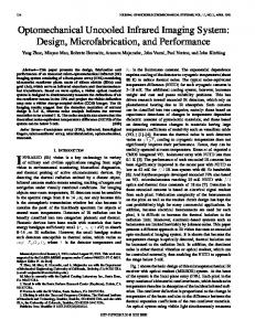
Fig. 16. (a) Silicone gel phantom with colored speckles. (b) Detected RGB points.
chined calibration object with their image locations and solving for the projection matrix. To validate the image capture system, the black dots in Fig. 15 are used to track the displacement of the moving surface of the phantom. The motion-tracking algorithm is based on [13]. All points were tracked accurately and the 3-D mapped positions of the dots agreed well visually to the shape of the phantom (results not shown). The method is now tested on a new silicon phantom with significantly more points. Approximately 750 colored points— 100 red, 300 blue, and 350 green—were placed randomly on the phantom, as shown in Fig. 16(a). The phantom actuated at 50 Hz, with 1-mm peak-to-peak sinusoid at the actuator plate. A set of 20 images was captured to cover the entire sinusoid at 18◦ phase differences. The different colored regions were found by thresholding the red, green, and blue (RGB) image, and the positions of the points were found by the centroids of the colored blobs. An example of the extracted points is shown in Fig. 16(b). Note that with this simple approach not all the image points are recognized, however this is not a concern as only a certain density of points is needed to be matched, rather than every individual point.
Authorized licensed use limited to: University of Canterbury. Downloaded on July 29, 2009 at 23:22 from IEEE Xplore. Restrictions apply.
HANN et al.: STROBE IMAGING SYSTEM FOR DIET BREAST CANCER SCREENING
3201
Fig. 19. (a) Detected motion of a silicon phantom with no inclusion, from a pair of cameras. The motion is close to vertical, but is slightly distorted from the 2-D projection of the 3-D surface. (b) Detected motion of a silicon phantom with an ∼1-cm3 inclusion, from a pair of cameras. The trajectories can be seen circling the inclusion marked with a red cross.
Fig. 17. Example of tracked points from gel phantom experiment, with matched pairs connected with an arrow. All the points are shown in (a) while (b) is a close-up.
Fig. 18. Silicon phantom under actuation with colored dots applied.
The points in Fig. 16 were then tracked using the Euclidean Invariant Signature approach of [13]. Fig. 17 shows an example of the motion undergone by the matched points. Over 90% of points in the images from both cameras were tracked successfully. Based on an estimate of the calibration accuracy of the cameras, the accuracy of tracking amounted to between 1% and 2% of the amplitude response for the silicon phantom. The close-up of Fig. 17(b) demonstrates that the number of tracked points is more than enough to cover the surface. VII. M ULTIPLE C AMERAS AND AN I NCLUSION As proof of concept the same capture system and approach has been applied to four standard consumer Canon Powershot G5 cameras operating at 2 Mpixels. Each camera is fitted with an LED ring flash to improve image quality. Some tests have been carried out on silicon breast-shaped phantom actuated at 80 Hz, with an amplitude of 0.75 mm. Twenty images were taken at even phase increments over the cycle from each camera. Fig. 18 shows the silicon phantom. Using the Euclidean Invariant algorithm [13], the motion of the cameras has been tracked. The same approach was used to track the surface motion of a silicon phantom with an ∼1-cm3 inclusion. Fig. 19(a) shows a 2-D projection of the point motion trajectories with no inclusion and Fig. 19(b) shows the result with the inclusion.
In each case, a pair of cameras is used to capture the motion. The trajectories can be seen circling the location of the hard inclusion in Fig. 19(b) which has very little motion due to the high stiffness. Note that the apparent curves in Fig. 19(a) are due to the warping that happens after the projection. Future work will test the ability of this multiview imaging system to detect a variety of inclusions both near the surface and nearer the center using the finite element approach [5] and will investigate the minimum number of cameras required for sufficient accuracy. This will include using potentially six–ten CMOS cameras and/or other cameras as required. This paper will include tests on how small a tumor can be detected and will be reported in future papers. This paper on breast phantoms will lead to eventually clinical trials in the future, and the development of a breast cancer screening system longer term. VIII. C ONCLUSION A high-speed digital image capture system for tracking highfrequency actuations of a silicon phantom has been presented. The key feature of the system is that it enables a combination of a strobe and off-the-shelf cameras to achieve very high frame rates in image capture, not typically available at present. The image capture system was successfully tested on silicon phantoms with and without inclusions, moving at frequencies ranging from 50 to 100 Hz and with amplitudes from 0.5 to 1.2 mm. Accurate surface motion tracking is obtained at a high image resolution of 1280 × 1024. The image capture system also included functionality for the manipulation of color gains and active windows making the system more adaptive to testing and laboratory conditions. An important feature was the use of the dSpace control system module, which allowed the image capture process to take place outside of the Windows operating system message loops. This approach greatly increased the control over the timing of the events that go into capturing the high-speed images. It also matches any such commercial system, which would also use a similar embedded operating system. The in-house construction of the digital cameras using Kodak’s KAC-9648 CMOS imaging sensor allows a reduction in complex circuitry in the camera design, simplifying making the future development and production of the digital cameras easier. The comparison between the ideal and actual strobe triggering times showed that the strobe was correctly triggered at the
Authorized licensed use limited to: University of Canterbury. Downloaded on July 29, 2009 at 23:22 from IEEE Xplore. Restrictions apply.
3202
IEEE TRANSACTIONS ON INDUSTRIAL ELECTRONICS, VOL. 56, NO. 8, AUGUST 2009
required predefined phase angles with a mean absolute error of about 1.4%. There were variations of the displacement of the actuator compared with the ideal actuator displacement at which the strobe triggers corresponding to a variation of 95– 100 Hz within one image capture cycle. However, this displacement error was shown to be attributable to the dynamic properties of the actuator itself. For example, internal friction and the returning frequency of the LVDT signal varying slightly either side of the reference frequency for the introduction of the phase lag. A more accurate actuator will resolve these issues. R EFERENCES [1] M. F. Bultitude and I. S. Fentiman, “Breast cancer in older women,” Int. J. Clin. Pract., vol. 56, no. 8, pp. 588–590, Oct. 2002. [2] A. Samani, J. Bishop, C. Luginbuhl, and D. B. Plewes, “Measuring the elastic modulus of ex-vivo small tissue samples,” Phys. Med. Biol., vol. 48, no. 14, pp. 2183–2198, Jul. 2003. [3] T. A. Krouskop, T. M. Wheeler, F. Kallel, B. S. Garra, and T. Hall, “Elastic moduli of breast and prostate tissues under compression,” Ultrason. Imag., vol. 20, no. 4, pp. 260–274, Oct. 1998. [4] P. W. Wellman and R. D. Howe, “Breast tissue stiffness in compression is correlated to histological diagnosis,” Harvard BioRobotics Lab., Cambridge, MA, 2000. [5] A. Peters, A. Milsant, J. Rouze, L. Ray, J. G. Chase, and E. E. W. Houten, “Digital image-based elasto-tomography: Proof of concept studies for surface based mechanical property reconstruction,” Jpn. Soc. Mech. Eng. Int. J. Ser. C, vol. 47, no. 4, pp. 1117–1123, 2005. [6] M. Robertson, “Commercialisation and IP strategies for digital imagebased elasto-tomography (DIET),” M.S. thesis, Univ. Canterbury, Christchurch, New Zealand, 2005. [7] A. D. Cheok, Y. Qiu, K. Xu, and K. G. Kumar, “Combined wireless hardware and real-time computer vision interface for tangible mixed reality,” IEEE Trans. Ind. Electron., vol. 54, no. 4, pp. 2174–2189, Aug. 2007. [8] R. Brown, “High speed 3D motion sensing for a digital image-based elasto tomography breast cancer screening system,” Ph.D. dissertation, Univ. Canterbury, Christchurch, New Zealand, 2008. [9] E. E. W. Van Houten, K. D. Paulsen, M. I. Miga, F. E. Kennedy, and J. B. Weaver, “An overlapping subzone technique for MR based elastic property reconstruction,” Magn. Reson. Med., vol. 42, no. 4, pp. 779–786, Oct. 1999. [10] E. E. W. Van Houten, J. B. Weaver, M. I. Miga, F. E. Kennedy, and K. D. Paulsen, “Elasticity reconstruction from experimental MR displacement data: Initial experience with an overlapping sub-zone finite element inversion process,” Med. Phys., vol. 27, no. 1, pp. 101–107, Jan. 2000. [11] B. Wilburn, N. Joshi, V. Vaish, M. Levoy, and M. Horowitz, “High-speed videography using a dense camera array,” in Proc. IEEE Comput. Soc. Conf. CVPR, 2004, vol. 2, pp. 294–301. [12] R. Mosqueron, J. Dubois, and M. Paindavoine, “High-speed smart camera with high resolution,” EURASIP J. Embedded Syst., vol. 2007, no. 1, pp. 23–38, Jan. 2007. [13] R. G. Brown, C. E. Hann, J. G. Chase, and L. Ray, “Discrete colour-based Euclidean-invariant signatures for feature tracking in a DIET breast cancer screening system,” in Proc SPIE Med. Imag. Conf.—Physiol., Function, Struct. Med. Imag., San Diego, CA, 2007, p. 12. [14] A. Peters, J. G. Chase, and E. E. W. Van Houten, “Digital image elastotomography: Mechanical property estimation of silicone phantoms,” Med. Biol. Eng. Comput., vol. 46, no. 3, pp. 205–212, Mar. 2008.
Christopher E. Hann received the B.Sc. (Hons.) degree (with first-class honors) and Ph.D. degree in mathematics from the University of Canterbury, Christchurch, New Zealand, in 1996 and 2001, respectively. He was a Mathematics Teaching Fellow until 2003, when he joined the Department of Mechanical Engineering, University of Canterbury, in 2004, as a Postdoctorate, where he has been a Sir Charles Hercus Health Research Fellow since 2007. His research includes biomedical systems and parameter identification, control systems, and computer vision. He has published over 150 refereed journal and conference papers, is an inventor on several patents and is on the editorial board for a bioengineering journal.
J. Geoffrey Chase received the B.S. degree in mechanical engineering from Case Western Reserve University, Cleveland, OH, in 1986, and the M.S. and Ph.D. degrees in mechanical and civil engineering from Stanford University, Stanford, CA, in 1991 and 1996, respectively. He spent six years with General Motors and five years consulting with Silicon Valley. Since 2000, he has been with the University of Canterbury, Christchurch, New Zealand. His research includes the following: biomedical systems/devices, structural dynamics/vibrations, automatic control, MEMS/microfabrication, and embedded systems. He has published over 320 refereed journal and conference papers, is an inventor on over ten patents and is on the editorial board of three bioengineering journals.
XiaoQi Chen (SM’07) received the B.E. degree from South China University of Technology, Guangzhou, China, in 1984, the M.Sc. degree from Brunel University, Uxbridge, U.K., in 1986, and the Ph.D. degree from the University of Liverpool, Liverpool, U.K., in 1989. From 1989 to 1990, he was Senior Research Assistant with the University of Durhamm. From 1990 to 1992, he was a Research Fellow with Brunel University. From 1992 to 2006, he was a Senior Scientist with Singapore Institute of Manufacturing Technology. He is currently an Associate Professor and Director for Mechatronics Engineering with the University of Canterbury, Christchurch, New Zealand. Dr. Chen received the Singapore National Technology Award in 1999. He was a recipient of China-UK Technical Co-Operation Award.
Crispen Berg received the B.E. (Hons.) and M.S. degrees in mechanical engineering from the University of Canterbury, Christchurch, New Zealand, in 2003 and 2006, respectively. He is currently an Engineer with the University of Canterbury.
Richard G. Brown received the B.E. (Hons.) degree in electrical engineering and the Ph.D. degree in mechanical engineering from the University of Canterbury, Christchurch, New Zealand, in 2004 and 2008, respectively. He is currently a Postdoctoral Fellow with the Mathematics Department, University of Canterbury.
Rodney B. Elliot received the B.E. (Hons.) and M.S. degrees in mechanical engineering from the University of Canterbury, Christchurch, New Zealand, in 1995 and 1998, respectively. He is currently a Scientific Officer with the Robotics/Applied Mechanics Laboratory, Mechanical Engineering Department, University of Canterbury.
Authorized licensed use limited to: University of Canterbury. Downloaded on July 29, 2009 at 23:22 from IEEE Xplore. Restrictions apply.