software is used, the first sketches in the automobile design process are always ..... [9] M.Fontana, F. Giannini, M. Meirana, A Free-form Feature Taxonomy,.
SMI 2004 – Paper #86
1
Stroke-Input Methods for Immersive Styling Environments Timo Fleisch, Gino Brunetti, Pedro Santos, André Stork Fraunhofer IGD, Darmstadt, Germany {timo.fleisch;gino.brunetti;pedro.santos;andre.stork}@igd.fhg.de
Abstract — This paper introduces an immersive styling environment, which aims at closing the gap between 2D drawing and 3D modeling in the design process. The main goal of the styling system is to provide the user an easy to use interface hiding the inherent mathematic nature of CAD. Creating rough 3D sketches should literally be as intuitive as 2D sketching with pen and paper. To achieve this, the tools developed in our system benefit from the stylists’ skills, acquired through training over time. This paper focuses on the stroke-input methods of our styling system. We present different techniques for creating and modifying 3D curves: stroke splitting, oversketching and taping. In addition we report on the viability of using input constraints in immersive environments to overcome inherent weaknesses. Index Terms — computer aided styling (CAS), immersive environments, stroke input, interaction with shapes.
1. Introduction
N
OWADAYS designers most preferred tool still is pen and paper. Though a lot of mainly young designers already started using computers, the interaction paradigm has not changed. Whether pen or tablet, or paper or paint software is used, the first sketches in the automobile design process are always perspective sketches on a 2D medium. Only after pre-selecting first concept drawings, a 3D model by using computer aided styling tools is created. Current CAS systems do not support direct 3D input. To use 2D input and output devices to create 3D models, highly trained engineers with good mathematical foundations are needed. The 3D model evolves in collaboration between engineers and designers, which is an immensely time consuming task. Our aim is to reduce the gap between perspective 2D drawings and 3D modeling by developing a 3D styling tool, which can be used by designers as intuitively as pen and paper. In general to reach this goal, there are two possible approaches. One is to create 3D curves and surfaces using 2D interfaces. The other is to create a model directly in 3D space using an immersive environment. In this work we follow the latter approach and do not consider the first.
Regardless of which approach, one main drawback of CAD is the inherent mathematic nature of its operations and representations. Making the system accessible to designers means, that this characteristic has to be hidden by interaction tools as much as possible, without loosing control over the results. Though this seems contradictory, we focus on presenting a viable solution to this challenge in our work. Unlike paper or canvas, the media air, as free space, does not create any feedback while sketching, which makes control over a sketch more difficult. Although employment of haptic devices could help to reduce this weakness, we do not consider such devices here. This is mainly due to the fact, that wide area haptic devices are still not commercially available. Our approach to overcome this limitation is to constrain the user input on the software side. The presented immersive modeler is developed in close cooperation with automotive designers. Therefore its functionality tends to be tailored according to their specific needs, meeting the criteria of their domain. Nevertheless, most methods are very generic and results should partly be valid for other design processes as well.
2. State of the Art In the past few years design and modeling in virtual environments has been more and more a subject of research. Starting with simple visualization systems and point-grab-andmove interaction, more complex applications are now ported to and developed for VR. One of the first modeling applications using immersive VR technology was 3DM by Butterworth et al [1]. Stereoscopic output was realized by a head-mounted display (HMD). The modeling functionality was limited to the creation of compound objects from standard primitives like spheres and cylinders. Free-form modeling functionality was not supported. In non-immersive applications, Steed and Slater [2] have evaluated different metaphors for 3D interaction with a desktop bat (a 5 DOF device). They focused on picking and moving objects as well as on navigation through space; object creation and modification were not addressed.
SMI 2004 – Paper #86 Chu et al. [3] are working on a multi-modal VR-CAD system. This application can be used at a Virtual Table (VT) driven by data gloves. Forsberg et al. have extended their SKETCH [4] system towards 3D and use two magnetic trackers at a VT for object transformation with the nondominant hand and 3D sketching with the dominant hand. Fröhlich [5] et al. at Stanford University has developed an architectural application that has assembly and disassembly features and snapping capability. An approach to define and alter free-form surfaces within an immersive virtual environment by hand gestures was described by Usoh et al [6]. The deformations follow a physical model, which results in an elastic behavior of surfaces. The drawback of this approach is the complexity of the calculations, which cannot be performed in real-time. This heavily reduces the interactivity of the system. Hummels et al. [7][8] examine the working situations of car designers and suggest a gesture-based virtual environment. The so-called “fish-tank” serves as desktop on which the content of a monitor is mirrored. Most of the gestures should be two-handed. No implementation details and results are provided. In the same application area, i.e. car design, Fontana [9] et al. suggest a classification scheme for so-called “detail features” for an aesthetic and/or functional characterization of predefined free-form features. Further research and implementation was done by Dani et al. [10]. Their Conceptual Virtual Design System (COVIRDS) explores the multi-modal use of different input streams, like speech-input, gesture-recognition and 3D I/O devices for modeling 3D objects. The proposed techniques for free-form surface design are presented more detailed in Dani et al. [11]. They describe a creation and modification technique where the user working at a projection wall is faced with a planar default face. Indirect 3D interaction with a ray allows him to select a set of control points, which can be a rectangular subset of all control points, a row or a column. By moving the set of control points the user alters the shape of the surface. Liverani, G. Piraccini [12] reported on their development on VISM (Virtual Surface Modeler). Addressing designers their system allows working on full-scale models using 3 rearprojected translucent screens (2.5mx1.9m each) to modify and manipulate surfaces. The user uses a glove-like input device moving over the surface to deform and shape it. Wesche in [13][14] has described an interesting system for modeling surfaces in a virtual environment. Using 3D input devices his system allows to create and modify curves, surfaces are derived from. The most interesting aspects are the “smoothener” and “sharpener” operations, that provide local modification of curves and – to a certain extent – also surfaces. In the latter case, real-time behavior can only be ensured for small patches. There is no immediate visual feedback provided by the system when sketching surfaces. In [15] Fiorentino et al. presented Spacedesign, which is the predecessor of our system presented here. Spacedesign used a similar setup to the one described here and offered functions to create curves and surfaces in an immersive environment.
2 Some of the listed references already describe functionality to create and modify geometry in an immersive environment. However all of them merely investigated the technical aspect of immersive modeling. Our system considers the stylist to be at the center of the development process. Based on user tests with partner from the car styling industry we studied the typical skills of designers and developed our interaction techniques to benefit from these skills. Our main conclusion is that stylists work strongly stroke orientated. Though onegesture free form surface input methods, like the coon patch function described by Fiorentino, create a 3D surface in a very fast and convenient way, designers complain of not having enough control over the results. In our system we focus on methods to create and manipulate strokes, which afterwards can be used to create surfaces. How surfaces are created, is not subject of this paper.
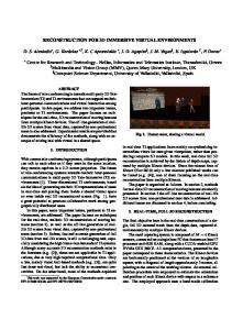
3. System Overview The immersive styling system setup basically consists of three parts: • Output device • Input devices • Software The prototype can either run in virtual reality or in augmented reality. In virtual reality a virtual table or projection wall for augmented reality video or optical seethrough glasses is used. Tracking System To track the user’s head and hand positions we use an optical tracking system from ART, which provides high accuracy and low latency. To overcome the disadvantage of keeping the camera’s line of sight clear, a redundant amount of cameras and markers is used. In addition optical tracking allows for untethered objects, such as a wireless pen. Input Devices Various tracked objects are used as input devices. They are shown in Figure 1. Glasses Depending on the setup, shutter glasses, linear polarization glasses or a head mounted display is used. The virtual images are rendered according to the user’s head position / viewpoint. Pen A wireless pen with 3 buttons is used as main input device.
SMI 2004 – Paper #86
Tangible Plane
L-Axis
3
Tape Finger
Cube-Axis
Pen
PIP-Sheet
Figure 1: Input Devices PIP-Sheet (Personal Interaction Panel) The PIP (Personal Interaction Panel) is a transparent plexiglas panel on which the application menu is projected. The menus on the panel are operated with the pen. Navigator axis (L shape, cube shape) The navigator axis is used to navigate the model in 3DOF. The user can choose between an “L”-shaped device and a cube. Tangible planes (mirror/projection) These tracked artifacts are used by the mirror and projection plane function. Both functions operate on a virtual plane, which is moved according to the artifact. Tape finger This device is only used for the virtual taping function, which is controlled by two input devices, the taping finger representing the tape-fixing finger (see below) and the pen applying a tangent to the curve.
Figure 2: Virtual Reality Setup A second scenario uses an upright projection wall to display the picture. In this case the tracked artifacts are placed on a table and the user operates the pen in front of the wall. The disadvantage of this setup is that the tracked artifacts cannot be placed anywhere conveniently.
4. Stroke input Methods 4.1. Stroke input Our approach to stroke input processing is very straight forward. While moving the 3D pen device in space the tracker continuously delivers position events. These positions are used as sample points for the stroke. The shape of the created NURBS curve depends on the distances between the sample points. The result is therefore always a trade off between complexity of the curve and the distances between sample points. Well-suited 3D curve approximation methods including algorithmic details have been described by L. Piegl and W. Tiller in [16].
Virtual Reality Setup For styling, the output device should provide high quality rendering, and immersion. We decided to use a semiimmersive virtual table with a diagonal of 1.7 meters, which allows creating e.g. parts of a car body in scale by appropriate hand gestures and arm movements. In stereoscopic mode the user wears a pair of tracked shutter glasses, and the scene is rendered according to the user’s point of view. In this way the virtual objects appear floating in space above the table. The setup is displayed in Figure 2.
Figure 3: Automatic Stroke Splitting
SMI 2004 – Paper #86
4.2. Automatic Stroke Splitting High quality curves should have as few control points as possible. But one problem with curves built of few control points is, that it is not possible for them to have sharp edges. We therefore developed a function that analyses the drawn curve according to its curvature. It detects points of high curvature and cuts the curve at these points. The resulting curve then consists of partial curves with few control points and possible sharp edges at the junctions. In Figure 3 two curves are shown. The upper curve is drawn with the conventional freehand spline function. It can clearly be seen that the curve’s tip is rounded. The lower curve is automatically split using our method, therefore the tip remains as sharp as the user drew it. The splitting algorithm uses the stroke input sample points. These sample points can be regarded as a polyline. For each point of the line the angles to neighbouring segments are calculated. If these angles are small then the curvature of the curve at this point is high. Along the list of per-point angles the maxima are searched. If an angle maxima lies above a defined curvature limit, the point becomes a splitting point. Afterwards for each segment defined by the splitting points a NURBS curve is generated according to the sample points and the distance between sample points as described in the previous section.
4.3. Stroke Oversketching In the task analysis phase we studied how stylists do their pen and paper drawings. A common technique to create a curve is to repetitively draw over – this technique is called oversketching. To mimic this curve modification method, we implemented virtual oversketching. With this function a curve can be changed by sketching a new curve over the existing one. The main tasks of the oversketching algorithm are: • Find the part of the original stroke that has been oversketched. • Substitute the oversketched part with the new stroke. • Smoothening the transition Reshaping the original stroke according to the oversketch can either be done on the base of control points or sample points.
4 the operation is performed multiple times. Although the curve itself still looks nice, surfaces created with these curves are of poor quality. Operation on sample points As opposed to the above approach, not the control points but the sample points are considered. Therefore the original curve has to be re-sampled first, because it is internally stored as NURBS curve. Then the interval of the original curve to be replaced has to be found. Therefore the closest point to the oversketched curve’s first and last point is identified. After replacing this interval, the resulting curve is converted to a NURBS curve again. Because of the recalculation of the curve’s parameters, the original curve’s character is lost. On the other hand the recalculation always creates a good quality NURBS curve that can be used to create surfaces from. Another disadvantage of this method is that the transition area at the replace interval start and end points appears to be harsher. Replacement parameters Both methods can be controlled by the user with two parameters. One parameter defines the amount of influence of the oversketched curve in the replacement interval. If the value is 1, the curve is just replaced like described before. If the value is below 1, the oversketched curve sample points or control points are calculated as to lie on a perpendicular line to the original curve’s sample point. If the scale value is 0 the curve remains unchanged. The second parameter defines a transition interval for the replacement interval end and start points. If the transition interval is zero the resulting curve might have harsh changes at the replacement interval borders. This applies even more to the method operating on sample points. Within the user defined interval the replacement therefore is done according to the above described factor of influence of the oversketched curve. Also the scaling is defined similarly. However over the transition interval scaling is a function from 0 to 1 to fade in and 1 to 0 to fade out. For better results the transition is not linear but according to a sine function.
Operation on control points In this method the oversketch stroke is first converted to a NURBS curve. In the following just the control points of the original and the oversketch curve are considered. For the oversketch curve’s first and last control point we search the corresponding control point of the original curve. Then we replace the control points in this interval with the oversketched curve’s control points. The disadvantage of this method is that the resulting control points get unequally distributed over the curve, especially if
Figure 4: Stroke Oversketching
SMI 2004 – Paper #86
5
In Figure 4 two samples of oversketching are shown. In a), the scaling parameter of the oversketched curve is 0.5. Therefore the resulting curve is about between the original and the oversketched. In b) the influence parameter is 1.0, therefore the result follows the oversketched curve. Like in most CAD applications we also provide the possibility to edit a curve by directly dragging its control points. User tests showed that designers prefer our oversketching method at early stages, where changes to apply to curves are still quite big. For posterior refinement designers still prefer control point modification, because it gives more accurate control over the result. We also extended our approach to surface oversketching, where the shape of a surface is modified according to a curve sketched close to it. (see Figure 5).
1
5 2 3
4
Figure 5: Surface Oversketching
4.4. Taping Another one-stroke curve modeling method that has been adapted from a traditional styling method is 3D tape drawing. Tape drawing is a wide-spread modeling technique in industrial design that is used to define characteristic lines, typically on 1:1 sized perspective 2-dimenisional drawings of the product model. In tape drawing instead of using pencils, a special adhesive tape is used, which the stylist unrolls with one hand (typically the right hand), sliding over the tape with the other hand applying gentle pressure to fix it on the drawing. In this way smooth 2-dimensional curves are designed, where the first hand defines the tangent line with respect to the curve point currently fixed by the other hand as illustrated in Figure 6. Experienced stylists define such taped curves with a single two-handed stroke, where the tape easily allows undoing or correcting the curve by un-taping it back to any point of the curve, as required. A first approach to develop a computer aided 2D tape drawing has been presented by T. Grossman et al. [17],
Figure 6: Traditional 2D-tape drawing allowing to define a curve by using a 2D device (mouse) and defining two subsequently clicked points on the projection plane as a pair being the first point, a point on the curve and the second point defining a tangent line (the vector between the two points). To define the final 2D curve, the curve points are interpolated applying a Hermite interpolation using the tangent (direction and value of the first derivative) information as boundary conditions. The approach presented in this paper differs from previous approaches, and actually extends digital tape drawing in four aspects: 1. It maps the 2-dimensional tape drawing into a corresponding 3D metaphor as has been introduced by De Amicis et al. [18]; 2. It extends 2D tape drawing to a 3D curve modeling method, enhancing the modeling power of this styling technique; 3. It provides direct manipulative two-handed input with 3D devices, which naturally builds on existing well developed skills of stylists, allowing to define 3D curves in a single stroke as it is the case in the traditional 2D case; 4. Finally, the approach integrates tape drawing into synthetically generated immersive environments, allowing stylists to immediately inspect and validate resulting curves from any viewpoint, with any scaling factor, and related to the 3-dimensional presentation of the product model, instead of a perspective 2D drawing, only. The 3D devices applied for 3D tape drawing are shown in Figure 7 and Figure 1. Those devices are a “tape finger” device (left hand), which is tracked for the position of the hand and finger, respectively, defining the curve points, and a pen device (right hand) corresponding to the roll of tape. The curve modeling starts when pushing the pen button and stops when releasing it. All optically tracked positions of these two devices are used to define the final shape of the curve. In addition the head position and view orientation of the user as well as the “navigator axis” are tracked to define the current view with respect to the model.
SMI 2004 – Paper #86
6 2. Finger displacements in depth are corrected avoiding unwanted oscillations in that direction. Remember that stylists have a physical feedback constraining the finger movement to a given plane when taping on drawings, which they do not have in virtual space; 3. The orientation, which in contrast to 2D tape drawing is now a 3D vector, is defined by the leading pen (taking the place of the tape roll) exactly as it is the case of the original tape drawing process. Hence it provides a means of adding degrees of freedom to tape drawing, benefiting from the already well developed skills of stylists. Once the input is finalized the sample points Pi are approximated by a cubic NURBS curve. Ideas to extend the 3D tape drawing metaphor to an approach for freeform surface modeling, i.e. working with a tangent plane instead of a tangent line, have been rejected, because it turned out that the power of such an approach would be limited to the type of surfaces that can better be modeled as linearly extruded 3D curves.
Figure 7: Virtual 3D tape drawing at the Virtual Table with the optically tracked finger (left hand), pen (right hand), head position, pip position, an the “navigator axis” (on the right). When starting the 3D tape drawing, the method is initialized with the current position of the finger Pf1, which also defines the starting point P1 of the curve, and the current position of the pen Pp1. New positions of the finger or the pen are considered, if their current positions have a minimal displacement with respect to their last position. A threshold of 10-5 to 10-4 units displacement has proven to provide an accuracy well accepted by users at user tests. For the iterative definition of the sample points Pi of the curve the following approach has shown to work well in practice: Given the last point Pi two vectors are defined, the relative displacement of the finger PiPfi + 1 and the vector defined by PiPpi + 1 . Now the current finger position is projected onto the
trajectory of PiPpi + 1 (see Figure 1 for details). The procedure has the following characteristics: 1. Any subsequent point is defined such that the vector between the new Pi+1 and the pen position defines a tangent line on this point Pi+1, as it is the case in the traditional 2D tape drawing;
Figure 8: Calculation of the taped 3D curve with points Pi derived from the current and last finger and pen positions.
4.5. Strokes as gestures for input control The immersive modeller currently supports two functions via gesture input. The gesture is performed using a 3rd pen button. Drawing a circle over a surface will delete the surface. Drawing a rectangle over a surface will select it (see Figure 9). The gesture interface is implemented in a way, that it can easily be expanded to support further functions. After further user evaluation we shall decide which other functions will be supported. For gesture recognition CALI [19] was integrated into the prototype. The 3D input is projected onto a regression plane, mapped to 2D and sent to CALI, which returns the recognised gesture.
SMI 2004 – Paper #86
7
5. Immersive Constraints 5.1. Tangible planes
delete
select
Figure 9: Stroke gestures to delete and select surfaces.
Our immersive modeler has two drawing tools based on planes, namely a mirror plane and a projection plane. With an active mirror plane, all user interaction is mirrored according to the position of the mirror plane. The purpose of the projection plane is to constrain the user input to an arbitrary positioned plane. To handle these planes we make use of the immersive environment and the tracking system. The virtual planes have a physical counterpart, the tangible plane (see Figure 1). Because of their transparent Plexiglas they merge seamlessly with the virtual rederings in immersive space. We attached marker balls to the plane, so it is tracked by the tracking system. The user can now use these physical objects to position the virtual planes in immersive space. The virtual plane is projected on the Plexiglas.
5.2. Projection plane to table Stylists are used to work with media that returns haptic feedback. In free space no feedback is available, which makes accurate drawing a difficult task. Haptic devices might be a promising solution, but are not conveniently available for an area as large as the virtual table we use. We found a solution to overcome this problem at least for drawing on 2D planes by using the table itself as a drawing surface. By using the tangible plane, we arbitrarily position a projection plane somewhere inside the scene. When activating the “projection-plane-to-table”-function, the projection plane is rotated to the table surface, so the designer can directly draw on the table surface. Furthermore all geometry on the top of the table is clipped away. On the upper part of Figure 10 the projection plane is positioned somewhere in the scene. On the lower part the rotated view clipped at the plane position in orthographic view mode can be seen.
Rotate plane on table surface
Figure 10: The stylist positions a plane arbitrarily in the immersive space. Then the scene is rotated, so that the plane is equivalent to the table (work bench) surface.
5.3. Constraint stroke manipulation To manipulate a stroke in our immersive modeller we provide the already described oversketching and control point modification. A problem with modelling in free space is, that effects of oversketching in direction of the user’s view vector cannot be controlled intuitively. We therefore added the option, that when manipulating a stroke, changes in this direction are suppressed. For simplification the suppressed direction is one of the dimensions of the coordinate system. For this purpose the axis most parallel to the user view vector is calculated. If then the stylist moves a control point, the parameters affecting the suppressed axis are not changed.
SMI 2004 – Paper #86
6. User Tests and Results With our immersive modeler we enter a new domain in CAS. The quality of the results we can expect from our system is not yet comparable to commercial software used in this field nowadays. We do not compete with them in the sense of precision and surface quality. Our goal is to create models comparable to quick paper sketches, giving the stylist a tool to create a 3D model and to express his design ideas as fast as he would do with pen and paper. Therefore our user tests did not compare our system to software used in the styling phase today, but questioned, if immersive modeling had the potential to serve as an additional tool to reach our goal of quick sketches. The main user testing has been done in multiple sessions with car stylists from major automobile manufactors and auto styling companies. Apart from this we also made some minor testing with product designers and media artists. In the first round of user testing with an earlier prototype each user had about two hours, starting with a tutorial and a free sketch phase at the end. All users had computer background knowledge, some working with CAS tools, others with paint tools. At this time we tested 20 persons to get a more general feedback. The second user test was done with our latest prototype and included only 3 stylists, each of them having two days time to test the system and discuss their views. In general it can be said that in principle all users accepted the system, although everybody could imagine an immersive workplace only as part time addition to its usual working environment. More than two hours in a row did not appear to be convenient due to the working stance and the stereo display. For more detailed comments it is necessary to distinguish between the different backgrounds of the users: • Junior Car Stylists A group of people already used to CAS due to their education. They tend to accept the immersive environment pretty fast. But, because of their background in CAS software, they demand for similar handling, functions and precision, as they are used to. Though the 3D environment is well liked for immediate result review they prefer 2D views and planes for the construction phase. Strokes are preferably drawn on a plane and not in free space. • Senior Car Stylists Educated with pen and paper and using a computer mainly with paint software, they have a different approach in using the software. 2D modes and planes seem to them even more important than to the juniors, additionally they get irritated by head tracking. Another drawback to them was the fact, that calibration of 3D devices is not as precise as the physical counterparts. The fact that the virtual pen and the physical pen device are never perfectly aligned irritated them.
8 • Media and Fine Artists Though actually media and fine artists are a very different group, they have in common that they are not as limited to 2D planes as the car stylists. Fine artists are practised to draw on canvas with rather free and wide arm movements whereas media artist often do not come with special drawing customs. Their impression was that though they have difficulties to make drawings in free space right now, after a training period working with 3D strokes should be possible and usable.
Figure 11: Results the immersive modeler. The surfaces were created from curves. Altogether all users have already been able to create 3D sketches expressing their intended design. Figure 11 shows two cars created with the modeller in just two to five minutes. All surfaces were created from curves using the described stroke input. Though surface connection and detailed modelling is still not supported efficiently, the stylists were able to create models that represent the character and idea of the intended design in a short amount of time.
SMI 2004 – Paper #86
7. Conclusion and Future Work The results show our immersive modeler already enables stylists to sketch characteristic 3D models within a short time. But to be able to model in more detail and for improved interaction a lot of work is still to be done. Stroke input has to be improved by giving users more influence on how the input sample points are converted to NURBS curves. Having control over the complexity of the curve is important for high quality results. Furthermore we work on integrating features to easily trim parts of the curve, as well as a more controlled oversketching, where the user can exactly define the starting point from where the curve should be modified. Furthermore the functions to create surfaces from strokes have to be improved and extended. Finally surfaces should be connectable without gaps and modifications and changes of a surface should affect connected surfaces accordingly.
Acknowledgement This work was funded in part by the European Commission Grant #IST-2000-28169 (SmartSketches project).
References [1]
J.Butterworth, A. Davidson, S. Hench, T.M. Olano. 3DM: A Three Dimensional Modeler Using a Head-Mounted Display. Communications of the ACM, 55-62, June 1992
[2]
A., Steed, M., Slater, 3D interactions with the desktop bat. , Computer Graphics Forum,14(2), 97-104,Blackwell, 1995.
[3]
C.-C. P. Chu, T. H. Dani, and T. Gadh: Multi-sensory user-interface for a virtual-reality-based Computer aided design system, Computer-Aided Design, Vol. 29, No. 10, pp. 709-725, 1997.
[4]
A.Forsberg, J. LaViola, L. Markosian, R. Zeleznik. Seamless Interaction in Virtual Reality. IEEE Computer Graphics & Applications, 17(6):6-9, 1997
[5]
B. Fröhlich, and M. Fischer: Erstellen von Produktionsmodellen und Produktionsplanung auf der Responsive Workbench. Wirtschaftsfaktor Virtual Reality: Planen, Bauen und Marketing mit VR, Congress 98, ARCiTEC, Graz, Austria, March 5-6, 1998, CD-ROM Proceedings, www-graphics.stanford.edu/projects/RWB/newindex.html
[6]
M.Usoh, M. Slater, T. Vassilev. Collaborative geometrical modeling in immersive virtual environments. Eurographics Workshop, 1995
[7]
C.Hummels, C. Overbeeke, P.J. Stappers, T. Kehler. Exploiting the Expressive: Rapid Entry of Car Designer’s Conceptual Sketches into a CAD Enviroment. Conference Proceedings of the 28th International Symposium on Automotive Technology and Automation (ISATA '97)
[8]
C.Hummels, A. Paalder, C. Overbeeke, P.J. Stappers, G. Smets. TwoHanded Gesture-Based Car Styling in a Virtual Environment. Conference Proceedings of the 28th International Symposium on Automotive Technology and Automation (ISATA '97)
[9]
M.Fontana, F. Giannini, M. Meirana, A Free-form Feature Taxonomy, Eurographics '99, 18(3), 1999
[10] T.H. Dani, R. Gadh. COVIRDS: A Conceptual Virtual Design System. Computer Aided Design, Vol. 29(8): 555-563, 1997
9 [11] T.H. Dani, L. Wang, R. Gadh. Free-Form Surface Design in a Virtual Enviroment. Proc. of ASME '99 Design Engineering Technical Conferences, ASME 1999 [12] Liverani, A. and Piraccini, G. 2002. Full Scale Surface Modeling in Virtual Reality. In Proceedings of 12th International Conference on Design Tools and Methods in Industrial Engineering, Rimini – Italy, September 5-7 2002 [13] G.Wesche, H.-P. Seidel. FreeDrawer – A Free-Form Sketching System on the Responsive Workbench. VRST 2001 Proc., Alberta, Canada, November 2001. [14] G.Wesche, M. Droske. Conceptual Free-Form Styling on the Responsive Workbench. VRST 2000, Proc., Seoul, Korea, 2000. [15] M. Fiorentino, R. De Amicis, A. Stork, G. Monno, “Spacedesign: A Mixed Reality Workspace for Aesthetic Industrial Design”, Proceedings of ISMAR 2002 IEEE and ACM International Symposium on Mixed and Augmented Reality, Darmstadt, Germany, Sept. 30 - Oct. 1, 2002. [16] L. Piegl, W. Tiller, „The NURBS Book“, ISBN-3-540-55069-0, Springer, 1995, pp. 405-453. [17] T. Grossman, R. Balakrishnan, G. Kurtenbach, G. Fitzmaurice, A. Khan, B. Buxton., “Creating Principal 3D Curves with Digital Tape Drawing”, In CHI 2002, Minneapolis, Minnesota, USA, April 20-25, 2002. [18] R. De Amicis, M. Fiorentino, A. Stork, G. Monno, “3D-Tape Drawing in Virtual and Augmented Reality”, Proceedings of the XIII ADM International Conference on Tools and Methods Evolution in Engineering Design, 4-6 June, Napoli, 2003. [19] Fonseca, M., Pimentel C., Jorge J., “CALI: An Online Scribble Recognizer for Calligraphic Interfaces”, Proceedings of the 2002 AAAI Spring Symposium - Sketch Understanding, pages 51-58, Palo Alto, USA, Mar 2002


![Barber Styling - RochesterWorks! [PDF]](https://m.moam.info/img/260x300/barber-styling-rochesterworks-pdf_6499a844098a9e442f8b4606.jpg)