Available online at www.sciencedirect.com
Procedia Engineering 51 (2013) 141 – 150
Non-Circuit Branches of the 3rd Nirma University International Conference on Engineering (NUiCONE 2012)
Structural Engineering Challenges in Structures for Cooling Water System in Thermal Power Plant Dipal P Trivedia, Raja I Baggaa, Jignesh V Chokshia,* a
L&T-Sargent & Lundy Limited, L&T Knowledge City,SEZ Unit NH-8, Ajwa-Waghodia Crossing, Vadodara – 390019, Gujarat., INDIA
Abstract Water is one of the most important resource requirements in thermal power plant for process cooling in the condenser, ash disposal, cooling of plant auxiliaries and various other plant consumptive uses. Cooling water requirement in a thermal power plant is a major water resource issue for project feasibility as it has tremendous effect on the surrounding environment, population, animal and aquatic life. In a thermal power plant, Cooling Water system is one of the most important power plant systems which ensure continuous supply of cooling water for steam condensation in condenser and other plant equipment. Power plants are key elements of national infrastructure and eco-friendly solutions are required for commitment to the society. With a thrust on use of non-agricultural land as well as potential for importing coal through sea, the power plants are now being developed along the coastal lines, where water is available in abundance. The cooling process can be done either through air or with use of water and both have its merits and demerits. With increased power demand, the sizes of power plant units have increased substantially as compared with previous decades. This has further called for large structures and has imposed many engineering challenges for a power plant engineer. From civil and structural engineering perspective, the CW system involves very large water conveying and retaining structures namely cooling towers, intake and discharge channels, forebay, large underground sump, pump station for housing of large cooling water pumps, large piping between cooling tower and condenser, etc. In order to reduce the capital and running cost of the plant, thrust on economical design is emphasized. This imposes an additional constraint for engineer and it demands meticulous analysis and design to provide optimum techno-commercial solution. The present study describes various types of CW systems, structures and associated engineering challenges faced by structural engineer.
© 2012 2013 The Authors.byPublished Elsevier Ltd. and/or peer-review under responsibility of the Institute of Technology Nirma Published Elsevierby Ltd. Selection Selection andAhmedabad. peer-review under responsibility of Institute of Technology, Nirma University, Ahmedabad. University, Keywords: CW, CW System, Cooling Water, Challenges, System.
Nomenclature CW ESP FEM FRP GRP HRSG IDCT NDCT RC
Cooling Water Electrostatic Precipitator Finite Element Method Fibre Reinforced Plastic Glass Reinforced Plastic Heat Recovery Steam Generator Induced Draft Cooling Tower Natural Draft Cooling Tower Reinforced Concrete
* Dipal P Trivedi Tel.: +91-265-245-6240; fax: +91-265-245-6300, E-mail address:
[email protected], Web: www.lntsnl.com
1877-7058 © 2013 The Authors. Published by Elsevier Ltd. Selection and peer-review under responsibility of Institute of Technology, Nirma University, Ahmedabad. doi:10.1016/j.proeng.2013.01.021
142
Dipal P Trivedi et. al / Procedia Engineering 51 (2013) 141 – 150
1. Introduction to Cooling Water System In a typical thermal power plant, power is generated through steam turbine generator. The thermal energy of high pressure steam is converted in to mechanical energy in the steam turbine where in steam is supplied to turbine blades and as a result rotor is rotates at high speed. The turbine rotor is connected with generator rotor and hence rotation of turbine rotor results in rotation of generator rotor. Ultimately power is generated in the generator due to rotation of rotor against static components of generator. In power plant, fuel is burned to generate high pressure steam. The steam, exhausted from turbine is condensed in condenser. For condensation of steam, either air or water is supplied through the condenser so as to exchange heat from steam. The cooling water system ensures continuous flow of water or air through condenser for steam condensation. The general classification of types of cooling system is furnished in fig 1. After condensation, the steam is condensed back to liquid (i.e. water). In case of water cooled system, the water which comes out from condenser is comparatively hot. This hot water is supplied back to cooling tower where the heat is extracted and water is cooled again for recirculating to condenser again. See fig 2 for schematic representation of a typical power plant system including cooling water system. 1.
Cooling water
2.
CW Pump
3.
Cooling tower
4.
CW Pipe
5.
Condenser
6.
Steam Turbine
7.
Boiler/HRSG
Generator 8.
ESP
9.
Chimney
10. Ash system 11. Coal system
Fig 1 Types of cooling system
Fig 2 Typical Power Plant Schematic with CW system
The function of cooling water system is to circulate cooling water through condenser by pumping. Hence, a typical CW system includes structures like cooling towers, underground channels, sump & pump station, CW piping. Cooling water is taken from a body of water such as a river, lake or ocean. 1.1. Open Cooling System In open or once through CW system, cooling water is drawn from the source water body (sea/river/pond etc.) through underground CW Channel, CW forebay and collected in CW sump below CW pump station. From here the water is pumped to condenser through CW pipes. The hot water from condenser outlet is ultimately discharged to source water body through underground RC box culvert and channel. The heat is gradually transferred to the atmosphere by evaporation, convection and radiation. It shall be noted here that there is no cooling tower required in this system and also water is not re-circulated and hence this system is called as open cooling system. This system is most appropriate for power plants located near to the water body having large volume of water, generally near sea. 1.2. Closed Cooling System (Water cooling) In closed cooling system, the hot water from condenser discharge is diverted to cooling tower basin through CW return pipe. In the cooling tower heat is dissipated to atmosphere and cold water is stored in cold water basin. The cold water is circulated by gravity flow from cooling tower basin to CW sump through CW channel and forebay. From Sump, water is collected in CW sump and pumped back to condenser through CW supply pipes. Thus in a closed cooling system, the circulating water serves as an intermediate heat transfer medium from which the waste heat is directly rejected to the atmosphere. Cooling towers have been used at power plants where large volume of water is not available. There are generally two types of cooling towers, Natural Draught Cooling Tower (NDCT) and Induced Draft Cooling Tower (IDCT). In case of NDCT, no mechanical device is utilized to create air flow through the tower and the air flow is derived from
Dipal P Trivedi et. al / Procedia Engineering 51 (2013) 141 – 150
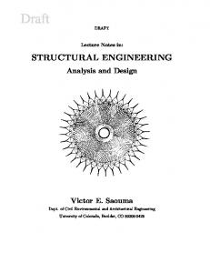
natural induction. An IDCT is provided with top-mounted fans that induce atmospheric air to flow up through the tower, as warm water falls downward. However, IDCT consumes additional power leading to reduction in net power production. See fig 3 showing typical view of entire CW system of a power plant.
Fig 3 3D view of CW System 1.3. Closed Cooling System (Air cooling) Air cooled systems are provided where the water is scarce and it is not affordable to provide water for cooling purpose. The cooling is done through air cooled condenser which requires high amount of electrical power and thus it reduces the net power production. Moreover, a power plant with air cooled condenser requires huge chiller plants for cooling of air and therefore results in high capital investment in acquiring land for setting up chiller plants. Though environment friendly, Air cooled condenser (ACC) has high operating cost and less net power production as compared to water cooled systems. A detailed economic analysis is performed to determine the optimum balance between power cycle efficiency and circulating water system capital expenditures & operating costs. This is done during the power plant conceptual design phase which generally involves a lot of thermodynamics. The present study focuses on structural engineering challenges in CW system structures/facilities for a typical thermal power plant. Air cooled system is excluded from the scope of present study. The engineering challenges for cooling tower structures are quite challenging, however, the same is also excluded from the scope of present study. 2. CW system structures A typical 600 to 700MW Coal fired power plant with CW system requires continuous water flow up to 80,000 m3/hr (i.e. 800 lac liters/hr, which is significantly high water flow). Hence, CW pumps with capacity ranging from 30,000 m3/hr to 40,000 m3/hr are generally installed. To handle large water volume, relevant CW system structures are also very large. Engineering, design and construction of CW structures is a major activity in any power plant. Many times 10 to 15% of the total concrete volume of a power plant is consumed in a CW system structures only. The CW system also falls on critical path of a project and hence it is extremely important system for project. The CW system includes varieties of water retaining structures like deep underground RC channels, RC forebay (channel having slopes and flare), deep underground RC sump having depth ranging from 7 to 14 meter deep below ground, large diameter (up to 4.0m diameter) underground CW pipe with concrete encasement, culverts, thrust blocks, CW pit inside, underground CW discharge RC box culvert (with pressurized flow), underground CW discharge channel, etc. 3. Challenges in CW System Structures CW system structures are large underground water retaining structures having unique shape, size and loads. The analysis and design of such structures is challenging. Stability against buoyancy due to presence of ground water table for structure with large widths. Analysis and design of CW system structures at initial stages with limited input data and later accommodate major changes upon maturity of input data, especially due to fact that CW system is always on critical path.
143
144
Dipal P Trivedi et. al / Procedia Engineering 51 (2013) 141 – 150
Use of high grade of concrete, reinforcement steel for CW system structures exposed to water and other environmental conditions like temperature etc. Provision of joints in water retaining structures and addressing construction notes to ensure smooth construction is very important aspect. Provisions for leak proof construction and protection of concrete and reinforcement against water. Providing accurate details of complex and unique structural components for ease of construction. To form entire system in 3D model and checking interface is a distinctive challenge to a structural engineering. Sharing of these models with site increases construction / erection productivity and reduces site queries, avoiding rework due to physical clashes Providing most optimum and cost effective design. Structural engineering challenges for each CW system structures are covered in subsequent sections. 3.1. CW Channel Cooling water required in power plant is drawn from cooling tower or source water body through underground CW channels. The width of channel generally ranges from 2m to 18m and depth ranges from 3m to 5m below ground. The length of channel varies from 200m to 1000m. In presence of ground water table, the structural design size of CW channel is governed in stability against uplift force due to ground water table. Considering the possibility that channel may be empty for maintenance etc., dead load of internal water pressure also not considered for stability. Under such conditions sometimes it is required to provide channel raft thickness up to 2m. See Fig 4 for a typical cross section of a CW channel.
Fig 4 Typical cross sectional detail of CW channel To increase dead weight against uplift force, bottom slab may be provided with projections. However, when channel is extremely wide compared to depth (e.g. 4.0m deep and 18.0m wide). In such case, design thickness may govern in bending moment at mid span of bottom slab. Increased projection does not ensure no uplift at center of channel. Sometimes pressure relief valves (PRV) are used to release the uplift pressure by allowing the ground water table to enter inside channel. Reduction in uplift pressure means less concrete weight required for stability against uplift. As a result, design thickness of bottom slab of channel also gets reduced by using PRV and thus save huge concrete material and construction cost. Many times use of PRV is not allowed like for sea water where saline water and marine agents may choke the PRV. It is practically not possible to repair choked PRV. Choking of PRV may happen due to other reasons like impurities in ground water or soil below channel bottom slab. Hence, provision of PRV requires great care. Due to huge length of channel, provision of construction, expansion and contraction joints at desired locations require great attention. 3.2. CW Forebay The water flows into the underground CW forebay from CW Channel by gravity. The forebay is typically an underground channel which is trapezoidal in plan with small width at inlet and large width at other end near CW sump. The
Dipal P Trivedi et. al / Procedia Engineering 51 (2013) 141 – 150
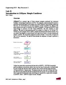
bottom slab of forebay is uniformly sloping with shallow level at inlet channel end and deeper level at sump end. In other words, the shape of forebay is cut tetrahedron. This shape is required to expand the flow of water from very small width of CW Channel to large width at CW Sump to ensure proper flow control without any turbulence. The screenshot in Fig 5 shows a 3-Dimensional model of CW forebay, CW sump and pump station.
Fig 5 3D model for CW forebay, CW sump and CW pump station Since the forebay dimensions vary in plan as well as in elevation, the design lateral earth pressure, uplift ground water pressure and internal water pressure also vary across the entire forebay. Hence, it is challenging to analyze and design the forebay. A detailed 3D model is prepared for analysis, which may require more engineering effort. Alternatively, relatively quick engineering approach may be adopted where in forebay may be divided in segments and each segment shall be analyzed and designed separately. It is challenging to select the analysis and design approach based on project specific schedule. Due to typical tetrahedron like shape, the center of gravity of a forebay structure is located on deeper side of forebay and hence the equilibrium check of forebay is also unique task. The CW forebay is generally modeled in FEM based analysis software like SAP2000 [3] or SAFE [4] due to its geometric non uniformity and complex behavior under different loading conditions. Fig 6 (a), (b) screenshot depicts a CW Forebay FEM analysis model and a 3D model for a typical power plant.
Fig 6 (a) CW Forebay FEM Analysis Model View
Fig 6 (b) CW Forebay 3D Model View
For forebay with depth greater than 7m below ground subjected to lateral earth pressure and surcharge load of 2T/m2, forebay wall shall be supported by counterfort walls. Due to varying geometry of forebay, design of vertical wall with counterfort is an additional challenge. Selection of spacing and size of counterforts shall be critically done ensure optimum design and construction ease. The counterfort walls can be 1m x 4m size for a 14m deep counterfort wall. Reinforcement on one side of counterfort may be as large as 4 layers of 32mm diameter bars with 9 bars per layer to take large earth pressure due to saturated soil and surcharge. Fig 7 (a), (b), (c) furnishes typical details of counterfort.
145
146
Dipal P Trivedi et. al / Procedia Engineering 51 (2013) 141 – 150
Fig 7 (a) Counterfort Wall Reinforcement detail
Fig 7 (b) Counterfort Wall Reinforcement section
Fig 7 (c) CW forebay with Counterfort Walls
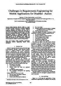
Similar to CW channel, for CW forebay also, design against uplift force due to ground water table is critical due to fact that as compared to the channel, forebay always has more width and depth. Use of PRV or other means of reducing uplift pressure becomes unavoidable for economical design. See Fig 8 for a typical detail of PRV. 3.3. CW Sump The water from the CW Forebay flows in to the CW Sump. The CW sump is divided in to compartments with one CW pump on top of each compartment. Water collected in sump is pumped in to the CW pump through suction pipe suspended from bottom of pump. By virtue of arrangement, the CW sump is having peripheral walls and internal partition walls supported on a common base raft. Also, at the top of walls the entire sump area is covered with slab. For a typical 600MW and above power plant, a CW Sump may have plan size ranging from 20m to 70m. The depth may be 7m to 14m deep below ground. Fig 9 (a), (b) shows 3-Dimensional model of a CW pumping station)
Fig 9 (a) 3D model of CW Forebay and pump station
Fig 9 (b) 3D sectional view of CW sump & pump station
Fig 8 Typical sectional detail of Pressure Relief Valve (PRV) in base slab
Similar to Forebay walls, all peripheral walls of CW sump may be provided with counterfort walls to retain earth pressure. It is always challenging to consider counterfort walls because the arrangement and size of counterfort walls must be judiciously arrived at to ensure most optimum design solution and ease of construction. Internal walls (between two adjacent compartments) are propped cantilever wall fixed at base and pinned at top. Thickness of these walls may range from 0.6m to 1.2m. For center to center spacing of two adjacent pumps, deciding the thickness of this wall is must at early stage when the overall general arrangement of CW sump is prepared. Once the arrangement is finalized, then later on, there is no opportunity available for changing the wall thickness. Because change
Dipal P Trivedi et. al / Procedia Engineering 51 (2013) 141 – 150
in wall thickness results in sump volume change which is not acceptable from flow stability point of view. Hence, it is necessary to finalize thickness of wall. A detailed analysis and design of entire CW Sump structure including walls, top slab and base raft is complex task. Either detailed 3D analysis model of entire sump shall be prepared, which is extremely difficult and time consuming task or else the structural elements may be analyzed and designed separately. It is important to select appropriate approach based on engineering time, design optimization and construction schedule requirement. Fig 10 screenshot shows SAFE[4] model for CW sump base mat.
Fig 10 FEM analysis model of CW sump base raft
Fig 11 Sectional plan detail of wall with slots for stop log gate –Typical Drawing Detail
There exists number of equipment (for water flow control, filter and other purpose) like stop log gates, bar screen, trash rack, travelling band screen, etc. in CW sump, which require slots in walls and base raft. Since the input for such slots is not available at initial stages when civil design is done, it is required to consider provision for such slots by means of providing secondary stage concrete and dowel bars. See Fig 11 for detail of slots in concrete for stop log gates. The design of CW sump top slab is governed due to CW pump supported on this slab. CW pump weigh as high as 150 ton. Also, large openings are also required in slab for suction pipe. Analysis and design of such floor slab subjected to heavy rotating pump loads with large openings is challenging. Many times in addition of static loads, dynamic loads are also provided by pump supplier. Performing dynamic analysis is additional challenge. The design thickness of slab may be as high as 1200mm thick in many cases. Fig 12 (a), (b) SAFE [4] model for CW pump supporting floor.
Fig 12 (a) FEM analysis model for CW Pump supporting floor slab with circular opening
Fig 12 (b) FEM analysis model for CW Pump supporting floor slab with rectangular opening
Sometimes pump with concrete volute type suction is provided instead of suction pipe. Volute type pump suction ensures better performance efficiency as compared to conventional suction pipe with bell mouth. However, the structural design and construction of concrete volute is complex and complicated activity. Refer fig 13 (a), (b), (c) for details of concrete volute type sump and pump station.
147
148
Dipal P Trivedi et. al / Procedia Engineering 51 (2013) 141 – 150
Fig 13 (a) Concrete Volute Plan
Fig 13 (b) Concrete Volute Section
Fig 13 (c) Concrete Volute Construction stage picture
In a CW system when water flow through different types of sections of channel, forebay and sump and also the flow are diverted by virtue of arrangement of structures, there are chances of generation of turbulence in water. This may result in unfavorable conditions at pump suction which can ultimately affect the pumping efficiency. It shall be noted that bottom of suction pipe is bell mouth shape with diameter as large as 2.5m to 4m. Hence, for identifying any potential turbulence, detailed flow model studies are performed on prototype models of channels, forebay, sump and pump by expert agency. Based on flow model study, suitable flow smoothening devices may be provided. By means of providing flow smoothening devices, it is possible to ensure favorable flow conditions at the pump inlet. Few of the common flow smoothening devices are divide walls, curtain walls in sump, splitter below pump suction bell mouth, fillers at corner locations (wall to wall, wall to base raft) around pump suction bell, etc. See fig 14 (a), (b) containing arrangement of flow CW pump suction bell mouth and smoothening devices.
Fig 14 (a) 3D model view of CW sump with curtain, splitter below pump bell.
Fig 14 (b) Splitter, Filler at pump suction during flow model study
Many times the flow model study is conducted during the later stages of the project whereas civil detail drawings are released in initial stage. In absence of exact arrangement of flow smoothening devices, provision is kept in civil design by means of providing dowel bars based on best engineering judgment. Construction of major structure is done at site and later provision of dowel bars will enable construction of flow smoothening devices when the relevant data is available. Sometimes the details of flow smoothening devices are difficult to understand by site engineer with 2D detailing, therefore 3D isometric views are also furnished on the civil detail drawing in addition to 2D details. See Fig 15 (a), (b) for arrangement of fillets and splitter in CW sump.
Fig 15 (a) Plan view for arrangement of flow smoothening filler and splitter in CW Sump
Fig 15 (b) Isometric view for arrangement of flow smoothening filler and splitter in CW Sump
Dipal P Trivedi et. al / Procedia Engineering 51 (2013) 141 – 150
For CW sump where mass concreting is unavoidable, providing arrangement and details of construction and expansion joints in concrete is an additional challenge. Special notes pertaining to construction sequence, excavation, backfilling and stability of existing adjacent underground structures, protection of concrete by means of anticorrosive painting, etc. are added in the design drawings. It is very much important to envisage and add such notes in design drawing. 3.4. CW Piping The water pumped out from CW Pumps is supplied to condenser through CW supply pipes. In case of closed CW system, hot water coming out from condenser is also diverted towards cooling tower through CW return pipes. Both CW supply and return pipe is buried below ground. Since CW Pipes are buried below ground major concrete foundations are not required. Since diameter of CW pipe is up to 4.0m (almost double the height of an average man) the providing construction sequence is very critical. Due to length, differential settlement of soil below pipe may result in additional stresses especially when CW pipes are FRP/GRP type of material. Differential settlement is possible at junction of pipe with CW pit and sump wall also. It is challenging to anticipate and provide provisions for avoiding differential settlement. See Fig 16 (a) and (b) for CW pipe.
Fig 16 (a) CW Pipe below ground
Fig 16 (b) CW Pipe below ground with concrete encasement At CW pipe bend locations large RC thrust blocks are required due to thrust force from flow of high pressure water in pipe. Also, at road rail crossings, RC encasement of pipe is required for protection against moving loads. Engineering of thrust block and encasement are unique. 3.5. CW Pit CW Pit is underground RC pit inside turbine building in front of condenser. CW supply and return pipe from condenser is housed in this pit. The CW pipes and relevant accessories like filter, valve, etc. and other equipment are arranged in CW pit. Also turbine building structural columns and side walls of pit are located in the same pit due to compact arrangement of these facilities. Analysis and design of such a compactly arranged pit subjected to loads from earth retaining side walls, turbine building columns, CW pipes and accessories and other equipment is very complex. See Fig 17 (a) for 3D model of CW Pit.
Fig 17 (a) 3D model of CW Pit
Fig 17 (b) FEM analysis model of CW Pit in SAP2000 [3]
149
150
Dipal P Trivedi et. al / Procedia Engineering 51 (2013) 141 – 150
CW pipe enter in CW pit through large openings (2.0 to 3.0m diameter) in CW pit wall. The analysis and design of such CW Pit retaining wall having large openings subjected to lateral earth pressure is critical. Use of FEM software is unavoidable for accurate analysis and design of such wall. See fig 17 (b) for FEM analysis model of CW Pit. Since, many different facilities are arranged inside CW pit within limited space, it is challenging to ensure structural design is free from interface with other facilities. The CW pit is located just adjacent to foundation for steam turbine generator, which is subjected to vibrations from turbine generator machine. Deciding founding level of CW pit and ensuring proper isolation from turbine generator foundation needs accurate assessment of the underground facilities. 3.6. CW Discharge Culvert In case of open (once through) CW system, the hot water from condenser outlet is discharged in to underground RC box discharge culvert at high pressure and temperature. Due to thermal cycle requirements, the RC culverts are subjected to pressurized flow to the tune of 200kN/m2 and also subjected to earth pressure on all sides from outside. For a ground supported box structure subjected to loads from all inside surface and outside surface is challenging because it is difficult to establish the boundary conditions in analysis model. To solve the problem; concept of symmetry shall be used. In this situation, the top slab is analyzed by considering full horizontal span and half the height of walls. Necessary boundary conditions are applied to simulate the structural behavior. Similarly, the vertical walls are analyzed. See fig 18 (a) for typical detail of CW culvert. See fig 18 (b), (c) for analysis in SAP2000 [3] using concept of symmetry.
Fig 18 (a)
Fig 18 (b)
Fig 18 (c)
Summary CW system is an important and critical system of any thermal power plant and involves various complex structures subjected to large magnitude of forces. Engineering and design of these structures is highly challenging to ascertain correct estimation of loading conditions, behavior under various loading types, need for meticulous analysis, interface management with various engineering disciplines, accurate geotechnical consideration, economical design and detailing to ensure ease of construction and serve the purpose during lifetime of a power plant. The structural engineer needs to apply wisdom and intuition in many cases to solve complexity associated with structures of CW system. Acknowledgements Authors are thankful to M/s. L&T-Sargent & Lundy Limited, Vadodara, Gujarat, India for their support for this work. References [1] Black & Veatch, 1996. Power Plant Engineering, Springer Science+Business Media, Inc., 233 Spring Street, New York, NY 10013, USA. [2] Report on Minimisation of Water Requirement in Coal Based Thermal Power Stations: Central Electricity Authority, New Delhi. Jan. 2012. [3] Computers and Structures, Inc., “Structural Analysis Program, Version 11.08”, User Manual, Berkeley, California. [4] Computers and Structures, Inc., “Slab Analysis by the Finite Element Method, Version 12.2.0”, User Manual, Berkeley, California. [5] Hydraulic Institute Standard 9.8 1998.”Pump Intake Design”.