Research Article
Structural optimization of reinforced concrete spatial structures with different structural openings and forms Agim Seranaj*1, Erald Elezi2, Altin Seranaj2 1Department 2Department
Albania
of Structural Mechanics, Polytechnic University of Tirana, Albania of Building Constructions and Transport Infrastructure, Polytechnic University of Tirana,
Article Info
Abstract
Article history: Received 26 July 2016 Revised 23 Jan 2017 Accepted 07 Feb 2017 Keywords: Spatial structures, Optimization, Finite Element Method, Static
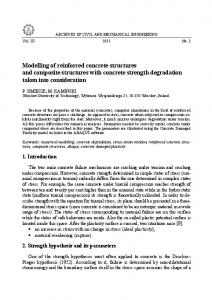
The first reinforced concrete spatial structures date from 1920. These types of structures faded near 1970’s because of the high costs in formwork and labor work, but also from calculations difficulties. The technological evolution of formworks, as well as the advance of software industry for civil engineering, has helped to reach new levels of expertise during the structural design process. The scope of this analytical study is the use of structural openings to create new lighter, sustainable and architectural forms of structures, and using algorithms for form finding process. The paper includes structure cyclic analysis due to finding the appropriate position and geometrical form of the openings considering stresses, deformations and boundary conditions of specific cases. Optimizations are made using advanced optimization algorithms of form finding and topological optimization (ATOM – Abaqus Topology Optimization Module ®) and FEM for static analysis. Based on the analysis data of the examples presented on this paper with the use of advanced software, we conclude that spatial shells in 21-st century should be considered as the next engineering challenge in conjunction to architectural trends for free, irregular and diverse forms. In this article a theoretical study of the issue is made, including data from examples of optimization of shells with advanced algorithms using step by step sensitivity analysis. As a result of all data taken from the optimizations is concluded that using latest optimization algorithms, sensitivity analysis sums up to 40 % less stressed structures, and up to 30-40% lighter ones by creating structural openings. © 2017 MIM Research Group. All rights reserved.
1. Introduction Spatial structures are a type of structural system which covers large areas only with edge supports (column free). This structural system is highly connected with statically stable forms with different thickness mostly found on nature (egg shell, turtle shell etc.) Due to high labor costs and difficulties in design of these structures they lost they popularity around 1970s. The use of other structural systems which were not as architecturally attractive as shell structures but easier to design and build replaced for a long time this type of structure. Shells stresses and strains are highly connected with their form. With small changes in form a new field of stresses can be obtained. Due to this relation with form shells are very vulnerable to build errors, material strength and specialization of workers. Other difficulties in designing shells are finding the right ratio between thickness and span. Many authors made recommendations about this ratio but as they are connected to form a proper formula for this ratio cannot be obtained. *Correspondingauthor:
[email protected] DOI: http://dx.doi.org/10.17515/resm2016.79st0726 Res. Eng. Struct. Mat. Vol. x Iss. x (xxxx) xx-xx
1
Seranaj et al./ Research on Engineering Structures & Materials x(x) (xxxx) xx-xx
Logically the larger the span is we expect thicker shells but on the other hand thicker shells mean heavier ones and more vertical forces to this structures can create tensile stresses and large compression ones, one the other hand thin shells can send to element failure due to cracks and material failure. These structures are very attractive to architects due column free forms, different shapes and large spans that they cover. From shells popularity era to nowadays are made a lot of engineering advances in mathematics, material engineering, construction engineering, computer eng. etc. Concrete shells, due to the combination of filling and load carrying capacities are being designed and calculated as ‘thin shells’, with a radius-to-thickness ratio starting at 200 - 800 or higher. The low consumption of material follows from the fact that concrete shells are very effective in carrying loads that are perpendicular to their surface creating in plane membrane stresses. Concrete shells include single and double curved surfaces which are synclastic, monoclastic or anticlastic. From the above introduction, a primary research questions can be formulated: Can these structures gain back their popularity with the use of advanced software and computational methods in form finding obtaining new shell forms due to given optimization conditions and boundary conditions, to make the design process easier without losing the architectural approach? The asked research question is evaluated by using optimization methods (shape and topology) in a simple shell as groin vault, by creating an open path to evaluate and optimize more complicated forms and different spans. In this article the answer for the question is obtained from the many samples analyzed in FEM-Optimization software by setting fixed constrained coordinates points in the structure to maintain the architectural form and then, by using advanced optimization algorithms and sensitivity analysis, new less stressed forms and lighter forms (depending on what type of optimization is used) are obtained. 2. Historic Approach Shell structures have an ancient history. Starting from the Pantheon in Rome and Haiga Sophia in Istanbul these structures made a difference in history of architecture and engineering. For a long time shells were made with bricks or other materials depending on the advances in materials. Concrete shells are a slow evolution form masonry arches and does, which were used from the early days of human construction evolution. The popularity of concrete shells was raised after the WWII. Using concrete made these structures popular because concrete can be cast in any forms. The advantage of concrete shells is that as steel can be used as structural system, but it has the body to cover the space, so it acts like a structural roof. With the newly developed reinforced concrete in 20th century engineers had new possibilities of creating long span shell forms. Franz Dischinger and Ulrich Finsterwalder designed in 1925 one of the first concrete shell in modern era, the Zeiss planetarium in Germany followed by other engineers as Pier Luigi Nervi, Eduardo Torroja, Anton Tedesko, Nicolas Esquillan, Felix Candela and Heinz Isler who created the most famous shells during 1950s -1970s. These engineers developed new forms of concrete structures by using and developing known formulas about equilibrium but also by using experimental small scale forms with the use of cement to check the structural reaction of shells due to vertical loading. The surface can be generated by mathematical functions or by form-finding methods such as hanging membranes or pneumatic models. By using hanged models the approach is to create tension free structures, as the hanged model stays and gets a form within the fixed edges (the supports) if we reverse it we will get a total compression form. 2
Seranaj et al./ Research on Engineering Structures & Materials x(x) (xxxx) xx-xx
Fig. 1 Zeiss planetarium
Fig. 2 Hanged membrane model
3. Numerical and Analytical Theories of Shell Study In the early times there was a difficulty in calculating the internal forces in a cross section for a shell structure. Because of their shape the use of classical formulas was nearly impossible in complicated forms of shells. Mostly the classical theories and solutions depend on General Theory of Elasticity [1] and equilibrium of forces. These theories made a revolution in calculation of plates and shells but they were not enough to solve complicated forms. Mostly these theories are used in simple created shells by regular forms or created by surface of revolution or extrusion (sphere, cylinder, cones etc.). With the creation of numerical methods for element analysis things changed for shells also. Now with the use of automated numerical methods in advanced computers with faster processing units to study shell stresses, strains, and element forces is made easier. By using FEM (Finite Element Method) based software we can make cyclic analyses of the structure to check it’s structural behavior or make sensitivity analyses by changing one of the components (thickness, span, curvature) in it and finding the differences in results. 4. Optimization Process and Methods The geometry forms a structural effective shell if the shell is able to develop a prevalent membrane stress field by avoiding bending moments. Optimization techniques, such as shape optimization by minimizing strain energy, may create new structural forms which are more appropriate to structural approach due to stresses and strains. Optimization may be enhanced by advanced computation optimization algorithms such as dynamic relaxation etc. [2] Structural optimization can be defined as a process to create a better structural solution for problems created during the design. The scope is that considering an optimization objective, to create a new optimized structure more efficient than the first one in terms of internal forces, strain energy, volume etc. The first steps of structural optimization were taken by A.G.Michell who tried to create the most efficient structure to carry a point load with least possible weight. Michell tried to find the best trajectory for stress distribution among element. [3] The principle of constant distribution of surface stresses (as seen in soap bubbles) can be used itself in optimization of shell structures [4]. Different optimization objectives can send to different shapes and results, so it’s very important to choose the right boundary conditions, optimization objectives and constrains. As mentioned shells are e very shape 3
Seranaj et al./ Research on Engineering Structures & Materials x(x) (xxxx) xx-xx
sensitive structures thus with little differences in shape a different structural behavior can be obtained. This process can be easy if we take in count only vertical forces and selfweight of the structure. A categorization of optimization can be: shape optimization, topology optimization (structural openings), material optimization, size optimization etc. In this paper it is used shape and topology optimization. Shape optimization begins with a finite element model which is imported and meshed inside the software, minimizes stress concentrations in the selected areas to redefine the mesh, using the results of a stress analysis to modify the surface geometry of a component until the required stress level is reached. Shape optimization then attempts to reposition the surface nodes of a selected region until the stress across the region is constant. Cyclic analysis that the software offers (Abaqus ®) [5] makes possible to check every cycle of the optimization process so you can check the advance of the stresses and shape. It is very important to set the correct parameters to optimization because as mentioned before may lead to very different results. Shape optimization is used in double groin vault to find the best shape with different optimization objectives, firstly to minimize surface stresses and secondly to minimize the density of strain energy. Possible shape optimization constraints can be connected with stresses, strain and strain energy density. On the other hand typology optimization consists in removing finite elements by lowering their relative density and by recalculating the stresses every removal cycle. Topology optimization begins with an initial design, which is assumed to be the maximum physical extent of the component, and determines a new material distribution by changing the density and the stiffness of the elements in the initial design while continuing to satisfy the optimization constraints. General topology optimization uses an algorithm that adjusts the density and stiffness of the design variables while trying to satisfy the objective function and the constraints. The general algorithm is partly described in Bendse and Sigmund (2003) [6]. In contrast, condition-based topology optimization uses a more efficient algorithm that uses the strain energy and the stresses at the nodes as input data and does not need to calculate the local stiffness of the design variables. The condition-based algorithm was developed at the University of Karlsruhe, Germany and is described in Bakhtiary (1996) [7] Also in both types of optimizations used in this paper, geometric constrains are applied to maintain the main architectural form. This is possible in the optimization-FEM software used by using an advanced algorithm to optimize with multiple parameters and constrains. Both optimization processes pass through the same cycle but with different approach to optimization techniques. Firstly the optimization parameters are set, than the number of cycles to archive this optimization objective. Constrains or stop conditions may be added and in every cycle of the optimization step it is checked if the constrain is violated or stop condition is reached, if yes the optimization process stops, if no it continues to the next interaction. 4.1 Shape optimization In our paper the initial model is groined vault (also sometimes known as a double barrel vault or cross vault). The example is made using two barrels each with 30m of diameter by creating the classical form of the shell (as seen in the image below) with a height of 10 m. The first optimization process was made for shape optimization using the objective of minimization of main principal stresses. Studying the stresses of this model is easy noticeable the effect of groin (the contact between two barrels). In this part of the structure we can notice an increase of the main principal stresses (as can be checked by the colors after static structural analysis). 4
Seranaj et al./ Research on Engineering Structures & Materials x(x) (xxxx) xx-xx
Fig. 3 Inital Geometry
Fig. 4 Dense Mesh of FE
The models are calculated with dense mesh (ref. Fig 4) to get more reliable optimization results. Shape optimization is very connected to mesh density because it is related to node moving to get the best shape.
Fig. 5 Principal stresses of intial geometry
Optimization Parameters Type Design Response Design Objective
Geometric Restrictions
Fig. 6 Principal Stresses (top view)
Shape Optimization Principal Stresses Minimization of Design Response parameters (stresses) Design direction only +/- z (x and y fixed), global coordinates, for areas marked with red numbers (ref. Fig 3) to maintain the area covered and not to get a result radically different from the initial architectural shape
Optimization process is made using a condition based shape algorithm with 30 cycles of optimization by single design parameter with geometrical restriction. 5
Seranaj et al./ Research on Engineering Structures & Materials x(x) (xxxx) xx-xx
Fig. 7 Theoretical shape Optimization results (3D view and Top view)
Fig. 8 Differences (initial-after) Smin (in plane) and Smax (out of plane)
As can be seen by the shape opt. result by using the mesh smoothing by algorithm the increased stresses in the zone of the groin between barrels are minimized as described in the optimization objective, also the fixed regions show clearly the similarity between the optimized shape and the initial one (ref. Fig 7). Two main changes can be seen. One – going from a thick edge groin to a smother one, and two – creating wider zones of elements near the support zones to equally distribute the stresses in this area. The new stresses are up to 40% lower than the initial geometry only by slight differences in shape of the structures. Differences in shape (by using nodal displacement are seen near the top of the structure where can easily be seen how shape opt. algorithm eliminates higher stress zones. On the negative side we have higher out of plane stresses near the support zones, this connected also with the fixed single node for boundary conditions (ref. Fig 8). The above mentioned results are reflected in the Table 1 of one side groin edge nodes and graphical explanation.
Table 1 Nodal coordinates for the edge of two groins (contact line) 6
Seranaj et al./ Research on Engineering Structures & Materials x(x) (xxxx) xx-xx
Node
Original coordinates (global) x y z
After Optimization x
y
Differences z
dx
dy
216 30500.00 4095.21 1269.18 30514.70 3985.19 1271.04 14.70 -110.02
dz 1.86
217 30468.70 4126.43 1302.28 30495.40 4037.46 1306.44 26.70
-88.97
4.16
218 30437.00 4158.17 1334.40 30463.90 4085.56 1347.16 26.90
-72.61
12.76
219 30404.80 4190.39 1365.55 30432.00 4132.34 1384.22 27.20
-58.05
18.67
220 30372.10 4223.06 1395.72 30400.10 4179.69 1417.04 28.00
-43.37
21.32
221 30339.00 4256.17 1424.93 30357.80 4219.32 1448.12 18.80
-36.85
23.19
222 30305.50 4289.69 1453.19 30313.50 4257.54 1477.43
8.00
-32.15
24.24
223 30271.60 4323.60 1480.51 30266.30 4291.92 1507.11
-5.30
-31.68
26.60
224 30237.30 4357.88 1506.89 30224.10 4333.52 1533.55 -13.20 -24.36
26.66
225 30202.70 4392.50 1532.35 30184.10 4372.76 1558.42 -18.60 -19.74
26.07
226 30167.70 4427.46 1556.89 30145.20 4408.67 1582.54 -22.50 -18.79
25.65
227 30132.40 4462.73 1580.52 30107.90 4443.72 1605.47 -24.50 -19.01
24.95
228 30096.90 4498.29 1603.24 30073.20 4478.76 1626.66 -23.70 -19.53
23.42
229 30061.00 4534.13 1625.08 30038.40 4512.53 1647.83 -22.60 -21.60
22.75
230 30024.90 4570.23 1646.03 30001.30 4545.10 1669.41 -23.60 -25.13
23.38
231 29988.60 4606.59 1666.10 29962.40 4578.32 1690.74 -26.20 -28.27
24.64
232 29952.00 4643.17 1685.31 29925.10 4615.24 1710.03 -26.90 -27.93
24.72
233 29915.20 4679.98 1703.65 29888.90 4654.49 1728.13 -26.30 -25.49
24.48
234 29878.20 4716.99 1721.13 29851.70 4694.31 1745.20 -26.50 -22.68
24.07
235 29841.00 4754.20 1737.77 29812.70 4733.63 1761.18 -28.30 -20.57
23.41
236 29803.60 4791.60 1753.56 29772.60 4772.06 1775.98 -31.00 -19.54
22.42
237 29766.00 4829.16 1768.52 29732.30 4810.38 1789.71 -33.70 -18.78
21.19
238 29728.30 4866.89 1782.65 29692.50 4848.75 1802.31 -35.80 -18.14
19.66
239 29690.40 4904.76 1795.95 29653.00 4887.00 1813.96 -37.40 -17.76
18.01
240 29652.40 4942.77 1808.44 29614.00 4924.85 1824.77 -38.40 -17.92
16.33
241 29614.30 4980.92 1820.11 29575.60 4962.41 1834.83 -38.70 -18.51
14.72
242 29576.00 5019.18 1830.97 29537.80 5000.06 1844.28 -38.20 -19.12
13.31
243 29537.60 5057.55 1841.02 29500.70 5038.33 1853.11 -36.90 -19.22
12.09
244 29499.10 5096.02 1850.27 29463.30 5077.46 1861.38 -35.80 -18.56
11.11
245 29460.60 5134.59 1858.73 29424.60 5117.20 1869.00 -36.00 -17.39
10.27
246 29421.90 5173.24 1866.39 29383.90 5156.90 1875.82 -38.00 -16.34
9.43
247 29383.20 5211.96 1873.26 29342.20 5194.95 1881.39 -41.00 -17.01
8.13
248 29344.40 5250.75 1879.34 29304.80 5235.03 1885.79 -39.60 -15.72
6.45
249 29305.60 5289.59 1884.63 29275.50 5277.50 1888.84 -30.10 -12.09
4.21
The tabulated data are for the points 1 and 1’, while the data are taken for points near groin edge 2 and 3, and on the other hand as it is noticed in 1 and 1’ that the differences 7
Seranaj et al./ Research on Engineering Structures & Materials x(x) (xxxx) xx-xx
between z coordinate is positive (the edge is risen), also for 2 and 3 the difference in z coordinate is positive, equal, but less than 1’ and 1. The positions of these points are shown schematically in Figure 9.
Fig. 9 Graphical illustration of node movement after optimization 4.1 Topology optimization for different load cases In this paper is discussed finding the best position for structural openings regarding a given objective also called as topology optimization. Using topology optimization on shells is difficult for their sensitivity on forms and forces direction. Topology optimization (by relative density algorithm) is mostly used in solid objects but using it in shell structures has given good results. The first topology optimization is made as followsOptimization Parameters Type Design Response Design Objective Geometric Restrictions
Topology Optimization Strain energy Minimization of Design Response parameters (strain energy) Final optimization form must have 70 % of the initial form volume.
Optimization process is made using a condition based shape algorithm with 30 cycles of optimization by single design parameter with geometrical restriction. Case 1: Gravity and service loading (distributed) So it is clearly noticeable that the topology optimization creates structural openings near the less stressed areas. The new structure is 30 % lighter than the first one in terms of weigh but additional material like glass (thinner and lighter) may or should be added in the structural openings so the shell would now lose its purpose as roof (ref. Fig 12 & 13). So we can conclude that the position of the structural opening can be set by using advanced algorithms of topology optimization. Of course we expect that for different types of loadings to have different results strongly connected with the sensitivity of shells due to form and vertical loading.
8
Seranaj et al./ Research on Engineering Structures & Materials x(x) (xxxx) xx-xx
Fig. 10 Initial Geometry
Fig. 11 Stresses in inital geometry
Fig. 12 Final theoretical topology geometry
Fig. 13 Stresses of final geometry
The second topology optimization is made as followsOptimization Parameters Type Design Response Design Objective Geometric Restrictions
Topology Optimization Strain energy Minimization of Design Response parameters (strain energy) Final optimization form must have 60 % of the initial form volume.
Optimization process is made using a condition based shape algorithm with 30 cycles of optimization by single design parameter with geometrical restriction. Case 2: Gravity and concentrated force in the center (2000 kN) (ref. Fig 14&15)
9
Seranaj et al./ Research on Engineering Structures & Materials x(x) (xxxx) xx-xx
Fig. 14 Final theoretical geometry 2
Fig. 15 Stresses of theoretical geometry 2
As can be seen from the results the position and size of the openings change from case to case. If we concentrate in the stress field of the initial geometry we can approve that the relative density algorithm used has started removing elements in the shape and position of blue areas (less stressed) and then by analyzing the structure cycle after cycle we reach to the final geometry (40 % lighter than the initial one). 5. Conclusion In this numerical study, two types of optimization are analyzed by modeling them in Finite Element Method software with integrated optimization modules. By using the latest techniques of optimization (shape and topological opt.) the above given results open a new way in studding the concrete shells.
10
Use of new methods in form finding and shape optimization so these structures can have a better structural behavior regarding different loading and boundary condition. With small changes in shell form we can reach different stresses field. Use of software automated numerical methods to make sensitivity cyclic analysis due to different parameters as stresses, strain energy, strain energy density etc. Use of advanced optimization algorithms in shape and topology optimization with sensitivity analysis, which are capable of calculating optimization problems with multiple objectives, variables, constrains, stop conditions, or geometric restrictions due to given loads and boundary conditions. Creation of new algorithms with integrated analytical and numerical methods to be more practical and simpler to use by structural engineers for shell structural system, will help the future applications of these structures. Using sensitivity analyses to obtain the trend of the structural forces in shells during the optimization process to maintain the principal shape and thickness of these structures, by not losing the architectural approach of the principal shape. Finding new shapes and use of structural openings can bring to creation of new lighter forms, structurally stable, covering larger surfaces with shells. By the use of different constrains and different techniques in optimization process each time a different shape is obtained, creating more possibilities to reach to a final form with lighter and better structures for engineers and architects. Bringing concrete shells to attention again, because of all the technological advances mentioned above, could be the next engineering challenge.
Seranaj et al./ Research on Engineering Structures & Materials x(x) (xxxx) xx-xx
References [1] Timoshenko, S. and Krieger, S. Woinowsky. Theory of Plates and Shells : McGraw-Hill Book Company, 1989. 0-07-064779-8. [2] S. Adriaenssens. Shell Structures for Architecture, Form Finding and Optimization: Taylor and Francis Group, 2014. Structural Optimization (Part III 141-273), ISBN: 978-0-415-84060-6. [3] Aeronautical Research Council. The Design of Michell Optimum Structures. London : Her Majesty's Stationery Office, 1962. Vol. R & M no. 3303. [4] Isler H, Chillton J. The engineer's contribution to contemporary architecture, Thomas Telford, 2000:31-66. [5] Systèmes, Dassault. Optimization Techniques (Chap. 13). Abaqus User's Manual. : Dassault Systèmes. [6] Bendsoe, Martin Philip and Sigmund, Ole. Topology optimization by distribution of isotropic material (pg. 1-69). Topology Optimization: Springer, 2003, 1. [7] A New Approach for Sizing, Shape and Topology Optimization. Bakhtiary, N. Detroit : FE-DESIGN and University of Karlsruhe, Germany, 1996. 960814. [8] P.C. Varghese. “Design Reinforced Concrete Shells & Folded Plates”, Phi Learning Pvt. Ltd. 2008, ISBN-978-81-203-4111-1 [9] Christian Meyer & Michael H. Sheer. “Do concrete shells deserve another look” Concrete International, October 2005 [10] David P. Billington. “Thin Shell Concrete Structures” 2nd Edition, McGraw Hill Book Co. New York 1982, ISBN-13: 978-0070052796, ISBN-10: 0070052794 [11] ACI Publication. “Building Code Requirements for Concrete Thin Shells and Commentary”- ACI Committee 318, Publication Year: 2014, ISBN: 9780870319341 [12] Christiansen, J. “Economics of Hyperbolic Paraboloid Concrete Shells,” Concrete International, V. 12, No. 8, Aug. 1990 [13] Roessler, S.R., and Bini, D. “The Binishell System—Thin Shell Concrete Domes,” Concrete International, V. 8, No. 1, 1986 [14] E. Ventsel, Th. Krauthammer. “Thin Plates and Shells Theory Analysis and Applications”, New York, NY 10016, ISBN: 0-8247-0575-0 [15] Bletzinger KU, Wüchner R, Daoud F & Camprubí N. Computational methods for form finding and optimization of shells and membranes. Computer Methods in Applied Mechanics and Engineering, 2005;194(30):3438 – 3452.
https://doi.org/10.1016/j.cma.2004.12.026
11