JOURNAL OF APPLIED PHYSICS
VOLUME 91, NUMBER 3
1 FEBRUARY 2002
Structure and properties of carbon onion layers deposited onto various substrates T. Cabioc’h,a) E. Thune, J. P. Rivie`re, S. Camelio, J. C. Girard,b) P. Gue´rin, and M. Jaouen Universite´ de Poitiers, Laboratoire de Me´tallurgie Physique, UMR 6630 CNRS, SP2MI, te´le´port 2, Boulevard Pierre et Marie Curie, BP 30179, F-86962 Futuroscope Ce´dex, France
L. Henrard and Ph. Lambin De´partement de Physique, Faculte´s Universitaires Notre-Dame de la Paix, 61 Rue de Bruxelles, 5000 Namur, Belgium
共Received 13 July 2001; accepted for publication 1 October 2001兲 120 keV carbon ions implantations at high fluences (0.5– 8⫻1017 ions cm⫺2) were performed at elevated temperature 共⭓500 °C兲 in silver layers deposited on various substrates 共Si 共100兲, 304 L stainless steel, and pure fused silica兲. Spherical carbon onions 共3–15 nm in diameter兲 were so produced in the silver layers. A pure carbon onion thin film deposited on the substrate was obtained after annealing in vacuum. Atomic force microscopy and high-resolution transmission electron microscopy experiments were performed to characterize the structure of the thin films. Optical transmittance spectra of carbon onion layers deposited onto silica substrates revealed two absorption peaks centered at 220–230 nm and at 265 nm that were attributed to the presence of carbon onions and residual disordered graphitic carbon, respectively. Tribological experiments performed on silver–carbon onions composite thin films revealed that the friction coefficient is close to that of a pure silver film 共0.2兲 but with much better wear behavior. © 2002 American Institute of Physics. 关DOI: 10.1063/1.1421222兴
I. INTRODUCTION 1
studying the properties of individual carbon onions. High temperature annealing of carbon black12 or diamond nanoparticles13 are powerful to synthesize some grams of such material. More recently, a cosputtering method was proposed to synthesize thin films of strongly linked carbon onions.14 In fact, very few techniques have been demonstrated to be able to produce large quantities of individual carbon onions. Very recently, individual carbon onions were synthesized by radio-frequency plasma-enhanced chemical vapor deposition.15 The so produced carbon nanostructures are quite large 共⬎20 nm兲, very defective, and no study of their properties was performed. Carbon ion implantations allow the synthesis of carbon onions inside copper or silver.16,17 In such experiments, due to the very low solubility of carbon into Cu or Ag, the implanted carbon atoms precipitate into the bulk of the metallic substrate, allowing the formation of spherical carbon nanoparticles having an onion-like structure. Such implantations thus yield to the formation of individual carbon onions, very spherical in shape, dispersed in the metallic substrates, and whose size can be adjusted by varying the implantation parameters.18 Nevertheless, the presence of the metallic substrate prevents an easy characterization of their physical properties.19 This is the main reason why a three-steps technique, described here, was developed to synthesize pure carbon onion layers onto various substrates. Even if many techniques are now available to synthesize carbon onions, their physical properties have not yet been extensively studied. Only partial and preliminary results have generally been obtained. For example, the very first results on the electrical properties 共field emission,14
2
Since their discovery, fullerenes and nanotubes have generated a considerable interest. It comes not only from their fascinating symmetrical structures but also from some of their properties. For example, the electronic properties of carbon nanotubes have been the subject of intense research.3 Carbon onions, also called concentric-shell fullerenes, can also be regarded as interesting materials. However, 10 yr after Ugarte4 proposed a reproducible technique to achieve their formation, their properties remain poorly explored. In fact, after Ugarte achieved the formation of some carbon onions by irradiating carbon material in a transmission electron microscope 共TEM兲, the literature devoted to the carbon onions mainly focused on their structure. More importantly, the presence of pentagons and heptagons was discussed to explain the curvature of the graphene layers and the spherical shape of these nanostructures.5–10 Furthermore, Ugarte’s technique was highlighted when Banhart and Ajayan observed that carbon onions synthesized by this method progressively transformed into diamond when the observation in a TEM was performed at high temperature.11 Nevertheless, the technique proposed by Ugarte only allows the formation of very few onion-like particles and more recently other techniques were proposed to prepare larger quantities. Most of them allow synthesizing carbon onions that are strongly linked together. Such strong interactions prevent us from a兲
Author to whom correspondence should be addressed; electronic mail:
[email protected] b兲 Permanent address: Laboratoire de Photonique et de Nanostructures, 196 avenue Henri Ravera BP29, 92222 Bagneux Cedex, France. 0021-8979/2002/91(3)/1560/8/$19.00
1560
© 2002 American Institute of Physics
Downloaded 23 Jan 2002 to 134.76.86.158. Redistribution subject to AIP license or copyright, see http://ojps.aip.org/japo/japcr.jsp
J. Appl. Phys., Vol. 91, No. 3, 1 February 2002
conductivity20兲 of carbon onions have recently been obtained. In the present article we propose an investigation of two important properties of carbon onions: the optical and tribological properties. The importance of optical properties comes first from the question of an appropriate ultraviolet 共UV兲 interstellar carrier to explain astrophysical observations. Indeed, it has been proposed that carbon onions could be present in the interstellar dust and could contribute to the strong UV absorption band centered at 217.5 nm.21–24 The optical properties of carbon onions have been predicted theoretically24 –27 but very few direct optical measurements have been performed. De Heer and Ugarte,12 who produced onion-like carbon nanostructures by thermal annealing of carbon black, measured their optical absorption in the UVvisible range. These optical results do not fit the astrophysical data but the carbon onions were poorly formed, strongly linked together, and the nanostructures were diluted into water. Recently, Wada et al.28 obtained data on carbon onions formed on cold parts of a CVD apparatus that came closer to the interstellar dust spectra since an absorption peak centered at 220 nm was observed. However a redshift of the absorption peak toward 240 nm appears after a subsequent annealing of the material, a behavior that remains poorly understood. The study of the tribological properties of carbon onions can be regarded as a potential interesting new field of research. It is now well established that WS2 or MoS2 onionlike nanostructures present excellent wear behavior with a very low friction coefficient even in humid environments.29–31 They represent excellent candidates as solid lubricants in circumstances where liquid lubricants are impractical, as for example in the space technology. The absence of dangling bonds in this kind of structure can explain the very low reactivity of these nanoparticles with the oxygen or water and therefore their very good wear behavior. Furthermore, their ability to roll rather than to slide can explain the very low friction coefficient of such material. As WS2 or MoS2 on that aspect, carbon onions can be considered to be potentially good solid-state lubricants but no experiments have been performed up to now. In this contribution, we at first describe the technique used to produce carbon onions thin films onto various substrates 共Sec. II兲. The structure of these films is discussed from TEM and atomic force microscopy 共AFM兲 characterizations 共Sec. III兲. Optical transmittance of carbon onion layers deposited onto silica substrates is also presented and analyzed on the basis of theoretical simulations using a dielectric model 共Sec. IV兲. In Sec. V, preliminary results on the tribological properties of composite carbon onion–Ag layers are finally presented. II. EXPERIMENT
Silver thin films, 400 nm thick, were deposited by ionbeam sputtering at room temperature or at 400 °C by using a commercial apparatus 共Nordiko 3000兲. Three different substrates were used: pure fused silica substrates 共Suprasil from Heraeus Company兲, single crystalline 共100兲 silicon wafers, and polycrystalline mirror polished 304 L stainless steels
Cabioc’h et al.
1561
disks. Whereas silica substrates were chosen for optical characterizations, silicon and stainless steel substrates were dedicated for tribological measurements. 120 keV carbon ions were then implanted in the Ag layers, the fluence varying from 5⫻1016 to 8⫻1017 ions cm⫺2 at 500 °C, to achieve the carbon onion formation in the silver film. For a vacuum of 10⫺5 Pa the temperature for silver vapor pressure is close to 750 °C.32 To obtain a pure carbon onion thin film, a subsequent thermal annealing at 850 °C in such a vacuum for 10 h was used to completely remove the silver from the substrate. A systematical TEM characterization of the carbon layers deposited on the silica substrate was performed after the Ag evaporation. These experiments were performed at room temperature either in the conventional mode 共JEOL 200 CX apparatus working at 200 kV兲 or in the high-resolution mode 共JEOL 3010 apparatus working at 300 kV兲. Carbon films are very poorly adherent to silica and a simple mechanical scratching of the substrate surface allows collecting a carbon onion powder that was dispersed on TEM copper grids. This lack of adhesion between the carbon film and the silica substrate implies that there is no intermixing or chemical bonding across the interface. On the contrary, thin carbon films deposited onto silicon or iron steel substrates show a good adhesion. Even if no detailed study has been undertaken, one can propose that the formation of carbides at the interface could enhance the adhesion. For the optical measurements, carbon layers deposited on fused silica substrates were used since pure fused silica is almost transparent in the wavelength range considered 共0.2– 1.2 m兲. These experiments were performed with a spectrophotometer working in transmission mode operating at the normal incidence with a Xe lamp 共75 W兲 and with a double monochromator 共grating and prism兲. A conventional pin on disk apparatus working in air was used to study the macroscopic tribological behavior of composite silver/carbon and pure carbon layers. In these experiments, a normal load of 1 N was applied to a 5 mm diam ruby ball sliding in dry friction on the coatings. The sliding speed is 10 rpm, a value that corresponds approximately to a linear velocity of 0.013 m s⫺1. III. STRUCTURE OF THE CARBON LAYERS
Figure 1 shows a typical bright field TEM micrograph of a carbon onion powder deposited onto a silica substrate. Spherical carbon nanostructures having a sharp size distribution can be observed, whereas the corresponding selected area electron diffraction pattern is typical of graphitic carbon nanostructures. As shown in Fig. 2, onion-like structures presenting circular dark fringes that correspond to curved carbon layers separated by a distance of 0.34 nm can be observed on highresolution TEM 共HRTEM兲 micrographs. The size distribution appears to be very narrow as confirmed by a statistical analysis performed on a few hundred onions 共Fig. 3兲. It is worth noting that the thermal annealing used to evaporate the silver component is assumed not to increase the size of the carbon onions but it can lead to a better crystallization of the different carbon components. Such a conclusion is based on
Downloaded 23 Jan 2002 to 134.76.86.158. Redistribution subject to AIP license or copyright, see http://ojps.aip.org/japo/japcr.jsp
1562
J. Appl. Phys., Vol. 91, No. 3, 1 February 2002
FIG. 1. Bright field TEM micrograph and corresponding SAEDP of carbon onions synthesized with a 120 keV carbon ion implantation 共fluence 3 ⫻1017 ions cm⫺2兲 at 500 °C into a silver layer deposited onto a silica substrate 共silver was removed by thermal annealing兲.
TEM observations of carbon onions, produced into bulk silver samples, which show the same mean size before and after annealing at 850 °C for several hours. As is the case for onions synthesized into bulk silver substrates, the average diameter increases with the implanted fluence. Nevertheless, the carbon onions formed into silver thin films were much smaller than those synthesized into pure bulk silver samples.18 The very small silver grain size limiting the diffusion path of the carbon atoms or the presence of impurities acting as nucleation centers could contribute to explain this difference. Furthermore, whereas only individual carbon onions are observed for low fluences (⬍2⫻1017 ions cm⫺2), some two-core structures can be found for higher ones. The growth mechanism has been described previously,33 where it was shown that individual carbon onions nucleate into the bulk of the silver substrate. Their growth is attributed to the precipitation of the further incoming carbon atoms on these already formed carbon nanostructures. When the carbon concentration increases, some nanostructures can become sepa-
FIG. 2. HRTEM micrograph of carbon onions synthesized with a 120 keV carbon ion implantation at 500 °C 共fluence 1017 ions cm⫺2兲 into a silver layer deposited onto a silica substrate 共silver was removed by thermal annealing兲.
Cabioc’h et al.
FIG. 3. Size distribution of the carbon onions for various fluences: 共a兲 5 ⫻1016 ions cm⫺2, 共b兲 1017 ions cm⫺2, 共c兲 2⫻1017 ions cm⫺2, and 共d兲 3 ⫻1017 ions cm⫺2.
rated at the contact from each other: In this last case, the further implanted carbon atoms will contribute to create the outermost shells common to both of them, allowing the formation of two core onions. We should note that carbon onions do not constitute the only carbon phase in the material since disordered graphitic carbon residues are observed between the onions. Carbon precipitation at grain boundaries or on the surface explains the formation of this graphitic component. Unfortunately, the carbon onion powder collected onto the TEM copper grids often forms dense aggregates and a clear imaging of individual carbon onions or an evaluation of the amount of residual carbon was impossible during the HRTEM characterization of the samples. The presence of such residual carbon species can of course strongly modify the properties of the carbon material as it is shown in Sec. IV. Oxidation of the carbon onion films with oxidizing acids or by thermal treatment in oxidizing atmosphere could be, as for the nanotubes, an interesting way to eliminate the residues. Another way that can be used for such a purpose is to prevent its formation that originates in the carbon precipitation at the surface and silver grain boundaries. For bulk silver samples, it has been shown that carbon residues from the surface are progressively sputtered.34 In particular, when the implanted fluence is higher than 5⫻1016 ions cm⫺2, it only remains a residual amorphous carbon component at the grain boundaries. In that way, the quantity of residual carbon will be strongly reduced if implantations are performed in silver films having large grains. To better follow the formation process of the carbon onion layer, AFM characterizations were performed at the different stages of the elaboration process. In Fig. 4, the sample surface prior to implantation, after the implantation, and after the silver removal can be seen for silicon substrates. Facets of silver grains are clearly observed after the silver thin film deposition by ion-beam sputtering at room temperature. Smoother surfaces were obtained after deposition onto silica substrates. After high dose carbon ion implantations (⭓5 ⫻1016 ions cm⫺2), small dots that correspond to the top of some partially embedded carbon onions can be observed, whereas the silver grain size remains unchanged. The absence of such emerging dots can be noted for the lower im-
Downloaded 23 Jan 2002 to 134.76.86.158. Redistribution subject to AIP license or copyright, see http://ojps.aip.org/japo/japcr.jsp
Cabioc’h et al.
J. Appl. Phys., Vol. 91, No. 3, 1 February 2002
1563
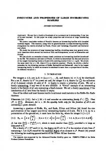
FIG. 5. Optical transmittance of carbon layers deposited onto silica substrates obtained by the implantation of different fluences of carbon ions: 共a兲 5⫻1016 ions cm⫺2, 共b兲 1017 ions cm⫺2, 共c兲 2⫻1017 ions cm⫺2, 共d兲 3 ⫻1017 ions cm⫺2 and a subsequent annealing in vacuum.
the surface, finally appears on the surface when the fluence increases. The observation of the carbon onions during AFM characterization of the surface is thus attributed to the erosion of the silver resulting from ion-beam sputtering rather than to a diffusion of carbon onions toward the surface. The fact that the facets of the silver grains are smoother after than prior to the implantation process also supports this proposal. Finally, a quite uniform carbon onion layer, which keeps the memory of the silver film shape, is characterized after the silver evaporation. Same kinds of observations were made after ion implantation and silver removal on silica substrates.
IV. OPTICAL PROPERTIES
FIG. 4. AFM images 共tapping mode兲 obtained on Si共100兲 substrates covered by a silver thin film deposited at room temperature 共a兲 subsequently implanted 关fluence (1017 ions cm⫺2)兴 at 500 °C with 120 keV carbon ions; 共b兲 a pure carbon onion layer is finally characterized after a thermal annealing at 850 °C in vacuum 共c兲.
plantation fluence. This result is explained as follows: the carbon onions form in the bulk of the silver substrate due to the very low solubility of carbon in the silver. Due to the quite high energy of the carbon ions, almost all of the carbon ions are implanted in the bulk, far from the silver surface. For instance, a TRIM simulation35 indicates that the projected range of 120 keV carbon ions into silver is close to 140 nm. Nevertheless, due to the preferential sputtering of silver, the carbon onions formed inside the silver matrix, but close to
The optical transmittance spectra as a function of the implanted fluence are shown in Fig. 5. The fact that the transmittance decreases when the fluence increases is simply explained by the increase of the average thickness of the carbon layer. Indeed, by assuming that the carbon layer has a density close to that of graphite 共2.25 g cm⫺3兲, it is possible to estimate an equivalent thickness e 共in nm兲 of a deposited dense carbon layer from the relation e⫽ /(11.3⫻1015) 关where is the implanted fluence 共ions cm⫺2兲兴. For the different fluences presented in Fig. 4 the equivalent thickness of the carbon layers varied from about 4 to 26 nm. The second important remark that can be made from this figure concerns the evolution of the absorption peak position. If only a small peak centered around 265 nm can be observed for the lowest fluence (0.5⫻1017 ions cm⫺2), a second peak close to 225 nm comes out for the highest fluences 共1, 2, and 3 ⫻1017 ions cm⫺2兲.
Downloaded 23 Jan 2002 to 134.76.86.158. Redistribution subject to AIP license or copyright, see http://ojps.aip.org/japo/japcr.jsp
1564
Cabioc’h et al.
J. Appl. Phys., Vol. 91, No. 3, 1 February 2002
To better understand the origin of these two absorption peaks, comparisons between the experimental optical transmittances and theoretical simulations were undertaken. The optical properties of the carbon onions were described using a continuous-medium dielectric approximation25 assuming that the effective dielectric function of the onion layer follows the Clausius–Mossotti relation
冉 冊
⑀ ⫽ ⑀ e 1⫹
f␣
1⫺
f␣
,
共1兲
3
where ⑀ e is the dielectric function of the medium external to the onions, ␣ is the dipolar polarizability of the onions in units of ⑀ 0 V, V being the onion volume, and f is the filling fraction. Since the carbon onions present no inner cavity, the following expression24 was used for ␣:
␣ ⫽3
u ⑀ 储⫺ ⑀ e u ⑀ 储 ⫹2 ⑀ e
t共 兲⫽
共2兲
u⫽ 共 冑1⫹8 ⑀⬜ / ⑀ 储 ⫺1 兲 /2,
Re u⬎0,
共3兲
where ⑀⬜ and ⑀ 储 are the principal components of the dielectric tensor for the graphite in the directions perpendicular and parallel to the c axis. It is important to note that in the nonretarded approximation used here, the polarizability per volume unit ␣, and therefore the optical transmittance does not depend on the diameter of the onions. This is in agreement with the results obtained by Pichler et al.36 who showed that the onions’ dielectric response is very similar, close to the graphite one, when their size was varied from 4 to 8 nm. The transmittance of the effective layer 共effective thickness d⫽e/ f 兲 deposited on a thick silica substrate 共refractive index n s 兲, was computed using a standard electromagnetism formula. A generalization of a formulation that can be found in standard textbooks,37 applied to the case where the media on both sides of the film are different, yields to a transmission coefficient of the film at normal incidence given by
共 1⫹n s 兲 2
兩 共 1⫹n s 兲 cos共 2 冑⑀ d/ 兲 ⫺i 共 冑⑀ ⫹n s / 冑⑀ 兲 sin共 2 冑⑀ d/ 兲 兩 2
whereas the dielectric principal components ⑀⬜ and ⑀ 储 of graphite were taken from Draine and Lee’s,38,39 a constant index n s ⫽1.65 was used to fit the average value 0.94 of the silica substrate transmittance. During TEM characterizations of the samples, a residual disordered graphitic carbon component was observed in the voids between the carbon onions. This component was introduced in the simulation of the transmittance spectra as an effective medium, whose dielectric function is equal to 1/3 the trace of the dielectric tensor of the graphite. This approximation corresponds to randomly oriented microscopic units of graphite that are the carbon residues graphitized during the annealing of the samples at 850 °C. The dielectric function of the medium external to the onions was then described by
⑀ e ⫽ 共 1⫺c 兲 ⫹c 共 2 ⑀⬜ ⫹ ⑀ 储 兲 /3,
with
,
共4兲
electron transition from bounding to antibounding states 共 plasmon兲. It is interesting to note that the imaginary part of the polarizability of an isolated carbon onion computed from Eq. 共2兲 has a peak at ⫽0.21 m that corresponds to a maximum of the absorption cross section of the carbon on-
共5兲
where c is the volume concentration of the residual carbon in the voids. To illustrate the effect of introducing this residual carbon component, Fig. 6 shows the evolution of the calculated transmittance curves when the concentration c of residual graphite in the voids increases. The equivalent thickness layer was kept fixed at 30 nm with a filling fraction f ⫽0.6, a value that corresponds to an implanted fluence close to 2 ⫻1017 ions cm⫺2. At first, one can note that when no residual carbon is introduced only an absorption peak close to 225 nm is obtained. It clearly shows that the experimental peak observed to be close to this position comes from the presence of the carbon onions. This peak corresponds to a collective
FIG. 6. Simulated optical transmittance of carbon onion layers containing different volume concentration c of residual graphite between the onions: 共a兲 c⫽0%, 共b兲 c⫽4%, 共c兲 c⫽8%, and 共d兲 c⫽12%.
Downloaded 23 Jan 2002 to 134.76.86.158. Redistribution subject to AIP license or copyright, see http://ojps.aip.org/japo/japcr.jsp
Cabioc’h et al.
J. Appl. Phys., Vol. 91, No. 3, 1 February 2002
FIG. 7. Optical transmittance and corresponding simulated curves 共see Table I for the parameters used for the simulation兲 of carbon onion layers obtained by carbon ion implantations at 500 °C with different fluences: 共a兲 1017 ions cm⫺2, 共b兲 2⫻1017 ions cm⫺2, and 共c兲 3⫻1017 ions cm⫺2. For a better clarity, curve 共c兲 was downshifted 共⫺0.1兲.
ions and, therefore, to a minimum of the transmittance but packing the carbon onions together shifts the transmittance minimum to the red.25 When the concentration c of residual carbon in the voids increases a second peak appears at a position close to 265 nm, whereas the carbon onion signature progressively disappears. Therefore, on the basis of this model but also from the HRTEM micrographs, we propose that the experimental absorption peak originates in the presence of this residual disordered graphitic phase. The model proposed here can be considered as a first approach to understand the optical transmittance of the carbon onion layers since the following considerations must be taken into account. At first, the model is based on the Clausius–Mossotti equation that applies strictly to point-like dipoles located on a cubic structure. Corrections arising from multipole orders higher than two must be considered in the case of dielectric spheres as it is considered here 共the quadrupoles play no role since their summation on a cubic lattice vanishes兲.40 These corrections were not included in the model since the assumption that the onions are located on a cubic lattice has probably more severe effects. Furthermore, there are many uncertainties on the dielectric function of graphite, especially for the out-of-plane component ⑀ 储 and this constitutes another source of error.41,42 Despite these restrictions, this model gives interesting insights to better understand the origin of the different absorption peaks as described above. Furthermore, more quantitative information can be obtained by fitting the experimental curves. So, Fig. 7 shows three experimental transmittance curves and their corresponding simulations, whereas the parameters used for the simulation are gathered in Table I. Con-
1565
cerning these last parameters, it is important to note that the values of the effective thickness and the filling fraction used allow us to obtain an equivalent thickness whose value is close to the one corresponding to the implanted fluence. Furthermore, the value of the filling fraction f of the carbon onions layers was kept constant ( f ⫽0.6) so that the minimum of the optical transmittance occurs at the experimental value of 225 nm. Finally, the concentration of graphitic residues in the voids was adjusted to fit the transmittance curves around ⫽265 nm, where some experimental spectra show a shoulder. The agreement with the experimental data is fair even if noticeable differences exist in the wavelength interval 300–700 nm. Despite these discrepancies, the adjustment of the parameters gives a coherent picture of what the implanted layer is constituted. At low fluence, the presence the graphitic residues mask the optical response of the carbon onions even if its amount is quite low. Such a low fraction of residual graphite can hardly be estimated by HRTEM due to the two-dimensional projection picture given by TEM but also because this carbon material presents very low amorphous-like contrasts as compared to the carbon onions which are always in Bragg diffraction conditions. The simulations presented here show that the optical responses of the carbon onion layers are very sensitive to the presence of residual carbon. The actual proportion of residue with respect to the deposited carbon is c(1⫺ f )/ 关 f ⫹c(1⫺ f ) 兴 . With f ⫽0.6 and c⫽0.08, this proportion is close to 5%. Besides, this high sensitivity makes it possible to estimate the weight of the nononion component, which otherwise is difficult to determine. Furthermore, the present analysis of the optical spectra indicates that the carbon residues mainly form at the beginning of the implantation process. This is confirmed by independent characterizations 共HRTEM, nuclear reactions analysis兲 performed on bulk silver samples implanted with low C fluences 共work in progress兲. Abe43 also observed during in situ TEM observations that the residual amorphous phases growth takes place mainly on grain boundaries at the beginning of the implantation 共i.e., for low fluences兲 in copper substrates. After a fluence close to 1017 ions/cm2, the formation of carbon residues stops while the carbon onions growth continues. Indeed, the quantity of residual graphite 共i.e., fluence⫻proportion of residual graphite兲 deduced from the parameters used for the simulation remains constant when the fluence increases. This phenomenon is attributed to a preferential diffusion of the implanted carbon atoms toward the already formed carbon onions that are very efficient sinks to carbon precipitation. The stresses that exist close to the onions can constitute the driven force for this preferential diffusion. V. TRIBOLOGICAL PROPERTIES
Experiments devoted to the determination of the friction coefficient of pure carbon onion layers deposited onto iron steel or Si substrates were attempted. Unfortunately, due to the very low thickness of the carbon layers, it quickly appears that the macroscopic apparatus used for this study was inappropriate. Therefore, the evolution of the friction coeffi-
Downloaded 23 Jan 2002 to 134.76.86.158. Redistribution subject to AIP license or copyright, see http://ojps.aip.org/japo/japcr.jsp
1566
Cabioc’h et al.
J. Appl. Phys., Vol. 91, No. 3, 1 February 2002
FIG. 8. 共a兲 Evolution of the friction coefficient for a pure silver layer 关curve 共1兲兴 and of a composite silver/carbon onions thin film 关curve 共2兲兴 deposited onto a 304 L iron steel substrate. 共b兲 Evolution of the friction coefficient for a virgin 共100兲 silicon substrate 关curve 共1兲兴 and of composite silver/carbon onions thin films 共curve 共2兲兲 (fluence⫽5⫻1016 ions cm⫺2), and 共3兲 (fluence⫽3⫻1017 ions cm⫺2) deposited onto a silicon substrate. In both cases 5000 rotations correspond to a sliding distance of about 400 m.
cient as a function of the number of rotations of the pin was similar for a coated or uncoated substrate. In fact, more interesting results were obtained for composite silver/onion films deposited onto Si or iron steel substrates. Figure 8 shows the evolution of the friction coefficient as a function of the number of rotations for different composite layers deposited onto stainless steel and silicon substrates. For both cases, a characteristic friction coefficient of 0.2 is obtained at the beginning of the experiment. This value was also obtained for a pure polycrystalline silver substrate, mirror polished, and studied under the same experimental conditions. Nevertheless, the value of the friction coefficient remains close to 0.2 for only 200 rotations for a pure silver thin film, 300 nm thick, deposited onto an iron steel substrate. After the silver layer is implanted at 500 °C with a high fluence of carbon (8⫻1017 ions cm⫺2), with conditions leading to the formation of onions onto the silver layer, the friction coefficient is still 0.2 but for about 5000 rotations. It thus corresponds to an improvement of the silver coating lifetime by a factor of 15. A similar behavior was observed in the case of silicon substrates for all implanted fluences 共5 – 30 ⫻1016 ions cm⫺2 at 500 °C兲 we tested. Nevertheless, in the case of silicon substrates, this improvement of the tribological properties of the composite structure is attributed to the formation of a transferred layer on the pin rather than to
good wear behavior of the composite thin film itself. Indeed, as soon as the pin is replaced after some thousands of rotations, the friction coefficient is the same as that of the uncoated substrate. The preliminary results presented here thus reveal that the presence of onion-like structures strongly improves the wear behavior of the silver thin film. Nevertheless, the friction coefficient remains high. This can be simply explained by considering that the carbon onions embedded inside the metal cannot roll and the silver presence governs the friction behavior. The reinforcement of the matrix allowing better wear behavior can be considered as an interesting new result but it remains very far from the results that can be obtained with pure carbon coatings such as diamond-like carbon films.44 Furthermore, the quantity of carbon onions 共typically some tens of micrograms兲 is too low to obtain a good comprehension of the lubricant properties of carbon onions by using the macroscopic apparatus we used in the present study. To better investigate the tribological properties of our carbon onion thin films, nanotribology experiments we do not have at our disposal will be powerful. Cohen et al.45 recently studied the friction behavior of MoS2 nanoparticles having an onion-like structure using scanned probe microscope techniques. These experiments confirm that onion-like structures are excellent lubricants due to their convenient size 共15– 60 nm兲 and shape that facilitate rolling friction. Concerning carbon onions, such experiments could also give interesting new insights. For instance they could demonstrate that the carbon onions embedded in the silver cannot roll, explaining the quite high friction coefficient we obtained. Furthermore, it would be interesting to study the influence of partial coalescence of the onions, as visible in Fig. 2, that can contribute to deteriorating the tribological properties. VI. CONCLUSION
Pure carbon onion thin films deposited onto various substrates were obtained with a three-step technique. After the deposition of a thin silver film onto the substrate, carbon ion implantations at high temperature were performed to synthesize carbon onions inside the film. The third step consists of evaporating the silver component by a thermal annealing in vacuum. HRTEM and AFM characterizations of the samples confirm the formation of spherical carbon onions. The optical transmittance properties of the carbon onions layers so produced were analyzed on the basis of the dielectric theory. Two absorption peaks centered at 225 and 265 nm are, respectively, attributed to the carbon onions and graphitic residues. The evolution of the transmittance spectra as a function of the implanted fluence reveals that the graphitic residues are mainly formed at the beginning of the implantation process. Macroscopic tribological tests show that the presence of carbon onions strongly improves the wear behavior of the silver thin films. ACKNOWLEDGMENTS
The authors acknowledge M. F. Denanot who performed the HRTEM analysis. This work has been partly funded by the interuniversity research project on reduced dimensional-
Downloaded 23 Jan 2002 to 134.76.86.158. Redistribution subject to AIP license or copyright, see http://ojps.aip.org/japo/japcr.jsp
Cabioc’h et al.
J. Appl. Phys., Vol. 91, No. 3, 1 February 2002
ity systems 共PAI P4/10兲 of the Belgian Office for Scientific, Cultural and Technical affairs. It has also benefitted from financial support from the ‘‘Actions Inte´gre´es Franco– Belges Tournesol’’ 共Project No. 98.034兲. L. H. was supported by the Belgian FNRS. 1
H. W. Kroto, J. R. Heath, S. C. O’Brien, R. F. Curl, and R. E. Smalley, Nature 共London兲 318, 162 共1985兲. 2 S. Iijima, Nature 共London兲 354, 56 共1991兲. 3 C. Dekker, Phys. Today 52, 22 共1999兲. 4 D. Ugarte, Nature 共London兲 359, 707 共1992兲. 5 K. R. Bates and G. E. Scuseria, Theor. Chem. Acc. 99, 29 共1998兲. 6 J. P. Lu and W. Yang, Phys. Rev. B 49, 11421 共1994兲. 7 A. Maiti, C. J. Brabec, and J. Bernholc, Phys. Rev. Lett. 70, 3023 共1993兲. 8 J. L. Mora´n-Lo´pez, K. H. Bennemann, M. Cabrera-Trujillo, and J. Dorantes-Da´villa, Solid State Commun. 89, 977 共1994兲. 9 M. Terrones, W. K. Hsu, J. P. Hare, H. W. Kroto, H. Terrones, and D. R. M. Walton, Philos. Trans. R. Soc. London, Ser. A 354, 2025 共1996兲. 10 D. Toma`nek, W. Zhong, and E. Krastev, Phys. Rev. B 48, 15461 共1993兲. 11 F. Banhart and P. M. Ajayan, Nature 共London兲 382, 433 共1996兲. 12 W. A. De Heer and D. Ugarte, Chem. Phys. Lett. 204, 480 共1993兲. 13 V. L. Kuznetsov, A. L. Chuvilin, Y. B. Butenko, I. Y. Mal’kov, and V. M. Titov, Chem. Phys. Lett. 222, 343 共1994兲. 14 O. Mamezaki, H. Adachi, S. Tomita, M. Fujii, and S. Hayashi, Jpn. J. Appl. Phys., Part 1 39, 6680 共2000兲. 15 X. H. Chen, F. M. Deng, J. X. Wang, H. S. Yang, G. T. Wu, X. B. Zhang, J. C. Peng, and W. Z. Li, Chem. Phys. Lett. 336, 201 共2001兲. 16 T. Cabioc’h, J. P. Rivie`re, and J. Delafond, J. Mater. Sci. 30, 4787 共1995兲. 17 T. Cabioc’h, J. C. Girard, M. Jaouen, M. F. Denanot, and G. Hug, Europhys. Lett. 38, 471 共1997兲. 18 T. Cabioc’h, M. Jouen, M. F. Denanot, and P. Bechet, Appl. Phys. Lett. 73, 3096 共1998兲. 19 L. Henrard, F. Malengreau, P. Rudolf, K. Hevesi, R. Caudano, Ph. Lambin, and T. Cabioc’h, Phys. Rev. B 59, 5832 共1999兲. 20 V. L. Kuznetsov, Y. V. Butenko, A. L. Chuvilin, A. I. Romanenko, and A. V. Okotrub, Chem. Phys. Lett. 336, 397 共2001兲.
1567
H. W. Kroto, Nature 共London兲 359, 670 共1992兲. D. Ugarte, Astrophys. J. 443, L85 共1995兲. 23 L. Henrard, Ph. Lambin, and A. A. Lucas, Astrophys. J. 487, 719 共1997兲. 24 L. Henrard, A. A. Lucas, and Ph. Lambin, Astrophys. J. 406, 92 共1993兲. 25 A. A. Lucas, L. Henrard, and Ph. Lambin, Phys. Rev. B 49, 2888 共1994兲. 26 E. L. Wright, Nature 共London兲 336, 227 共1988兲. 27 P. Apell, D. Ostling, and G. Mukhapadyay, Solid State Commun. 87, 219 共1993兲. 28 S. Wada, C. Kaito, S. Kimura, H. Ono, and A. T. Tokunaga, Astron. Astrophys. 345, 259 共1999兲. 29 L. Rapoport, Y. Bilik, M. Homyonfer, S. R. Cohen, and R. Tenne, Nature 共London兲 387, 791 共1997兲. 30 M. Chhowalla and G. A. J. Amaratunga, Nature 共London兲 407, 164 共2000兲. 31 L. Rapoport, Y. Feldman, M. Homyonfer, H. Cohen, J. Sloan, J. L. Hutchinson, and R. Tenne, Wear 225–229, 975 共1999兲. 32 The Characterization of High Temperature Vapors, edited by J. Margrave 共Wiley, New York, 1967兲. 33 E. Thune, T. Cabioc’h, and M. Jaouen, Mater. Lett. 共to be published兲. 34 E. Thune, the`se de l’Universite´ de Poitiers, 2001. 35 J. F. Ziegler, J. P. Biersack, and U. Littmark, The Stopping and Range of Ions in Solids 共Pergamon, New York, 1985兲. 36 T. Pichler, M. Knupfer, M. S. Golden, J. Fink, and T. Cabioc’h, Phys. Rev. B 63, 155415 共2001兲. 37 C. F. Bohren and D. R. Huffman, Absorption and Scattering of Light by Small Particles 共Wiley, New York, 1983兲, p. 37. 38 B. T. Draine and H. M. Lee, Astrophys. J. 285, 89 共1984兲. 39 B. T. Draine, Princeton Observatory Report, Princeton, 1987. 40 W. T. Doyle, J. Appl. Phys. 49, 795 共1978兲. 41 B. Michel, Th. Henning, C. Ja¨ger, and U. Kreibig, Carbon 37, 391 共1999兲. 42 E. Tosati and F. Bassani, Nuovo Cimento 65, 161 共1970兲. 43 H. Abe, Diamond Relat. Mater. 10, 1201 共2001兲. 44 H. Gonnord, M. Jaouen, J. Delafond, and T. Girardeau, Wear 231, 38 共1999兲. 45 S. R. Cohen, Y. Feldman, H. Cohen, and R. Tenne, Appl. Surf. Sci. 144– 145, 603 共1999兲. 21 22
Downloaded 23 Jan 2002 to 134.76.86.158. Redistribution subject to AIP license or copyright, see http://ojps.aip.org/japo/japcr.jsp