pretation of the structure function is available. The situation is even more critical for a generic thermal problem, hereafter referred to as multi-directional heat-flow.
Structure Function Representation of Multi-Directional Heat-Flows Lorenzo Codecasa, Dario D’Amore and Paolo Maffezzoni Dipartimento di Elettronica e Informazione, Politecnico di Milano, 20133 Milan, Italy e-mail: {codecasa, damore, pmaffezz}@elet.polimi.it, fax: +39 02 2399 3412 Abstract — A relation is established between the structure function of the RC transmission line modeling a one-port passive distributed thermal network and the spatial distribution of thermal properties in heat diffusion problems with generic multidirectional heat-flows.
heat-flow. For such a thermal problem, the structure function can still be associated to a one-port passive distributed thermal network, as precised in [8]. However the relation between the structure function and the spatial distribution of thermal properties in the thermal problem is not known.
1
In this paper, which extends the results in [5], the structure function of a one-port passive distributed thermal network modelling a multidirectional heat-flow is considered. A procedure for exactly determining a structure function from a thermal response is shown. Moreover an exact relation between the structure function of the equivalent RC transmission line on one hand and the spatial distribution of thermal properties in the thermal problem on the other hand is established. As a result a physical interpretation of the structure function is obtained.
Introduction
Distributed thermal networks are widely used for modeling heat conduction problems in components and packages. Structure functions, originally introduced by V. Szekely et al. [1], are means for characterizing the responses of one-port distributed thermal networks in terms of equivalent RC transmission lines. In fact, as recently precised in [8], the response of a one-port passive distributed thermal network modeling a generic thermal problem coincides with the response of a proper RC transmission line defined by a structure function. Since their introduction, structure functions have been used for inferring on the spatial distributions of thermal properties in components and packages [1–4]. For a one-dimensional thermal problem in which power is injected at one boundary and temperature rise is measured at the same boundary, a one-port passive distributed thermal network naturally arises. In this case, the cumulative resistance and capacitance of the RC transmission line are exactly the cumulative thermal resistance and capacitance from the boundary at which power is injected. In this case, hereafter referred to as one-directional heat flow, by determining the structure function from the thermal response of the distributed thermal network, precise information on the spatial distribution of thermal properties is recovered [13]. No procedure is reported in literature for exactly determining a structure function from a thermal response. Moreover in practice, this technique is used in applications which are only approximated by one-directional heat-flows. The more inaccurate is this approximation, the more inaccurate is the recovered information on the spatial distribution of thermal properties. That is because no exact interpretation of the structure function is available. The situation is even more critical for a generic thermal problem, hereafter referred to as multi-directional
Precisely, firstly the problem of relating the structure function of an RC transmission line to the spatial distribution of material properties of the heat diffusion problem is transformed into the equivalent problem of relating the structure function of an LC transmission line to the spatial distribution of material properties of a wave propagation problem. Secondly the relation between the structure function and the response of such LC transmission line is outlined. Lastly a family of wave fronts and a family of rays are naturally associated to the wave propagation problem. The structure function is related to the thermal properties along rays between wave-fronts. Using this result, a strategy is proposed for naturally exploiting structure functions in practical applications. The rest of this paper is organized as follows. In section 2 the definition of structure function is recalled. In section 3 the companion wave propagation problem is introduced. A procedure for determining the structure function from the wavepropagation problem is outlined in section 4 and applied in 5. Wave-fronts and rays of the wave propagation problem and the relation between structure function and spatial distribution of material properties is shown in section 6 and applied in section 7.
2
RC Transmission Line Representation of One-Port Passive Distributed Thermal Network
We refer to a generic component or package that extends in a bounded spatial region Ω. As is well known, the relation between the generated power density G(r, t) and the temperature rise distribution u(r, t) with respect to ambient temperature and the heat flux density q(r, t) is ruled by the First Principle of Thermodynamics and by Fourier’s law as follows
PSfrag replacements
∂v (r, t) = G(r, t), ∂t q(r, t) = −k(r)∇u(r, t), ∇ · q(r, t)) + c(r)
(2)
(3)
in which h(r) is the heat transfer coefficient and ν(r) is the unit vector outward normal to ∂Ω. The initial condition is assumed to be zero u(r, 0) = 0.
C1
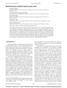
Figure 1: Equivalent passive RC transmission line. singular RC transmission line is ruled by equations
(1)
in which c(r) is the volumetric heat capacity and k(r) is the thermal conductivity. These equations are completed by the conditions on the boundary ∂Ω of Ω and by the initial condition for the temperature rise u(r, t). The boundary conditions, assumed of Robin’s type, are q(r, t) · ν(r) = h(r)u(r, t),
T (t)
K(R)
R2
P (t)
(4)
A one-port passive distributed thermal network is defined as in [8–10], by introducing the power P (t) and the temperature rise T (t) measured at its port. The power P (t) determines the power density G(r, t) as G(r, t) = g(r)P (t) (5) in which g(r) is a function of support Σ. The temperature rise T (t) is Z T (t) = g(r)u(r, t) dr. (6) Ω
The relation between the power P (t) and the temperature rise T (t) is represented, in the time domain, by a power impulse thermal response zRC (t) and, in the complex angular frequency domain, by a thermal impedance function ZRC (s). As proved in [8], the response of a one-port passive distributed thermal network is the short circuit input response of a passive RC transmission line of total resistance R0 = ZRC (0). Any definition of the port temperature T (t) different from Eq. (6) in general leads to an active distributed thermal network, which clearly is not equivalent to a passive RC transmission line as shown in Fig. 1. The non-
∂T (x, t), ∂x ∂T ∂P (x, t) = −c(x) (x, t) ∂x ∂t in which k(x) and c(x) are the thermal conductivity and volumetric heat capacity at coordinate x along the line, P (x, t) and T (x, t) are the power and temperature rise at coordinate x along the line. Different choices of the x coordinate correspond to different k(x) and c(x) and to different representations of the non-singular RC transmission line. Two representations are hereafter considered. In the travel time representation [14, 15], the coordinate x = τ is chosen is such a way that k(x) = c(x) = A(τ ) so that ∂T (τ, t), P (τ, t) = −A(τ ) ∂τ ∂T ∂P (τ, t) = −A(τ ) (τ, t) ∂τ ∂t In the structure function representation [6, 7], the coordinate x = R is chosen in such a way that k(x) = 1 and c(x) = K(R) so that P (x, t) = −k(x)
∂T (R, t), ∂R ∂T ∂P (R, t) = −K(R) (R, t). ∂R ∂t Thus R is the cumulative resistance along the line and Z R C(R) = K(R) dR P (R, t) = −
0
is the cumulative capacitance. Such representations are equivalent. In fact from the travel time representation the structure function representation is recovered as follows Z τ dτ R= , (7) 0 A(τ ) K(R) = A2 (τ ), Z τ C(R) = A(τ ) dτ. 0
(8)
(9)
Similarly from the structure function representation the travel time representation is recovered as follows Z Rp τ= K(R) dR, 0 p A(τ ) = K(R).
PSfrag replacements
3
V (t)
K(L)
R2
I(t)
C1
Companion Wave Propagation Problem
The heat diffusion problem of Eqs. (1)-(4) and the one-port passive distributed thermal network of Eqs. (5), (6) can be formally associated to a companion wave propagation problem and to a companion one-port passive distributed network. Precisely the wave propagation problem in Ω is, ∂j (r, t) = −k(r)∇v(r, t) ∂t ∂v ∇ · j(r, t)) + c(r) (r, t) = G(r, t), ∂t
(10) (11)
with boundary conditions, on ∂Ω, ∂j (r, t) · ν = h(r)v(r, t), ∂t
(12)
and with initial conditions, in Ω, v(r, 0) = 0,
j(r, 0) = 0.
(13)
The companion one-port passive distributed network is defined by introducing the current I(t) and the voltage V (t) measured at its port, as follows. The current I(t) determines G(r, t) as G(r, t) = g(r)I(t).
(14)
The voltage V (t) is V (t) =
Z
g(r)v(r, t) dr.
(15)
Ω
The relation between the current I(t) and the voltage V (t) is represented, in the time domain, by an impulse response zLC (t) and, in the complex angular frequency domain, by an impedance function ZLC (s). Since ZLC (s) = s ZRC (s2 ), the response of this one-port distributed network is the short circuit input response of a passive LC transmission line obtained from the passive RC transmission line of Fig. 1 by substituting the resistors with inductors, as shown in Fig. 2. This passive LC transmission line is in general singular since it consists of the cascade connection of a
Figure 2: Equivalent passive LC transmission line. lumped LC ladder and of a non-singular LC transmission line ruled by equations ∂I ∂V (x, t) = −k(τ ) (x, t), ∂t ∂x ∂I ∂V (x, t) = −c(x) (x, t) ∂x ∂t in which I(x, t) and V (x, t) are the current and voltage at coordinate x along the line. Different choices of the x coordinate correspond to different k(x) and c(x) and to different representations of the non-singular LC transmission line. Two representations are hereafter considered. In the travel time representation [14, 15] the coordinate x = τ is chosen in such a way that k(x) = c(x) = A(τ ) so that ∂V ∂I (τ, t) = −A(τ ) (τ, t), (16) ∂t ∂τ ∂V ∂I (τ, t) = −A(τ ) (τ, t) (17) ∂τ ∂t In the structure function representation [3], the coordinate x = L is chosen in such a way that k(x) = 1 and c(x) = K(L) so that ∂V ∂I (L, t) = − (L, t), ∂t ∂L ∂I ∂V (L, t) = −K(L) (L, t). ∂L ∂t Thus L is the cumulative inductance along the line and Z L C(L) = K(L) dL 0
is the cumulative capacitance. Such representations are equivalent. In fact from the travel time representation the structure function is recovered as follows Z τ dτ L= , 0 A(τ ) K(L) = A2 (τ ), Z τ C(L) = A(τ ) dτ. 0
Similarly from the structure function representa- in which tion, the travel time representation is recovered as follows Z Lp It results in K(L) dL, τ= Z 0 p A(τ ) = K(L).
The spatial distributions of material properties k(r) and c(r) are common to the heat diffusion problem and to the companion wave propagation problem. Similarly the structure function representation is common to the one-port passive distributed thermal network and to the companion one-port passive distributed network. Hereafter, in order to relate the structure function to the spatial distributions of thermal properties k(r) and c(r), the companion wave propagation problem and the companion one-port passive distributed network are considered. 4
Procedure for Determining Structure Functions
The lumped LC ladder in Fig. 2 can be determined by applying the continuous fraction expansion of the ZLC (s) impedance. Precisely for k = 1, 2, . . . C2k−1 = lim 1/sZ2k−2 (s) s→∞
L2k = lim Z2k−1 (s)/s s→∞
in which Z0 (s) = ZLC (s) and Z2k−1 (s) = 1/(1/Z2k−2 (s) − sC2k−1 ), Z2k (s) = Z2k−1 (s) − sL2k . The continuous fraction expansion breaks down after p lumped elements are determined. It can be easily proved that p is the maximum order of the derivatives of zLC (t) with respect to time existing at t = 0. Equivalently p can be related to the spatial regularity of the k(r), c(r) and g(r) functions. The determination of the non-singular LC transmission line in Fig. 2 can be obtained from Zp (s) as follows. It results A(0) = 1/ lim Zp (s). s→∞
−τ ≤ t ≤ τ.
τ
A(τ ) dτ = 0
Z
τ
I(τ, t) dt. 0
By recalling Eqs. (7)-(9), also R, K(R) and C(R) can be recovered from A(τ ). This computation is stopped at τ = τ0 such that R(τ0 ) = R0 . A procedure for determining structure functions is thus established. It has to be noted that if all derivatives of zLC (t) exist at t = 0, then the continuous fraction expansion does not break down. In this case only an infinite lumped LC network is determined. 5
Analytical Example: Part I
A slab of thickness L, area S, thermal conductivity k and volumetric heat capacity c is considered. The slab extends in the region Ω in which 0 ≤ x ≤ L, the power P (t) is uniformly generated within the Σ sub-region of Ω, 0 ≤ x ≤ l ≤ L. On the surface x = L of the boundary ∂Ω the temperature is set to the ambient temperature. On the rest of the boundary ∂Ω the thermal flux is set to zero. According to Eq. (6), the mean temperature rise in Σ is the T (t) temperature rise of a one-port passive distributed thermal network. By means of the procedure outlined in section 4, the structure function representation of the one-port passive distributed thermal network can be derived. The results for some values of l are hereafter reported. From the continuous fraction division one lumped capacitor is derived having capacitance C1 = lSc. By solving the Fredholm integral equation the travel time representation follows from which the structure function representation is obtained. For l = L it results in γ=
1 (1 − 3ρ)
1 3
,
0