SiO2 film is deposited on the interdigital transducer (IDT)/ substrate, the surface of the film always has periodic convex portions of the same thickness as the ...
Japanese Journal of Applied Physics 48 (2009) 07GG02
REGULAR PAPER
Surface Acoustic Wave Duplexer Composed of SiO2 /Cu Electrode/LiNbO3 Structure Having Convex and Concave Portions Yasuharu Nakai, Takeshi Nakao, Kenji Nishiyama, and Michio Kadota Murata Manufacturing, Co., Ltd., Nagaokakyo, Kyoto 617-8555, Japan Received November 17, 2008; accepted February 16, 2009; published online July 21, 2009 The transition bandwidth of 20 MHz between the transmission (Tx: 1850 –1910 MHz) and the receiving (Rx: 1930 –1990 MHz) bands of personal communication service (PCS) handy phones in the United States (US) is very narrow compared with those of other systems. We have already realized surface acoustic wave (SAW) duplexers with sizes of 5:0 � 5:0 � 1:7 and 3:0 � 2:5 � 1:2 mm3 for PCS handy phones in the US with an excellent temperature coefficient of frequency (TCF) by using a shear horizontal (SH) wave on a flattened SiO2 /Cu electrode/36 – 48� YX-LiTaO3 structure and a Rayleigh wave on a SiO2 /Cu electrode/120 –128� YX-LiNbO3 structure. Although the surface of the above-mentioned structures is flattened SiO2 , we have also studied the shape of the SiO2 surface. As a result, in addition to increasing the stop-band width, which corresponds to the reflection coefficient, the TCF and power durability have been improved by forming convex portions on the surface of the SiO2 over the interdigital transducer (IDT) gaps. # 2009 The Japan Society of Applied Physics DOI: 10.1143/JJAP.48.07GG02
1.
Introduction
hm
The transition bandwidth of 20 MHz between the transmission (Tx: 1850 –1910 MHz) and receiving (Rx: 1930 – 1990 MHz) bands of personal communication service (PCS) handy phones in the United States (US) is very narrow compared with those of other systems. To realize a surface acoustic wave (SAW) duplexer for PCS, a SAW substrate with a suitable electromechanical coupling factor, an improved temperature coefficient of frequency (TCF), and a large stop-band width, which corresponds to the reflection coefficient, is required. The TCF of Rayleigh, leaky SAW (LSAW), and boundary acoustic waves is improved by depositing a SiO2 film with a positive TCF on a LiNbO3 (LN) or LiTaO3 (LT) with a negative TCF.1–4) When the SiO2 film is deposited on the interdigital transducer (IDT)/ substrate, the surface of the film always has periodic convex portions of the same thickness as the fingers of the IDT. These large convex portions cause deterioration in the frequency characteristics. In order to avoid this phenomenon, a flattened SiO2 surface with the convex portions removed has been applied to SAW duplexers.5–8) By using flattened SiO2 , we have already realized SAW duplexers with sizes of 3:0 � 2:5 � 1:2 and 2:5 � 2:0 � 0:48 mm3 for PCS handy phones in the US with an excellent TCF by using a shear horizontal (SH) wave on a flattened SiO2 /Cu electrode/36 – 48� YX-LT structure for the Rx filter and the Rayleigh wave on a flattened-SiO2 /Cu electrode/120 –128� YX-LN structure for the Tx filter.5–7) In this study, we attempted to form convex portions on the SiO2 film over the gaps between the IDT fingers instead of over the fingers. As a result, the calculated and measured results showed an increase in the stop-band width and an improvement of the TCF. In addition, the measured results showed that power durability was markedly improved without any deterioration in the frequency characteristics. Although SiO2 /Al electrode/LN structures with convex and concave portions on the SiO2 surface were previously reported,9,10) they were different from the structures and electrodes used in our study, and only some of the various SAW properties of the above-mentioned structures were previously reported.11,12) In this study, we apply their structures to a duplexer device and measure their characteristics.
IDT hm
SiO2
h1
SiO2
IDT
LN
LN
(a)
(b)
SiO2
IDT
h2 h1
SiO2
IDT
LN
LN
(c)
(d)
h2 h1
h2 h1
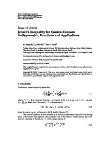
Fig. 1. Various SiO2 /Cu electrode/LN structures (h1 : thickness of basic SiO2 film, h2 : thickness of additional SiO2 film).
2.
Calculation Results of New SiO2 /Cu Electrode/ LiNbO3 Structure
We have already researched and reported a SiO2 /Cu electrode/36 – 48� YX-LT structure and a SiO2 /Cu-electrode/120 –128� YX-LN structure having periodic convex portions with the same thickness as the fingers of the IDT over the IDT fingers, as shown in Fig. 1(a), and having flattened SiO2 over the IDT fingers, as shown in Fig. 1(b).5–8,13) The SiO2 film and Cu electrode were employed in order to compensate the TCF and realize a large stop-band width, respectively. The surface of the SiO2 film is flattened to avoid the deterioration of the frequency characteristics. In this study, in addition to the previously reported structures in Figs. 1(a) and 1(b), we have investigated two new structures having convex portions on the SiO2 film over the gaps in the IDT as shown in Fig. 1(c) and over the fingers of the IDT as shown in Fig. 1(d) to clarify how the characteristics change with the thickness and shape of the additional SiO2 . The thickness of the convex portions is different from the thickness of the IDT in Figs. 1(c) and 1(d). In Fig. 1, the parameter h1 is the thickness of the basic SiO2 film and the parameter h2 is the thickness of the additional SiO2 . The calculated results of the TCF of the resonant and the antiresonant frequencies are shown in Figs. 2(a) and 2(b), respectively, as a function of h2 . In Fig. 2, the substrate is a
07GG02-1
# 2009 The Japan Society of Applied Physics
Jpn. J. Appl. Phys. 48 (2009) 07GG02 5 (b)
-10
(d)
LN
-15
SiO2h1=0.25λ
2
Cu
Cal.
0.08
h2 h1
o
TCF [ppm/ C]
-5 SiO2
0.10
h2 SiO2h1=0.25λ h1
(c)
Coupling factor k
0
Y. Nakai et al.
-20
h2 h1
(d)
-25
h2 h1
0.06
SiO2 Cu
0.04
(b)
h2 h1 (c)
h2 h1
LN
0.02
-30 -35 0.00
0.01λ
0.02λ
0.03λ
0.04λ
0.05λ
0.00 0.00
0.06λ
0.01λ
0.02λ
0.03λ
0.04λ
0.05λ
h2
h2
(a) Fig. 3. Calculated results of the electromechanical coupling factor for various structures.
15
o
TCF [ppm/ C]
5 SiO 2 0 -5
h2 h1
(c)
(b)
SiO2h1=0.25λ
0.10
h2 h1
Cu
-10 -15
h2 h1
(d)
-20 -25 0.00
0.01λ
SiO2h1=0.25λ
h2 h1
(c)
0.08
LN Stop-band width
10
0.02λ
0.03λ
0.04λ
0.06 (d)
0.04
h2 h1
0.02
0.05λ
h2
0.00 0.00
(b)
126� YX-LN, the electrode is a Cu film of thickness 0:04�, h1 is 0:25�, and the metallization ratio is 0.5, where � is the wavelength of the SAW. The finite element method (FEM) was used in the calculations.14) Although the TCF of the antiresonant frequency of structure (d) deteriorates up to h2 ¼ 0:008�, the TCF of every structure improved with increasing h2 as shown in Fig. 2. When structures (b), (c), and (d) with the same values of h1 and h2 , are compared, structure (c) has the best TCF of the antiresonant frequency and (d) has the worst TCF. The calculated results of the electromechanical coupling factor are shown in Fig. 3 as a function of h2 for h1 ¼ 0:25�. The electromechanical coupling factor of structure (d) decreases markedly with increasing h2 . On the other hand, the decreases for structures (b) and (c) are very small. The calculated results of the stop-band width are shown in Fig. 4 as a function of h2 for h1 ¼ 0:25�. The stop-band width of structure (d) decreases markedly with increasing h2 . The decrease for structure (b) is very small. On the other hand, the stop-band width of structure (c) increases with increasing h2 . Figure 5 shows the calculated results of the stop-band width of the SiO2 /Cu electrode/42� YX-LT structure. In Fig. 5, the thickness of the Cu electrode film is 0:04�, h1 is 0:20�, and the metallization ratio is 0.5. In Fig. 5, the stop-band width of structure (c) decreases with increasing h2 . The dependence of the stop-band width on the
(b)
SiO2 Cu
h2 h1 LN
0.01λ
0.02λ
0.03λ
0.04λ
0.05λ
h2 Fig. 4. Calculated results of the stop-band width for various structures on LN.
0.10
SiO2h1=0.25λ
Cal.
h2 h1
0.08 Stop-band width
Fig. 2. Calculated results of the TCF [(a) resonant frequency and (b) antiresonant frequency] of various structures (h1 : thickness of basic SiO2 film, h2 : thickness of additional SiO2 film).
Cal.
(d) 0.06
SiO2
(c) 0.02 0.00 0.00
h2 h1
(b) Cu
0.04
0.01λ
LN
h2 h1 0.02λ
0.03λ
0.04λ
0.05λ
h2 Fig. 5. on LT.
Calculated results of stop-band width for various structures
SiO2 film thickness h2 varies with the mode of the SAW, the substrate, and the structure. At present, it is difficult to theoretically discuss the mechanism of the dependence of the TCF, the electromechanical coupling factor, and the stop-band width on the shape of the SiO2 surface, which has been left as future research. Our results show that structure (c) is effective for improving the TCF and increasing the stop-band width without a large reduction of the electromechanical coupling
07GG02-2
# 2009 The Japan Society of Applied Physics
Jpn. J. Appl. Phys. 48 (2009) 07GG02 10000 1000
Meas. (c)
h2 h1
Y. Nakai et al.
(b) SiO2
5
h2 h1
Cu LN
h2 h1
(c)
SiO2h1=0.25λ
-10
o
TCF [ppm/ C]
(A)
10
spurious response due to SH wave
1
SiO2 h2=0.02λ
(B)
0.1
90 45 0 -45
0.01 1800
(b) (c)
-5
Phase[o]
|Z| [Ω]
100
Meas.
0
1850
1900 1950 Frequency [MHz]
-15 Cal.
-20 (b) SiO2 Cu
-25
h2 h1
-30
-90 2000
LN
-35 0.00
0.01λ
0.02λ
0.03λ
0.04λ
0.05λ
h2
(a)
Fig. 6. Frequency characteristics of the one-port resonators composed of structure (b) and structure (c).
15 Meas. 10
factor. Structure (c) has another advantage compared with structure (b) as mentioned later. TCF [ppm/ C]
h2 h1
(c)
SiO2h1=0.25λ
0
o
Application to a One-Port Resonator
-5
Cal.
-10
(b)
SiO2 Cu
-15 -20
h2 h1 LN
-25 0.00
0.01λ
0.02λ
0.03λ
0.04λ
0.05λ
h2
(b) Fig. 7. Measured results of the TCF [(a) resonant frequency, (b) antiresonant frequency] of structures (b) and (c) (h1 : thickness of basic SiO2 film, h2 : thickness of additional SiO2 film).
0.10 Cal. 0.08 2
We fabricated two one-port resonators composed of structures (b) and (c) using a 126� YX-LN substrate. The wavelength (�) of both resonators is 1.95 mm, the number of IDT pairs is 120, the aperture is 32 mm (16:4�), the Cu electrode thickness is 0:04�, h1 is 0:25�, and h2 is 0, 0:01�, 0:02�, or 0:03�. Figure 6 shows the frequency characteristics of the oneport resonators of structures (b) and (c) with h2 ¼ 0:02�. The resonator with structure (c) has very similar characteristics to that with structure (b). The spurious response of the SH-LSAW wave can be suppressed by optimizing the rotated cut angle of the LN substrate. The measured results of the TCF of the resonant and antiresonant frequencies for h1 ¼ 0:25� are shown in Fig. 7 as a function of h2 . Both TCF are improved with increasing h2 in both structures. This result has the same tendency as the calculated result shown in Fig. 2. The measured results of the electromechanical coupling factor of the one-port resonator are shown in Fig. 8 as a function of h2 , where h1 is 0:25�. Although the calculated value of the electromechanical coupling factor shown in Fig. 3 slightly decreases with increasing h2 , the experimental results of the electromechanical coupling factor hardly decrease with increasing h2 . The measured results of the stop-band width are shown in Fig. 9 as a function of h2 for h1 ¼ 0:25�, where the stop-band width is the normalized value of the bandwidth between (A) and (B) shown in Fig. 6, where (A) is the resonant frequency and (B) is the frequency of the spurious response caused by the upper limit of the stop-band. The stop-band width of structure (b) decreases with increasing h2 . On the other hand, the stop-band width of structure (c) increases with increasing h2 . The resonator with a wide stop-band is advantageous for the parallel resonator of a ladder-type filter, because a small stop-band causes a ripple in the passing band. The stop-band width strongly correlates with the reflection coefficient, for example, the stop-band widths of structure (c) of 0.091, 0.100, and 0.108 correspond to the reflection coefficients of 0.056, 0.062, and 0.067, respectively.
Coupling factor k
3.
5
(b) (c)
(c)
0.06
(b) h2 h1 SiO2
h2 h1
Cu
0.04
LN 0.02 0.00 0.00
Meas Cal. (b) (c)
SiO2h1=0.25λ 0.01λ
0.02λ
0.03λ
0.04λ
0.05λ
h2 Fig. 8. Measured results of the electromechanical coupling factor of structures (b) and (c).
4.
Application to a US-PCS Duplexer
We have already succeeded in the mass production of a USPCS duplexer using structure (b). As shown by the measured result of the one-port resonator in Fig. 10, the electromechanical coupling factor of structure (b) for h2 ¼ 0 is slightly larger than that of structure (c) for h2 ¼ 0:02�. Therefore, structure (c) can achieve the bandwidth of the US-PCS duplexer, and we applied structure (c) to the Tx filter of the US-PCS SAW duplexer. On the other hand, the
07GG02-3
# 2009 The Japan Society of Applied Physics
Jpn. J. Appl. Phys. 48 (2009) 07GG02
Normalized Stop-band width
Meas
h2 h1
(c)
Cal.
(b) 0.08 (c)
4
SiO2h1=0.25λ
Meas. Normalized lifetime
0.10
Y. Nakai et al.
0.06 (b) 0.04
SiO2 Cu
h2 h1
0.02
Cal.
SiO2 h1=0.25λ
3 (b) 2
h2 h1 LN
Cu
0.01λ
0.02λ
0.03λ
0.04λ
1 0.00
0.05λ
0.01λ
Fig. 9. Measured results of the stop-band width of structures (b) and (c).
20
h2 h1 LN
h2 h1
1700
IDT SiO2 h2=0.03λ
1900 2000 Frequency [MHz]
-0.04λ
-0.08λ 0.0
2100
SiO2 h2=0
h2=0.02λ
LN
LN h2 h1
8 1800
SiO2 h1=0.25λ
0 h2=0.01λ
6
80
0.04λ
0.04λ
2 4
(c)
Cal.
SiO2
0
Depth
Insertion Loss [dB]
SiO2 Cu
0.03λ
Fig. 11. Power durability of the one-port resonator of structures (b) and (c).
0.08λ
(b)
Meas.
60
LN
0.02λ h2
h2
40
h2 h1
SiO2
LN
0.00 0.00
0
(c)
0.2
0.4 0.6 0.8 1.0 1.2 Shear Stress τ 12 (Normalized)
1.4
Fig. 10. Frequency characteristics of the Tx filters of the US-PCS duplexer composed of structures (b) and (c).
Fig. 12. Calculated shear stress of structure (c).
Rx filter is used in the SiO2 /Cu electrode/36 – 48� YX-LT structure, similarly to in previous reports.1,2) Figure 10 shows the frequency responses of the Tx filter of the US-PCS SAW duplexer composed of structures (b) and (c) for h1 ¼ 0:25�, where h2 for structures (b) and (c) is 0 and 0:02�, respectively. The two characteristics are very similar at room temperature. The TCF of structure (c) is about �10 ppm/� C. Thus, the TCF of structure (c) with h2 ¼ 0:02� was improved by about 3 – 5 ppm/� C compared with that of structure (b). Kadota and Kondoh reported that the propagation loss was improved by polishing the ZnO surface and removing the convex portions on the ZnO film and roughness on the propagation path in a transversal SAW filter consisting of a ZnO film/Al electrode/glass structure for the intermediate-frequency stage of a television.15) However, there is almost no difference in the insertion loss between the two Tx filters for the duplexers shown in Fig. 10. It is thought that this is due to the difference between the ladder filter consisting of resonators without a propagation path and the transversal SAW filter with a long path.
Figure 11 shows the measured power durability for h1 ¼ 0:25� and h2 ¼ 0 to 0:03�. The power durability is normalized in Fig. 11. The power durability of the convex structure (c) with h2 ¼ 0:03� was about three times that of the flattened SiO2 structure (b). The power durability was improved by increasing h2 . To investigate why the power durability is improved by increasing h2 , we analyzed the stress around the IDT fingers for h2 of 0, 0:01�, 0:02�, and 0:03� and h1 of 0:25� by FEM. The calculated results of the shear stress �12 in the propagation direction are shown in Fig. 12. The shear stress shown in Fig. 12 is normalized by the calculated result for h2 ¼ 0. The shear stress of the IDT decreases with increasing h2 . We consider that the reduction of the shear stress improves the power durability.
5.
Power Durability
We evaluated the power durability of the one-port resonator composed of structure (c). The temperature and RF power during the durability test were 55 � C and 1.0 W, respectively.
6.
Conclusions
We fabricated a one-port resonator and a US-PCS duplexer composed of a SiO2 -film/Cu electrode/120 –128� YX-LN structure with convex portions on the SiO2 film over the gaps of the IDT. According to the measured results of the one-port resonator, the TCF was improved and the stopband width was increased without any deterioration in the frequency characteristics by forming convex portions on the SiO2 film over the gaps of the IDT. We applied the concave structure to the Tx filter of the US-PCS duplexer.
07GG02-4
# 2009 The Japan Society of Applied Physics
Jpn. J. Appl. Phys. 48 (2009) 07GG02
Y. Nakai et al.
As a result, the TCF was improved to a value greater than that of the flattened structure. In addition, we improved the power durability of the convex structure (c) with the same SiO2 thickness (h1 ) to about three times that of the flattened structure (b). Because of the above-mentioned results, we employed the concave structure in the US-PCS duplexer.
7)
8) 9)
10) 1) T. E. Parker and M. B. Schulz: Proc. IEEE Int. Ultrasonics Symp., 1974, p. 295. 2) T. E. Parker and H. Wichansky: Proc. IEEE Int. Ultrasonics Symp., 1975, p. 503. 3) K. Iwasaki, K. Yamanouchi, and K. Shibayama: Tech. Rep. IEICE (1977) p. 37 [in Japanese]. 4) H. Kando, D. Yamamoto, H. Tochishita, and M. Kadota: Jpn. J. Appl. Phys. 45 (2006) 4651. 5) M. Kadota, T. Nakao, N. Taniguchi, E. Takata, M. Mimura, K. Nishiyama, T. Hada, and T. Komura: IEEE Int. Ultrasonics Symp., 2003, p. 2105. 6) M. Kadota, T. Nakao, N. Taniguchi, E. Takata, M. Mimura, K.
11) 12) 13) 14)
15)
07GG02-5
Nishiyama, T. Hada, and T. Komura: Jpn. J. Appl. Phys. 44 (2005) 4527. T. Nakao, M. Kadota, K. Nishiyama, Y. Nakai, D. Yamamoto, Y. Ishiura, T. Komura, N. Takada, and R. Kita: Jpn. J. Appl. Phys. 46 (2007) 4760. M. Kadota, T. Nakao, K. Nishiyama, S. Kido, M. Kato, R. Omote, H. Yonekura, N. Takada, and R. Kita: Jpn. J. Appl. Phys. 46 (2007) 4714. Y. Murasawa, K. Konishi, T. Omori, K. Hashimoto, and M. Yamaguchi: Proc. Piezoelectric Materials and Devices Symp., 2008, p. 123 [in Japanese]. M. Takeuchi and K. Yamanouchi: Denshi Joho Tsushin Gakkai Ronbunshi C 68 (1985) 709 [in Japanese]. S. Kido, T. Nakao, Y. Nakai, K. Nishiyama, and M. Kadota: Japan Patent 2006-056378 (2006). S. Kido, T. Nakao, Y. Nakai, K. Nishiyama, and M. Kadota: PCT/ JP2007/051995 (2007). M. Kadota, T. Kimura, and D. Tamasaki: Jpn. J. Appl. Phys. 46 (2007) 4749. M. Koshiba, S. Mitobe, and M. Suzuki: Proc. 4th Symp. Ultrasonic Electronics, Tokyo, 1983, Jpn. J. Appl. Phys. 23 (1984) Suppl. 23-1, p. 139. M. Kadota and C. Kondoh: IEEE Trans. Ultrason. Ferroelectr. Freq. Control 44 (1997) 658.
# 2009 The Japan Society of Applied Physics