A Structured Virtual Synchrony (SVS) group has a spanning tree structure in ... There are other network transport protocols that use the concept of local groups.
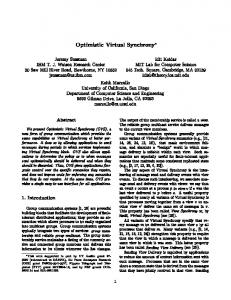
Structured Virtual Synchrony: Exploring the Bounds of Virtual Synchronous Group Communication Katherine Guo, Werner Vogels and Robbert van Renesse1 Dept. of Computer Science, Upson Hall, Cornell University, Ithaca, NY 14853, U.S.A. E-mail: {kguo, vogels, rvr}@cs.cornell.edu Multipoint communication protocols that offer group membership and virtually synchronous message delivery are commonly believed to be heavyweight and non-scalable. To meet the needs of large-scale computer-supported collaborative work, distributed parallel computing, and future worldwide applications, we designed the Structured Virtual Synchrony (SVS) protocol. The protocol has been implemented as part of Horus, a group communication system developed at Cornell University. It scales up to 800 members, while achieving a one-way latency of 100 milliseconds over groups of 500 members.
1 Introduction Applications such as distributed parallel computing and computer-supported collaborative work require reliable multipoint communication. A group-oriented approach has been successful in providing this support. One such approach is Virtual Synchrony (VS), also known as View Synchrony [1, 2, 3]. As the Internet grows, and large numbers of computers can collaborate to perform tasks, the use of the VS model in large groups and in worldwide applications is becoming more important. It is a common belief that VS protocols are heavyweight and nonscalable. How far can the protocols scale? What are the limits of their performance? These questions are answered in this paper through the analysis of the performance of the VS protocol and the introduction of a new hierarchical structure.
2 Virtual Synchrony in Horus Horus is an asynchronous group communication system based on a framework of highly modular protocol layers with a standard interface [9]. Applications build appropriate communication stacks from protocol layers at run-time avoiding unwanted functionality and costs. Each group is composed of endpoints where each endpoint has a communication stack. Every member of a group holds a private view of all currently connected members. Group membership changes are seen as a succession of views [8]. When there are no membership changes, a multicast is delivered to all members in the sender’s view. When there are membership changes, a new view is installed, and all multicast messages sent in the old view are delivered at surviving members before the new view is installed. This is the Virtually Synchrony model implemented in the VS layer in Horus. The core of the VS layer relies on the flush protocol. Any change in group membership will result in a designated coordinator multicasting a FLUSH message. After receiving this FLUSH message, all surviving members suspend message sending and return to the coordinator any messages from failed members that are not known to have been received everywhere. These messages are called unstable. After that, each surviving member sends the coordinator a FLUSH_OK message. Upon receiving all FLUSH_OK replies, the coordinator multicasts any unstable messages. After all messages become stable, the coordinator multicasts a VIEW message containing the list of endpoints that are currently in the group. The VS layer relies on reliable FIFO multicast and point-to-point communication, which is implemented in the NAK layer. Therefore an application that requires Virtual Synchrony only needs a stack “VS:NAK”. Experiments 1. This work was supported by the ARPA/ONR/DARPA grant N00014-96-1-1014. This paper appears in Proceedings of the 7th ACM SIGOPS European Workshop, Connemara, Ireland, September 9-11, 1996.
with the “VS:NAK” stack show that in a system of Sparc10’s, the maximum group size under high load is 40 with flush time and one-way latency reaching a high 460 milliseconds and 440 milliseconds respectively. Under normal circumstances, the flush time is on the order of 10 milliseconds, and the one-way latency is below 2 milliseconds. The NAK layer uses a mixture of a sliding window protocol and a negative acknowledgment protocol to offer reliable FIFO communication. A “status” report is multicast by each member every T1 = 2 seconds, or when a member receives a maximum allowed number of messages from any other member. This mechanism provides efficient discovery of lost messages and failure detection. In the VS layer, every member buffers all messages it has sent and received for possible retransmission. Only after a message becomes stable, i.e., it is known to have been received by all the members, can it be deleted from the buffers. If stability knowledge changes at a member, the member multicasts a “stability” report after at most T2 = 2 seconds. Consider the case where one member multicasts R messages per second in the group, and if no messages are lost, every other member receives R data messages per second. This problem by itself is scalable. When the application is built on top of the “VS:NAK” stack, background control messages are added to the system. Every 2 seconds, each member multicasts one NAK “status” report and one VS “stability” report. Thus each member receives n control messages every second where n is the group size. Since a receiver’s process speed and input buffer are finite, it can only process up to a certain number of input messages per unit time. When this limit is reached, as n increases, more messages are dropped, and therefore need be retransmitted, which adds load to the system. This snowball effect causes the VS protocol to break down after n = 40. This theory is supported by the observation that slower receiver processors drop more messages from the their input buffers than faster processors. Increasing T1 and T2 is a possible way to scale up, but there are trade-offs. Increasing T1 and T2 increases failure detection time and memory requirements respectively, neither of which is appropriate for many applications. The linear increase of both T1 and T2 causes a linear decrease of the number of background messages a member needs to handle per unit time. This results in a linear increase of the upper bound for a VS group. In order to achieve a better than linear increase in scalability, and keep both T1 and T2 unchanged, a new approach introduces a hierarchical structure into group management. This structure is suitable for large group sizes and for groups with members on geographically distant links.
3 Structured Virtual Synchrony A Structured Virtual Synchrony (SVS) group has a spanning tree structure in which members are divided into two categories: controllers and local members. Each controller manages a subset of the members which are its local members. Controllers interact with each other using the stack “VS:NAK”, forming the controller group. A controller interacts with its local members using the FIFO stack “NAK”, forming a separate local member group.
3.1 Message Passing and Message Ordering When multicasting a message, a controller begins within the controller group, and then each controller multicasts the message in its local member group. When a local member multicasts a message, it sends the message to its controller and the controller will pass it on as if itself is the sender. A similar approach is used in [1, 5]. Since the communication between a controller and its local members is FIFO, by adding an ordering layer (e.g., the Horus CAUSAL or TOTAL layer) on the controller group, the same property is offered to the entire SVS group. Although the SVS structure requires extra hops, retransmission requests are handled at controllers which may reduce the actual latency if local members are physically close to their controllers.
3.2 Stability Tracking Every member keeps all messages it has sent out and received. A local member sends acknowledgments only to its controller. After receiving a message m from controller j, controller i will not mark m as having been received until it has received acknowledgments from all of its local members. When a controller detects m’s stability in the controller group, it deletes m from the buffer. The controller multicasts this information in its local group, so its
local members can delete m too.
3.3 Membership Changes — the Flush Protocol The SVS flush protocol is an extension of the VS flush protocol presented in section 2. When there are membership changes, the coordinator of the controller group starts the flush by multicasting a FLUSH message in the controller group. After receiving a FLUSH message, a controller multicasts a FLUSH_LOCAL message in its local group. A member stops sending new messages upon receiving a FLUSH or FLUSH_LOCAL message. A local member sends unstable messages to its controller followed by a FLUSH_LOCAL_OK reply. After receiving FLUSH_LOCAL_OK messages from all of its local members, a controller sends a set of unstable messages followed by a FLUSH_OK message to the coordinator. This set is the union of unstable messages kept at the controller and returned by its local members. After all the messages become stable, the coordinator installs a new view in the controller group. As with a FLUSH message, once a controller receives a VIEW message from the coordinator, it multicasts it in its local group.
3.4 Choice of Local Groups There are other network transport protocols that use the concept of local groups. For example, the CP protocol and DSP protocol [7] generate local groups mainly based on addresses and the physical location of end systems. The SVS protocol is more flexible allowing users to dynamically construct local groups according to other metrics such as bandwidth, throughput, latency, error probability, and costs.
3.5 Scalability Bound Assume every member multicasts a NAK “status” report and a VS “stability” report every period T. In a VS group of size n, each member needs to handle 2n background report messages. In a SVS group of size n = p * q with controller group size being p and local group size q, every period T, every local member multicasts a “status” report, and a controller multicasts a “status” and a “stability” in the controller group and a “status” report in the local group. Therefore, the numbers of report messages each controller and local member need to handle are 2p + q and q respectively. Assume N is the maximum VS group size, then each member can handle at most 2N background report messages every period T. Therefore p and q must satisfy the following conditions: (a) q ≤ 2N and (b) 2p + q ≤ 2N. The maximum of n is achieved with p = N/2, q = N, and n = N2/2. In a system of Sparc10’s when T = 2 seconds, the upper bound for VS groups is N = 40, the upper bound for an SVS group is n = 800.
4 Performance The support for Structured Virtual Synchrony group is implemented in Horus as the SVS layer. The performance is tested on a system of SUN Sparc workstations consisting of Sparc10’s, Sparc5’s, and Sparc1’s connected by 10M bps Ethernet under normal load with UDP/IP multicast [4] as the transport protocol. We ran no more than three members per machine, and found the context switching effect to be negligible. The number of controllers stays at 16 as the SVS group size increases. Figure 1hows the average flush time when there are no unstable messages in the system. Figure 2 shows the average one-way latency when one controller multicasts rounds of small messages in the group. It is measured at the local members whose controller is not the sender. At n = 500, the flush time is 210 milliseconds and the one-way latency is 100 milliseconds.
5 Related Work In Transis [1], a similar structured approach is used in the VS protocol to improve its scalability. Processors on a LAN are clustered into a Broadcast Domain (BD). Each BD has a designated processor Xport. The Xports connect the BDs via point-to-point links into a Communication Domain (CD). VS is offered within a BD using an intra-BD protocol. The Xports run an inter-BD protocol to guarantee VS to the entire CD. Message stability tracking is done in the BDs and at the Xports. Assume the size of a CD is n = p * q, where p is the number of Xports, and q is the size of the BDs. Every period T, this scheme requires each Xport to handle 2p + 2q background control messages
and each BD member to handle 2q of them. As in the previous analysis, each member can handle at most 2N control messages, where N is the maximum size of an unstructured VS group, then (a) 2p + 2q ≤ 2N and (b) 2q ≤ 2N must be satisfied. The maximum of n is achieved when p = q = N/2, and n = N2/4 which is only 1/2 of the upper bound of the SVS group. In order to offer an ordering property like CAUSAL or TOTAL to a CD, the property needs to be offered within every BD and among the Xports. Whereas in SVS, it is only needed in the controller group, which makes SVS more scalable than Transis because of the lightweight NAK protocol used in local groups in SVS. RELACS [2] is a communication system designed for large-scale distributed systems. To handle large group sizes, different roles (core, client, sink) are assigned to each member, and different semantics are offered to different types of members. For groups with large geographic separation, membership partition is handled. Horus provides similar flexibility, and can achieve large scalability by reducing semantics.
6 Conclusion Experience with the Structured Virtual Synchrony (SVS) group shows that virtual synchrony can be made scalable by incorporating hierarchy into group management protocols. This approach has increased the scalability dramatically from 40 to 800 without reducing group semantics. The scalability comes from (a) reducing background control traffic, (b) parallel processing data acknowledgments and FLUSH_LOCAL_OK replies and (c) locally handling retransmission requests at controllers. The concept of local groups in large group multicasting protocols is general enough that it can be applied to increase the scalability of protocols [5, 6, 7] with weaker semantics than VS. To further increase the scalability, a multi-level tree can be constructed. To minimize the number of hops a message needs to go through, the message sending algorithm can be modified to use the underlying IP multicast directly instead of going through the SVS structure. We are currently in the process of simulating this to see how well this works. The scalability problem in group communication comes in two flavors: one is to handle a large group, another is to handle a group spanning large geographic areas. The hierarchical group structure used in SVS protocol addresses both problems.
Acknowledgments We would like to thank Andrew Feng, Mark Hayden and Alexey Vaysburd for their many helpful discussions and review of this paper. 500 450 400
flush time (msecs)
350 300
VS group
250 SVS group
200 150 100 50 0 0
50
100
150
200
250 300 group size
350
400
450
Fig 1: Flush time for SVS and VS groups.
500
References [1]
Y. Amir, D. Dolev, S. Kramer and D. Malki. Transis: A Communication Sub-System for High-Availability. In Digest of Papers, The 22nd International Symposium on Fault-Tolerant Computing Systems, pages 76-84. IEEE, 1992.
[2]
O. Babaoglu and A. Schiper. On Group Communication in Large-Scale Distributed Systems. In Proceedings of ACM SIGOPS European Workshop, Dagstuhl, Germany, September, 1994
[3]
K. P. Birman. The Process Group Approach to Reliable Distributed Computing. Communications of the ACM, Vol. 36, No. 12, pages 37-53, December 1993.
[4]
S. Deering. Host Extension for IP Multicast. RFC 1112, August 1989.
[5]
M. Hofmann, T. Braun and G. Carle. Multicast Communication in Large-Scale Networks. Third IEEE Workshop on Architecture and Implementation of High Performance Communication Subsystems. pages 147-150, 1995.
[6]
M. G. W. Jones, S. Sorensen and S. R. Wilbur. Protocol Design for Large Group Multicasting: the Message Distribution Protocol. Computer Communications, Vol. 14, No. 5, pages 287-297, June 1991.
[7]
S. Paul, K. Sabnani and D. Kristol. Multicast Transport Protocols for High Speed Networks. In Proceedings of International Conference on Network Protocols, Boston, October 1994
[8]
R. van Renesse, K. P. Birman, B. Glade, K. Guo, M. Hayden, T. M. Hickey, D. Malki, A. Vaysburd and W. Vogels. Horus: A Flexible Group Communication Subsystem. Technical Report TR 95-1500, Cornell University, Ithaca, NY, 1995.
[9]
R. van Renesse, K. P. Birman, R. Friedman, M. Hayden and D. A. Karr. A Framework for Protocol Composition in Horus. In Proceedings of the Fourteenth Annual ACM Symposium on Principles of Distributed Computing, pages 80-89, Ottawa, Ontario, August, 1995. ACM SIGACT-SIGOPS.
450 400
one−way latency (msecs)
350 300 250 200
VS group
150 SVS group
100 50 0 0
50
100
150
200
250 300 group size
350
400
450
Fig 2: One-way latency for SVS and VS groups.
500