Process Landscaping by developing a real-world software process. ... contain processes starting immediately after first contact to the customers and living.
Structuring Complex Software Processes by „Process Landscaping“ Volker Gruhn, Ursula Wellen University of Dortmund, Department of Computer Science, Software Technology, 44227 Dortmund, Germany {gruhn,wellen}@ls10.cs.uni-dortmund.de
Abstract. Process Landscaping is a method, which supports modelling of related processes. These processes can be modelled on different levels of abstraction. Interfaces between processes are considered as first class process entities. It prevents loosing an overview of the whole framework of processes and ensures that decisions about processes are not burdened out by an overwhelming amount of details. In this article we discuss the approach of Process Landscaping by developing a real-world software process.
1
Introduction
Modelling of software processes can have various purposes like documentation, analysis and improvement of software process models [Gru92, BFG93, CW95], software process improvement [ABC96, BJ95, SNT98] and software process execution [DG98, EAD99]. Independent of the concrete purpose most process modelling projects have to identify the core processes and define their chronological order of modelling. Furthermore, they have to identify and specify the interfaces between processes. To ensure that the overall context of process modelling does not get lost one should concentrate on a small number of core software processes and distinguish between processes with and without direct interfaces to customers (internal and external processes) [HC93]. It becomes obvious that interfaces have to be modeled already on an abstract level (that means at the very beginning of a modeling project) when a number of processes has to be modeled and when the involved process modellers cannot easily identify how these processes are related. Additionally, the lack of manager‘s understanding of the purpose and benefits of process modelling sometimes requires modelling processes on different levels of detail. It is important to abstract from details of certain processes or even from certain processes as a whole to keep in view the whole process framework. The salient features of the method of „Software Process Landscaping“ are • identification of the core software processes and their positioning on a top level view of a process landscape, • explicit modelling of interfaces between software processes, • switching between different levels of refinement,
• extension by process model details only where needed. Especially the second feature differentiates process landscaping from other process modelling methods like those based on event-driven process chains [MS96], Petri Net-like languages and data flow diagrams, where interfaces are not first class entities. Therefore corresponding software process modelling tools do not provide mechanisms for checking interface consistencies. In section 2 we discuss the process landscaping method in terms of key activities carried out. In section 3, the development of a real software process landscape is discussed. Section 4 sums up our experiences with applying process landscaping to real world software processes and gives an overview of our future research directions.
2
The Process Landcaping Method
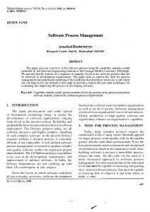
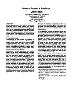
A process landscape describes how software process models are related. Figure 1 gives a schema of a process landscape on the most abstract level. On this level, we do not identify individual process models, but we deal with clusters of process models which are logically related (for example, because all of them describe processes from the area of configuration management). The clusters are related by cluster interfaces represented on this level by two-headed arrows. To each of these clusters the method of process landscaping can be applied again. Based on refinements of this kind, we start from high level descriptions. We can add details about all entities of process models (like activities, object types, tools, etc.) wherever needed.
direction of modelling
customer life cycle
Cluster B Cluster C
Cluster A
Cluster D
customer processes
supporting processes
Fig. 1. Schema of a process landscape We put a process landscape into a system of coordinates. The x-axis ranges from processes with direct interfaces to customers (called customer processes in the following) to supporting processes. The y-axis describes the dimension of the customer life cycle. It starts when a customer comes into life and terminates when the
customer relationship terminates. The term “customer” is used in a rather general sense here; the “customer” of a software house is somebody who purchases software, the customer of an internal software development department is the software user. At least one of the processes identified in a process landscape is supposed to be a customer process, otherwise all activities of all processes are exclusively devoted to internal work without any impact on the real world. Each customer process may depend on an arbitrary set of supporting processes. Each of these may itself depend on other supporting processes. The further away from an interface to the customer, the further to the right on the x-axis the process is allocated. The later in the customer life cycle the further up (on the y-axis) the process is allocated. Process clusters which contain processes starting immediately after first contact to the customers and living until the end of the customer life cycle are identified as background processes. They are depicted as clusters on the bottom of a process landscape (compare process model cluster “Project Management” in figure 2). The allocation of process model clusters in a process landscape is not meant to convey a formal notion of when to start with a process model cluster and when to terminate it. It is supposed to illustrate the context in which processes take place. All details needed to understand when to start and terminate processes are given on the lower level of process models. Based on these simple agreements, the process landscape immediately shows how processes are related and which role they play in the concert of all processes of a software company. According to the two dimensions of distance to customers and customer life cycle, there is a natural direction of process modeling. It starts with processes which deal with new customers arriving. Processes which directly support these processes and customer processes which are carried out next are modelled afterwards. This modelling direction ensures that details about other processes (e.g. from the upper right corner of our landscape) are not described, unless it is obvious that they are actually needed. Without a clear modelling direction there is the danger to start modelling in a rather unfocused way. The results could be fragments of process models which do not fit and which perhaps are not needed. Thus, process landscaping does not only serve as an important means for orientation during modelling, but it also helps to spend modelling effort in a focused and goal-oriented way. Process landscaping contains the following steps: 1. 2. 3. 4. 5.
Identification of process model clusters Identification and description of interfaces between clusters Refinement of clusters Acquisition of knowledge about processes Process model release and change control
These steps are discussed in the following section in more detail. They are explained along an example of a software development process.
3
Developing a Software Process Landscape
In this section we discuss the development of a software process landscape which covers all processes concerning a complex software development project. In this example we use FUNSOFT nets [GU98] (high level Petri nets), but we could use any other modeling languages which supports the definition of interfaces between processes as for example SLANG [BFG93], SOCCA [EG94], Little-JIL [SOS98]. For this article it is sufficient to know that we use Petri nets; it is not necessary to know any details about FUNSOFT nets. Following the direction of modeling of the process landscaping method, we start the development of the software process landscape with processes concerning the preparation of a project plan. Then we continue with starting the software development activities. In parallel to software development activities, several quality management tasks have to be carried out. When the first software components are released, configuration management can start. Subsections 3.1 to 3.5 explain the different steps during the development of a software process landscape, each illustrated by an example. 3.1
Identification of Process Model Clusters
We identify process model clusters by interviewing those persons who either consider themselves as process owners for specific processes or who are claimed to be process owners by executive managers. Talking to these people usually gives a quick impression about the core processes to be considered. Of course, this quick and immature impression is not definitive, but it serves as a good starting point. If a refinement or a summary of a cluster seems to be necessary at a certain time, this can be done easily (see section 3.3). The customer life cycle oriented approach taken in process landscaping results in the following process model clusters: • • • •
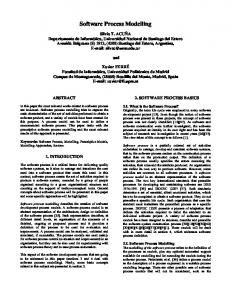
Project Management Software Development Quality Management Configuration Management Configuration Management
customer life cycle
Software Development
Quality Management
Project Management customer processes
supporting processes
Fig. 2. Software Process Landscape Figure 2 shows the top-level representation of the software process landscape. We start with the overall cluster “Project Management” because it contains processes very closely related to a future user as well as background processes of the software house. This cluster also affects the whole customer life cycle. In the graphical representation we find it in the bottom part ranging over the complete x-axis. To receive and to check the order to develop a software system is one of the processes of this cluster. When the order is received, the development of the software system can start. Once the requirements for a software system are identified, the processes from the area of quality management and further project management processes become active. These are processes which do not deal with users directly. When the system design has been defined and some software components are implemented, configuration management processes become more and more important. Configuration units have to be identified and a release plan has to be developed. Installation checks have to be carried out in co-operation with the quality management and at least the system delivery has to be prepared. The delivery process itself is again a process closely related to the user (within the cluster “Configuration Management”). The two-headed arrows already depict some cluster interfaces which exist obviously. The way how to identify them all and how to describe them will be discussed in the following section. 3.2
Identification and Description of Interfaces between Clusters
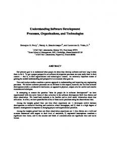
Two clusters are connected if there is at least one information exchange between processes of both clusters (compare to the notion of an interface refinement illustrated in figure 3). Key interfaces between clusters become obvious in the same way as clusters do, simply by asking people to tell the types of information which are exchanged. On the most abstract level the purpose of cluster interfaces is just to indicate that both clusters contain process models which share at least one interface. For a more detailed description we use circles (called channels), named like the type of data which has to be exchanged. Directed edges indicate from where to where information is exchanged. Figure 3 shows an example of an interface agreement between two process model clusters, namely between cluster “Software Development” and cluster “Quality Management”. It shows that there are six channels between these two clusters and it shows which types of data are passed from one cluster to another. The example shows that some guidelines for development activities are passed from quality management processes to software development processes and that results are returned. The programming guidelines and the specification guidelines are mentioned explicitly, other types of guidelines are omitted in figure 3. Single-headed arrows denote the
flow of information between clusters. Sometimes pairs of channels are used to show the type of information which is passed into one direction, processed in the destination cluster and returned back. For example, the software code which has to be tested (see figure 3, interface B) is sent back from cluster “Quality Management” to cluster “Software Development” through channel C (tested software code) when it has been tested.
Fig. 3. Refined interfaces between process model clusters “Software Development” and “Quality Management”
3.3
Refinement of Clusters
After the identification of the core processes the concerning clusters have to be refined. To get a more detailed knowledge about the internal structure of each cluster we need a complete list of all activities belonging to such a cluster. These activities either can be so coarse-grained that they are described as a cluster (which itself needs further refinement) or they can be so fine-grained, that they can immediately be described by a process model. Figure 4 illustrates the relationhip between the refinement of a core process and its mapping on the several levels of the software process landscape. Each core process is described as a set of process models either directly or after one ore more subclustering steps.
Fig. 4. Relationship between core process and cluster, activities and process models If we apply the way of refining a cluster to our software development example, the cluster “Software Development” can first be devided into five subclusters, namely • • • • •
Requirement Definition Requirement Analysis Software Specification System Design Implementation
Figure 5 shows this refinement together with interfaces to cluster “Quality Management” and cluster “Configuration Management”. While the interfaces to cluster “Configuration Management” are not refined, single-headed bold arrows show how interfaces between cluster “Software Development” and cluster “Quality Management” are used in the refinement of cluster “Software Development”. They are connected with subclusters of cluster “Software Development”. This shows how interface refinements and cluster refinements are composed. The subclusters of cluster “Software Development” also have interfaces between each other. They are indicated as two-headed arrows in figure 5 and can be refined in a further step.
Fig. 5. Subclusters of cluster “Software Development” with refined interfaces to cluster “Quality Management” and interfaces to cluster “Configuration Management” The cluster “Project Management” is refined directly to a set of process models (see figure 6), namely “prepare project plan”, “review project plan”, “cost control”, “post mortem analysis”. Each of these process models is then described by means of a software process modelling language, in our example by FUNSOFT nets (not depicted here).
Fig. 6. Process models within the cluster “Project Management”
3.4
Acquisition of Knowledge about Processes
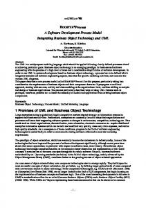
Knowledge acquisition starts with interviews and with careful reading of available documentation. To obtain more detailed information about processes, we deploy process scenarios dealing with customers with different perspectives and objectives. A scenario describes a typical process situation and identifies processes used to cope with this situation. Scenarios start from high level descriptions. A process owner and a process modeler use a scenario for a step-by-step walkthrough. For each activity, details are added (which exceptions may occur, what is the type of input information needed and of output information produced, who is responsible, which tools are used, which guidelines are to be applied). The result is a detailed process model which can be refined in the same way. In our example we did knowledge acquisition for one process model out of the cluster “Configuration Management”. This cluster has been refined by a set of process models directly. The process models used the FUNSOFT net semantic as basis. Figures 7a and 7b represent the process model “Release System” which belongs to the cluster “Configuration Management”. Figure 7a shows the complete process model, whereas figure 7b illustrates a refinement of the activity “release” within the process model “Release System”. The arrows within the two FUNSOFT nets indicate data and control flow.
Fig. 7a. Process model “Release System” of cluster“Configuration Management” When a release request comes in, the activity “release” needs information about the configuration units relevant for a new release. This information will be sent via a process model interface of the cluster “Quality Management” depicted as channel“c. units relevant for release” (see also figure 4, interface C). The activity “release” itself consists of several tasks like the identification of configuration units to be exchanged and the adaptation of altered configuration units (compare to figure 7b). As results of the release activity we get the released system, detailed configuration information and release notes (see channels in figure 7a, 7b). After the integration of all exchanged and adapted configuration units the configuration will be under control of the configuration manager. He can now deliver the released system to the user. This fact is illustrated as activity “control configuration” and the outgoing channel “released system to the user”.
Fig. 7b. Refinement of activity “release within the process model “Release System” of cluster“Configuration Management”
3.5
Process Model Release and Change Control
Once stable process models have been obtained, they have to be released and “change-managed”. This means, that the process model is made available to all people interested and that from then on change requests are handled in a formal way. Internal details of a process model are checked by the process owner. If he/she decides that everything is properly modelled, then one precondition for a model release is satisfied. The other precondition is that changes of process interfaces have to be agreed on by all owners of processes using these interfaces. The mechanism for doing so is a common meeting with the owner of the process whose model is about to be released and with the owners of all other processes with interfaces to the model which is to be released. These meetings are moderated by the process owner of the process model concerned. The goal of such a meeting is to present process details (in order to raise understanding for the structure of the process) and to finally agree on interfaces. Once this is done, new versions of process models can be released.
3.6
Process Model Release and Change Control
Figure 8 depicts the software process landscape as it was developed in the previous subsections. It doesn’t depict the complete landscape because this would go beyond the limits of the figure. The overall view is just to get a feeling of how a complete landscape could look like and how different representations on different levels of abstractions are related.
Fig. 8. Overall view of the software process landscape In the center of the overall landscape we find the most abstract clusters representing the core processes. They are arranged into a system of coordinates as it was introduced in section 2, figure 1 (see bold lines in figure 8). All refinements of either a cluster, an interface or a process model activity are indicated by two broken lines leading from the abstract entity to its refinement.
Starting from the very top of the landscape we refine the clusters by subclusters, and/or process models. The cluster “Software Development” is refined into five subclusters (left side of figure 8). Their interfaces to each other are depicted as twoheaded arrows analog to the most abstract level of the landscape. The overall cluster “Project Management” is refined into four process models without subclustering previously (right side of figure 8). The cluster “Configuration Management” is refined into subclusters neither. One of its process models, namely the process model “Release System”, is depicted as a FUNSOFT net (see also figure 7a). This type of Petri nets enables further hierarchical refinement of process model activities. The activity “release”, depicted as rectangular symbol, is refined this way (see also figure 7b). Figure 8 also shows a refinement of the interface between the two clusters “Software Development” and “Quality Management” (see bottom of figure 8, see also figure 3). The list of the objects to be exchanged is not complete, but it shows how the two-headed arrows, indicating the data flow relation, has been refined to one-headed arrows. For cluster “Project Management” it is indicated that details are given by four process models, called ”prepare project plan”, “review project plan”, “cost control”, “post mortem analysis”. These process models are described by FUNSOFT nets in the next step. In figure 8 we omitted some details about the composition of refinements, because the composition rules have already been illustrated in the previous subsections. Figure 8 might appear overly complicated, but the different notions of refinement turned out to be useful in structuring complex software processes. Obviously, it is not reasonable to apply all kinds of refinement in a small example (as given in figure 8). This example is only meant to illustrate the interplay of the different notions of refinement.
4
Conclusion
We applied the method of Process Landscaping to software processes in various telecommunication and insurance companies as well as in software houses. The experiences we made in modelling software processes show this method is useful in most cases. Only small modelling projects could be handled in a more efficient way without Process Landscaping. There are two particular strengths of Process Landscaping: One is the focused modelling of core processes where information details are only modelled, when there are relevant. Otherwise their depiction will be avoided. The other one is the communication support on different levels of abstraction. The top level view of a process landscape is useful to discuss with managers, details can be discussed on lower landscape levels with software developers. In its current state, process landscaping supports checking of predefined consistency conditions. Our future research with respect to consistency conditions will be focused on user-defined consistency conditions and support for their automatic evaluation. Our future work will also be focused on the integration of process
modelling tools into the process landscaping method. This will ensure us to avoid unnecessary re-implementation of process modelling tools and it will easily allow to benefit from process landscaping in projects which already fixed a particular software process modelling language and/or tool.
References [ABC96] D. Avrilionis, N. Belkhatir, P.-Y Cunin, Improving Software Process Modelling and Enactment Techniques, In: C. Montangero (ed.), Software Process Technology – Proceedings of the 5th European Workshop, Nancy, France, Oct. 1996, appeared as Lecture Notes in Computer Science No. 1149, pages 65-74 [BFG93] S. Bandinelli, A. Fugetta, S. Grigolli, Process Modelling in-the Large with SLANG, In:Proceedings of the 2nd International Conferenceon the Software Process – Continous Software Improvement, Berlin, Germany, Feb. 1993, pages 75-83 [BJ95] J.G. Brodman and D.L. Johnson, Return on Investment (ROI) from Software Process Improvement Measured by US Industry, In: Software Process Improvement Practice, John Wiley and Sons, Pilot Issue, Volume 1, August 1995, pages 35-48 [CW95] J.E. Cook, A. Wolf, Automating Process Discovery through Event-Data Analysis, In: Proceedings of the 17th International Conference on Software Engineering, Seattle, Washington, US, 1995, pages 73-82 [DG98] W. Deiters, V. Gruhn, Process Management in Practice - Applying the FUNSOFT Net Approach to Large Scale Processes, In: Special Issue on Process Technology / Automated Software Engineering, Nr. 5, 1998, pages7-25 [EAD99] J. Estublier, M. Amiour, S. Dami, Building a Federation of Process Support Systems, In: Proceedings of the International Joint Conference on Work Activities and Collaboration WACC ’99, San Francisco, California, Feb. 1999, pages 197-206 [EG94] G. Engels, L. Groenewegen, SOCCA: Specifications of Coordinated and Cooperative Activities, In: A. Finkelstein, J. Kramer, B. Nuseibeh (eds.), Software Process Modelling and Technology, John Wiley & Sons, London, England, 1994, pages 71-100 [Gru92] V. Gruhn, Software Process Simulation on Arbitrary Levels of Abstraction, In: A. Sydow (ed.), Computational Systems Analysis 1992, Elsevier, Amsterdam, Netherlands, 1992, pages 439-444 [GU98] V. Gruhn, Urbainczyk, Software Process Modeling and Enactment: An Experinece Report Related to Problem Tracking in an Industrial Project, In: Proceedings of the 20th International Conference on Software Engineering, Kyoto, Japan, Apr. 1998, pages 13-21 [HC93] M. Hammer, J. Champy, Reengineering the Corporation, Harper Business, New York, US, 1993 [MS96] S. Meinhard, F. Sänger, R/3 Deveolopment Processes as Framework for Successful Projects (in German), HMD 33 (192), 1996, pages 100-112 [SNT98] K. Sakamoto, K. Najakoji, Y. Takagi, N. Niihara, Toward Computational Support for Software Process Improvement Activities, In: Proceedings of the 20th International Conference on Software Engineering, Kyoto, Japan, April, 1998, pages 22-32 [SOS98] B. Staudt Lerner, L.J. Osterweil, S.M. Sutton Jr., A. Wise, Programming Process Coordination in Little-JIL, In: V. Gruhn (ed.), 6th European Workshop on Process Technology, Weybridge, UK, Springer, Heidelberg, Germany, 1998, appeared as Lecture Notes in Computer Science No, 1487, pages 127-131