involves the successive elaboration of controller re- sponses and details of the equipment under control. A re nement C of a system A must be able to respond.
Structuring Reactive Systems in B AMN K. Lano
K. Androutsopoulos
P. Kan
Department of Computer Science, King's College London, Strand, London WC2R 2LS
Abstract B has been widely used for high-integrity system development, for example in the railway industry. However there are few published guidelines on how to structure B speci cations for particular types of system, such as reactive control systems. In this paper we describe a method to support graphical design of systems using B AMN, and develop guidelines for expressing the structuring requirements of reactive systems in B.
1 Introduction Reactive systems can usually be characterised as transformations from sequences or sets of input signals into sequences of output signals. Their function is to respond to input signals from sensors by sending commands to actuator devices, in such a way that required invariants of safety and operational behaviour remain true for the controlled system. A development process for reactive systems should be repeatable in the sense that given any sets S of sensor components, A of actuators, and I of operational and safety invariants, the procedure can be applied to provide a set of control algorithms and a design structure connecting these algorithms to each other and to the sensors S and actuators A, in such a way that I is satis ed. In our method, RSDS, reactive control systems are partitioned in such a way that the development procedure can be applied to the subparts of the system in the same way as it is applied to the entire system. That is, a subpart can be regarded as a self-contained reactive system whose `sensors' include both sensors of the original system and `virtual sensors' which serve to transmit necessary information from other parts of the original system. Its actuators in turn will include both actuators of the original system, and outputs to other subparts of this system. It will also have its own safety and operational properties, derived from those of the original system.
The partitioning strategy chosen is described in Section 2, which de nes our graphical notation, SRS statecharts, for reactive systems, and in Section 3, which describes the overall development process for our approach, RSDS. Section 4 describes the synthesis process for deriving controllers from invariants. Section 5 identi es how structuring in B can be used to implement reactive system structuring requirements. Section 6 illustrates the development procedure on a case study of a fault-tolerant production cell. Section 7 addresses the issue of event ordering by the outer level of a control system.
2 Structured Reactive System (SRS) Statechart Notation SRS [13] is designed to be a modular subset of statechart notation, compatible with B AMN. A transition in an SRS statechart has a label of form t : e [G ]=e1 a : : : a en where t is an (optional) transition name, e the name of the event triggering t , G is a logical guard condition, and the ei are the events generated by t . G is a logical combination of tests in s where s is a state of the statechart, G is optional and defaults to true . The ei are also optional. None of the ei can lead directly or indirectly to a generation of e . A formal de nition of SRS is given in [13].
State machines Restricted statecharts are de ned in terms of state machines. Formally, a state machine A consists of sets StatesA of states, EventsA of events and TransA of transitions. Each transition t of A has a source state sourceA (t ) StatesA , a target state targetA (t ) StatesA , and an event eventA (t ) EventsA which denotes the event which may trigger the transition. There is a designated initial state initA . It is denoted as the target of a virtual transition arrow which has no source. 2
2
2
State machine abstraction morphisms and re nements Stepwise re nement of reactive systems
involves the successive elaboration of controller responses and details of the equipment under control. A re nement C of a system A must be able to respond to all requests that A can, in a compatible way. This is formalised by the concept of an abstraction morphism. A state machine abstraction morphism � : C A is a function from StatesC EventsC TransC to StatesA EventsA TransA which maps each state s of C to a state �(s ) of A, each event � of C to an event �(�) of A, and each transition t of C to a transition �(t ) of A, such that: 1. If the event of t in C is �, then the event of �(t ) in A is �(�): eventA (�(t )) = �(eventC (t )). 2. sourceA (�(t )) = �(sourceC (t )) and targetA (�(t )) = �(targetC (t )). 3. �(initC ) = initA . Such a morphism preserves the behaviour of a state machine in the sense that all transitions t : s s 0 in C for a given event � must correspond to some abstract transition �(t ) : �(s ) �(s 0 ) in A for the same event. That is, no essentially new behaviour can be introduced for �. C is a re nement of A via � if � is a state machine abstraction morphism which is an isomorphism on the set of events of C and A. A re nement � is adequate if every state s of A has some corresponding state of C : !
[
[
[
[
!
!
8
s : StatesA � 9 s 0 : StatesC � �(s 0 ) = s
and if every event � which has an abstract transition from some s also has a corresponding concrete transition from each corresponding state: 8
s : StatesA; t : TransA � eventA (t ) = � ^ sourceA (t ) = s ) (8 s 0 : StatesC � �(s 0 ) = s ) 0 9 t : TransC � �(eventC (t 0 )) = � ^ �(t 0 ) = t ^ sourceC (t 0 ) = s 0 )
This ensures that C can react to � in every situation that A can. By de nition of re nement, the e�ect of this reaction is also consistent with that given in A. The adequacy condition is similar to the \preservation of precondition" requirement of Z re nement [7].
OR and AND composition SRS statecharts are de ned as for state machines, with the additions of the two constructions of nesting of statecharts within states (OR composition) and concurrent (AND) composition.
In the SRS formalism, these constructs can be eliminated successively (` attened') to reduce a statechart S to a state machine atten (S ). Abstraction and re nement morphisms are de ned for SRS statecharts in such a way that they produce state machine abstraction and re nement morphisms on the attened state machines [12]. This enables us to avoid explicit attening and instead work with structured statecharts and morphisms de ned between these.
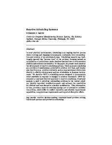
Modules and subsystems In SRS statecharts all systems are described in terms of modules: an OR state containing only basic and OR states. A system description S is speci ed by the AND composition M1 : : : Mm of all the modules contained in it, modules (S ) = M1 ; : : : ; Mm . Such an S is termed a module system. Each module M in S has a set receiversS (M ) of modules in S , which are the only modules of S to which it can send events. receiversS is acyclic: M receiversS� [ M ] where receiversS� is the transitive closure of receiversS considered as a relation. Additional constraints may be placed on the form of receiversS , for example, requiring that it is a tree: no two modules have a common receiver. This corresponds to the purely hierarchical structure of subsystems within a B development [16]. Typically modules in a module system represent sensors, controllers, subcontrollers, and actuators. Figure 1 shows the typical arrangement of subsystem modules for a reactive system, and the associated hierarchy of modules under the receivers relation. Subcontroller 1 and Subcontroller 2 are the receivers of Controller , etc, Actuator 3 has transitions for g 1 and g 2. Each module is a separate OR state within an overall AND state representing the complete subsystem. j
j
f
g
62
Controller
Sub Controller 1
Sub Controller 2
e/f
Actuator 1 Actuator 2
f
g
Controller Sub Controller 1
Sub Controller 2
f/g1^g2 Actuator 3
Actuator 1
Actuator 2
Actuator 3
Figure 1. Typical subsystem structure
3 Development Method In the RSDS (Reactive System Design Support) method reactive control systems are represented using DCFD notation (eg: Figure 2). The behaviour of sensors, controllers and actuators is speci ed using SRS modules in the notation of Section 2. Initially only sensors and actuators have ex-
Sensors
Actuators
output commands input events
Controller
Figure 2. Structure of Reactive Control Systems
plicit state machine/module representations, and the speci cation of the mediating controller(s) is implicit in a system invariant P in terms of sensor and actuator states. The form of P can be used to guide the decomposition of the controllers and to synthesise control actions, as described in [12]. Invariants of SRS modules are expressed in the following language. Let S consist of modules M1 , : : :, Mn where some of these modules describe the behaviour of sensors, others of controllers and others of actuators. For each module M a variable m state is de ned, of type States atten (M ) (ie, the basic states of M ), and formulae based on equalities m state = s1 are used to express the current state of module M . Except for the most trivial systems, it is necessary to modularise the speci cation of the control algorithm, in order to obtain analysable descriptions. There are several ways in which such a decomposition can be achieved: 1. Hierarchical composition of controllers: events e are dealt with rst by an overseer controller S which handles certain interactions between components, and e (or derived events) are then sent to subordinate controllers responsible for managing the individual behaviour of subcomponents. 2. Horizontal composition of controllers: events are copied to two separate control algorithms S1 and S2 , which compute their reactions independently. 3. Decomposition by control mode: A separate controller is speci ed for the control reactions to be carried out in each mode or phase of the system [9]. The rst two are based on the physical decomposition of the actual system, whilst the third is based on temporal decomposition.
Invariants of controllers are decomposed into invariants of subcontrollers when the controller is structurally decomposed [12], as follows: 1. Hierarchical composition: If this is based on splitting the actuators into disjoint sets A1 , : : :, An which are controlled by separate subcontrollers C1 , : : :, Cn of a supervisor controller C , then the invariants which only refer to actuator states from Ai are placed in Ci , invariants which link actuators from di�erent Ai sets are placed in C . 2. Horizontal composition: Same as hierarchical, except that all invariants will be placed in one or other subcontroller, with none in the coordinator C. 3. Phase decomposition: The invariant P of C will be split up into disjoint cases P1 , : : :, Pn such that P
�
P1 _ : : : _ P n
Each of the Pi becomes the invariant of a subcontroller Ci for that phase. In the case that the phases are distinguished by the value of a variable sstate for a particular sensor, ie, Pi
�
(sstate = vi Qi ) ^
for each i : 1 : : n , then P is equivalent to (sstate = v1 (sstate = vn
) )
Q1 ) ^ : : : ^ Qn )
(assuming that vi = vj if i = j and these are the only possible values of sstate ). The invariant of Ci can then be simpli ed to Qi . 6
6
In each case the original control system design and synthesis task is reduced to a set of simpler synthesis and design tasks. When a controller cannot be decomposed further, the synthesis process of the following section is applied to derive an SRS module or B machine to implement its behaviour.
4 Controller Synthesis The interactive synthesis procedure supported by the RSDS tool prompts the designer to select suitable invariant clauses to be used in de ning and checking proposed reactions to each event that may be input to the system [12]. The use of abstractions of subcontroller states and abstraction morphisms to these abstractions can help
reduce the state space that needs to be considered during synthesis. E.g. for the press controller of Section 6 there are only 7 high level states, instead of approximately 9000 possible concrete states. If the SRS description has a tree structured receivers relation, then the SRS structuring can be mapped directly to a corresponding structure in B: if module D is in receivers (C ), then the machine C 0 for C INCLUDES the machine D 0 for D . However in cases such as a temporal decomposition of controllers, typically some modules (representing actuators used in more than one phase) will be in the receivers sets of two di�erent controllers, a structure which is disallowed in B because of the additional complexity of proof needed.
� =
ms ms ? m VAL VAR; ms = sr1 ^ G1 m STO VAR(tr1 ); act
VAR IN IF THEN ELSE END END;
0
:::
. . . END
4.1 Translation from SRS to B AMN
where act 0 = 1 ; : : : ; m . The following theorem shows that re nement of control algorithms can either be carried out within the SRS notation or within B AMN, depending on the preferences of the developer or the requirements of standards.
For a state machine M , the corresponding B abstract machine is (M ) de ned as:
Theorem If M 0 and M are statemachines, and M 0 is
B
M N Nu m state m state : StateM ^ InvM m state := initM
MACHINE INCLUDES 1; : : : ; VARIABLES INVARIANT INITIALISATION OPERATIONS � PRE THEN IF THEN ELSE : : : END END;
=
an adequate re nement of M via �, then the translation of M 0 to a B machine (M 0) re nes the translation (M ) of M . B
B
5 Structuring Requirements for Reactive Systems
m state : f sr1 ; : : : ; srn g m state = sr1 ^ G1 m state := tr1 jj act
. . . END
where InvM is the conjunction of operational and safety invariants attached to M . An operation of the above form is included for each event � EventsM , where 2
t ; : : : ; tn g = ft : TransM j eventM (t ) = �g
Several kinds of structuring are typically required for the speci cation and design of a reactive system: command-recipient structures, with sharing (for example where two controllers both send commands to the same actuator) or without, and aggregation or collection structures (eg, where there are several instances of a particular controller or actuator in the system, with isomorphic structure). Additionally certain forms of re exive or cyclic module dependency structures are needed, in cases where components combine the roles of a sensor and an actuator. We will identify how these structures can be expressed in B in the following sections.
f 1
5.1 Shared Command-Recipient Structures
and ti has source sri , guard Gi , generations 1 a: : :a m and target tri . The Ni are the machines corresponding to the elements of receivers (M ). act is 1 : : : m . The implementation of this machine is generated along with the speci cation by the RSDS tool: jj
M 1 M m Vvar (StateM ); N1 ; : : : ; Nu m state = m Vvar m STO VAR(initM )
IMPLEMENTATION REFINES IMPORTS INVARIANT INITIALISATION OPERATIONS
jj
Although the purely hierarchical structure of treestructured SRS speci cations can be mapped directly into a corresponding INCLUDES structure (at the B speci cation level) and IMPORTS (at the B implementation level), other forms of structure such as DAGs (directed acyclic graphs) cannot be generally translated. This di�culty arises with phase decomposition in particular, in which controllers C1 and C2 for di�erent phases may both need to send commands to the same actuator A. In B this would mean that the machines
(C1 ) and (C2 ) both INCLUDE (A), which is an invalid structure. Such `shared include' structures are excluded in B because if M and N both include a machine S , then the operations of M may break the invariant of N by modifying the data of S , and likewise the invariant of M can be violated by operations of N . In the case of phase decomposition there is no actual danger of inconsistency because all phase controllers are included in an overseer controller which responds to events by forwarding the event to the controller for the currently active phase. In the simple case, there are two phases, distinguished by the value of some sensor variable (swstate in the train control case study [12]) or an additional variable pstate giving the current phase. In this case the separate phases have invariants P1 and P2 , say, and the supervisor controller has an invariant I :
B
B
B
(pstate = p 1 P1 ) (pstate = p 2 P2 ) The operations of the supervisor all have the form )
^
)
e =
pstate = p 1 p1 e p2 e
IF THEN ELSE END
where p 1 e is an operation of the rst phase controller, and p 2 e of the second. Then the invariant I is maintained by e because I
)
(pstate = p 1 (pstate = p 2
) )
[p 1 e ]I ) [p 2 e ]I )
of one phase controller will not preserve the invariant of the other. For example in the train control system of [12], the phase controller SwOn has the invariant dstate : closing ; closed ; locked , whilst SwO� has an operation f
swo� dbpressed = IF motstate = stationary THEN start open doors END
which breaks this invariant. Instead, the approach of [3] can be used, with a machine K which EXTENDS two machines N and M which share by INCLUDES a machine S being expressed as K = N �M 5.2 Aggregate and Collection Structures
If a system contains several copies of a component, such as the press in the fault-tolerant production cell, then a speci cation of the system needs to express this collection in a concise and extensible manner. Ideally we could specify a component independently of how many copies of that component exist in the system, and then aggregate the number needed. B provides a simple syntactic mechanism of renaming to partly support this approach: if C is a machine, then id :C is a new machine all of whose features (constants, variables and operations) are renamed by pre xing with id . Thus if we have speci ed a press controller as: Press PressMotor ; PressTimer
MACHINE INCLUDES VARIABLES
pstate ; stm ; pok ; bs ; lows ; mids ; ups
^
INVARIANT
pstate : PState ^ pstate = w 2r ) (bs = no or stm = FALSE ) ^ lows = no ^ mids = yes ^ : : :
since P1 [p 1 e ]P1 and similarly for P2 . I is true initially as the initialisation has the form )
pstate := p 1 jj p 1 init
if the initial state is p 1. Any operation to change the mode has the form
INITIALISATION
pstate := w 2r jj bs := no jj : : :
OPERATIONS
blank arrives = PRE pstate = w 2r ^ bs = no
change mode = IF pstate = p 1 THEN
ELSE END
THEN
bs := yes jj IF stm = TRUE
pstate := p 2 jj p 2 init jj p 1 exit (p 2)
THEN
pstate := processing jj motor up jj set ptimer (pmu )
pstate := p 1 jj p 1 init jj p 2 exit (p 1)
which also establishes I . Therefore there is no proof overhead in establishing I as an invariant despite the shared includes structure. In general the sharing approach of [5] cannot be used to implement the DAG structure, because the operations
g
END END; . . . END
then the PressSystemController (the controller hierarchically above PressController ) would need to INCLUDE two renamed copies of this machine: press 1:Press and press 2:Press . This technique has several disadvantages: 1. It statically codes the number of copies of the component in the aggregation, so that this cannot be changed during an execution of the system; 2. It multiplies the number of variables and operations and hence increases analysis time; 3. The separate copies must both be implemented. Since pre xing does not apply to IMPORTed machines, the developer must carry out a textual renaming of the implementation of one copy to use in others. For these reasons it is usually preferable to use a more generic approach involving parameterisation of the component module (`lifting' a speci cation of an instance of an entity E to be a speci cation of a class of entity instances [4]). A machine E representing an instance will have the form E
MACHINE VARIABLES INVARIANT
att1 ; att2 ; : : : ; attn
att1 : T1 ^ : : : ^ attn : Tn ^ InvE INITIALISATION InitE
OPERATIONS
�(x ) =
PRE
. . .
Pre
THEN
S
END END;
�(ei ; x ) = . . .
where Q (ei ) denotes Q with each attribute reference attj replaced by attj (ei ). This approach provides the extensibility which the renaming approach lacks, and in addition only increases the number of variables by 1. 5.3 Reflexive Structures
Some components in a reactive system may play a role both as actuators (receiving commands from the control system) and as sensors (sending signals to the control system). This structure is permitted in SRS because communication from the sensor side to the controller is by event synchronisation, whilst commands are sent to actuators by generated events. Figure 3 shows an example taken from the production cell case study, where a Timer component is sent commands start timer and reset timer by the controller for the rotary table, and itself generates timeout events which are input to the controller. Similar examples of re exERTable Controller idle blank_arrives/motor_up^ start_timer(tlu) w2d
E (P ) es ; att1 ; att2 ; : : : ; attn
es � P att1 : es attn : es 8 ei :(ei :
^ ! T1 ^ : : : ! Tn ^ es ) InvE (ei ))
INITIALISATION OPERATIONS
ee
es ; att1 ; : : : := fg; fg; : : :
? create E =
es 6= P
PRE THEN ANY WHERE THEN
oo
oo : P ? es
es := es [ f oo g jj InitE (oo ) jj ee := oo
Timer
w2r
mvup1
start_timer(t) reset_ timer
reset_ timer
timeout/motor_off^ reset_timer leaves_lower
END
MACHINE VARIABLES INVARIANT
ei : es ^ Pre (ei ) S (ei ) END;
END
END;
Parameterisation of E by a set P of instance identi ers produces the machine:
PRE THEN
reaches_ upper/ motor_off^ mvup2 reset_timer
failed
active expired
timeout
timeout/motor_off^ reset_timer
Figure 3. Example Reflexive Structure
ive structures also arise in [6]. To express such structures in B we de ne components such as Timer as B machines as usual, but with operations for each command supported by the actuator, and operations to record the e�ect of each sensor event of the component (ie, spontaneous changes in its state). The B machine for Timer for example has the form: Timer tstate ; setvalue
MACHINE VARIABLES INVARIANT
tstate : f active ; idle g ^ setvalue : N
INITIALISATION
tstate ; setvalue := idle ; 0
a hierarchical control structure can be used (Figure 4). Interaction between components is managed by supervisor controllers which send commands to the controllers of the individual components involved in a particular interaction. For example, the robot controller needs to inform the press controllers of any movement of an arm towards them, ie, a change of state of stm . Thus there is a Press System Controller coordinating the robot and presses in Figure 4.
OPERATIONS
start timer (tt ) = PRE tt : N THEN
tstate := active jj setvalue := tt
END;
reset timer = BEGIN
tstate := idle jj setvalue := 0
Deposit Belt Motor
END
In this case the reset timer operation can also be used to record the e�ect of a timeout event being received by the controller, and the controller response.
6 Fault Tolerant Production Cell This system is one of a series of industrial case studies based on automated manufacturing requirements. It involves the processing of metal pieces which enter the system on a feed belt, are conveyed by robot arms to a press, processed in the press, and then conveyed by the robot to a deposit belt. The layout of this version [15] di�ers from the simple production cell [14] in two ways: (i) there is no crane to make the whole process cyclical; (ii) there are two presses rather than one. Otherwise, the movements of the robot arms etc. are identical. The speci cation makes no requirement of alternating the presses. Should one fail, then the other takes on all the blanks coming into the system, and once the faulty press is working properly, it is brought back online again. Some global safety properties of the system are: robotm = o� arm 1ext = pos ret arm 2ext = pos ret (if the robot is rotating, both its arms are fully retracted), and: ms = o� stm = true (if a press motor is on, it must be safe for the press to move). Violation of any of these invariants is caught by a failure detection controller (FDC) which puts the component or system into a failed state where all actuators are switched o�. 6
)
Press 1
Press Cont.
END
6
11111111111111111111 00000000000000000000 00000000000000000000 11111111111111111111 00000000000000000000 11111111111111111111 00000000000000000000 11111111111111111111 00000000000000000000 11111111111111111111 00000000000000000000 11111111111111111111 00000000000000000000 11111111111111111111 00000000000000000000 11111111111111111111 00000000000000000000 11111111111111111111 0000000000000000000000000000000000000000000000 1111111111111111111111111111111111111111111111 0000000000000000000000000000000000000000000000 1111111111111111111111111111111111111111111111 00000000000000000000 11111111111111111111 0000000000000000000000000000000000000000000000 1111111111111111111111111111111111111111111111 00000000000000000000 11111111111111111111 0000000000000000000000000000000000000000000000 1111111111111111111111111111111111111111111111 Hierarchical 0000000000000000000000000000000000000000000000 1111111111111111111111111111111111111111111111 00000000000000000000 11111111111111111111 Decomposition 0000000000000000000000000000000000000000000000 1111111111111111111111111111111111111111111111 00000000000000000000 11111111111111111111 0000000000000000000000000000000000000000000000 1111111111111111111111111111111111111111111111 0000000000000000000000000000000000000000000000 1111111111111111111111111111111111111111111111 00000000000000000000 11111111111111111111 0000000000000000000000000000000000000000000000 1111111111111111111111111111111111111111111111 00000000000000000000 11111111111111111111 Chain of Responsibility Decomposition 0000000000000000000000000000000000000000000000 1111111111111111111111111111111111111111111111 0000000000000000000000000000000000000000000000 1111111111111111111111111111111111111111111111 00000000000000000000 11111111111111111111 00000000000000000000 11111111111111111111 00000000000000000000 11111111111111111111 00000000000000000000 11111111111111111111 00000000000000000000 11111111111111111111 00000000000000000000 11111111111111111111 00000000000000000000 11111111111111111111
^
)
6.1 Controller Decomposition
Because of the relative independence of the control invariants for the separate sub-components of the cell,
Press Sys. Cont.
Outer Level
FDC
Press 2
Robot Base
Robot Cont.
Main Cont.
Robot Arm 1
Insertion Blank Cont.
Rotary Table Cont.
Alarm
Feed Belt Traffic Light
Horizontal Decomposition
Robot Arm 2
Feed Belt Motor
Vertical Motor
Horizontal Motor
Figure 4. Decomposition of Controllers
In some cases components can be controlled entirely independently of other components, for example the feed belt tra�c light control depends only on a single sensor S1 and on the failure status of the system, no invariants link it to other component states, so horizontal composition can be used. Failure detection is managed using the hierarchical chain of responsibility pattern described in [1] for fault-tolerance: at each cycle, the vector of sensor readings are checked for fault conditions, and failures noti ed to relevant components (if an unrecoverable failure occurs, a shutdown message is sent to the main controller, which then propagates it to individual controllers). Otherwise, the main controller is only sent events which do not represent failures. 6.2 Invariants and control rules for normal behaviour
Invariants can be derived for the requirements of normal operational behaviour. In the case of the press, these include: (1): pstate = w 2r ^ bs = no ^ bs = yes stm = true ) ms = up
^
(if the blank arrives while the press is positioned waiting for the blank, then start moving up, if it is safe to
move), and (2): pstate = w 2r ^ bs = no ^ bs = yes ^ stm = true ) pts = active ^ pval = pmu
(also start the press timer and set its timeout period to pmu ). 6.3 Translation to B
Using the process described in Section 4, the code of the controllers can be expressed in B by determining what controller actions are necessary to maintain the invariants. For a single press, invariants (1) and (2) lead to the following B operation: blank arrives = PRE pstate = w 2r ^ bs = no THEN
bs := yes jj IF stm = TRUE THEN
pstate := processing jj motor up jj set ptimer (pmu )
Actual train state = moving
END END;
Sensor events
Abstraction morphisms are re ected in the B speci cations via the use of variables expressing abstraction states (pstate : failed ; w 2r ; processing ; completing ; w 2d ; returning in this case) as well as variables representing concrete states. If � : C A is an abstraction morphism of modules, then the B machine for C has invariants expressing the de nition of �, in the form f
g
!
astate = x
This is related to the level of hazard which they may lead to: if events e1 and e2 are detected to occur in a given interval, then we must deal with the event which could lead to the most serious hazard condition rst. In particular events to which the reaction can be delayed temporarily without safety consequences should be scheduled after more urgent events. In the train case study of [12], if events db pressed and becomes moving are both detected as having occurred, then they should be ordered as becomes moving ; db pressed because opening the doors can be postponed, whilst delaying the reaction to the train starting to move can lead to hazard situations (eg: the doors opening while the train is moving). Figure 5 shows that processing the db pressed event rst leads to a hazard state where the actual motion state is moving but the control system is not aware of this and so allows the door to begin opening.
)
cstate : �?1 [fx g]
for each possible abstract state x . Any state change cstate := y in an operation must be combined with a state change astate := �(y ).
7 Ordering of Events by the Outer Level If a polling approach is taken (or events are communicated to the control system across a communication system which does not guarantee preservation of event orders) then the outer level of B speci cation can only determine that a certain set of events happened between two polling cycles, it does not have information on the order of these events. Therefore a decision has to be made on what order events should be sent to the sequential control system de ned in SRS and B. In general events may be associated with a priority which enforces a certain order in their consideration.
db_pressed, becomes_moving
Actual train state = moving, dstate = opening
Controller reaction to db_pressed start_open_doors
Controller reaction to becomes_moving start_close_doors
Figure 5. Train System Hazard
In the case of the gas burner system of [10] the events of switch on and ame appears likewise must be ordered as ame appears ; switch on . The reaction to the ame spontaneously appearing (leading to the hazard state fdstate = on avstate = closed ) takes precedence over starting up the cell. Again if the reaction to switch on was taken rst, a hazardous action (opening the gas valve with the ame already present) would occur. In the fault-tolerant production cell, sensors S 1 (at the beginning of the feed belt) and S 2 (at the end) can both change from no to yes in the same cycle. If the motor is active, the resulting actual system state after these two events is ^
S 1 = yes ^ S 2 = yes ^ bm = yes ^ fbtl = green
The most hazardous element here is the motor being on (bm = yes ) whilst a blank is at S 2. Thus the events must be ordered as S 2 blank arrives ; S 1 blank arrives . The possibility that blanks are put on the start of the feedbelt while another is there is less critical than a blank falling o� the end. A hazard analysis of a system should therefore produce priority measures for events, and allow a system-
atic construction of the outer level component. Ideally, priorities could be assigned to sensors, so that sensors can be analysed separately for the events which have occurred. In the case of the gas burner [10] the ordering is: ame detector ; switch . In the case of the train system the ordering is motion sensor ; door sensor ; train switch ; door button . In the fault tolerant production cell, any sensor which detects the arrival of a press, robot arm, robot or table at particular vertical or rotational positions has a high priority, since the events for these all require quick reactions (to stop the appropriate motors). Similarly S 2 blank arrives is in this category. At a lower priority level are the other blank sensors (which generally act as initiators of movement, rather than terminators).
[7] [8] [9] [10] [11]
Conclusions We have described how structured modular statechart descriptions can be mapped into structured speci cations in B, and how the forms of structures required by reactive system design can be expressed within B. The SCR approach of Heitmeyer et al. [8] also addresses the speci cation and analysis of reactive systems, however it emphasises mode-based decomposition instead of hierarchical decomposition, and proof of single-state properties is performed by model checking rather than the use of proof in B. Our approach is primarily aimed at providing a graphical front-end to development in B, so it uses (suitably restricted) statechart notations and explicit subsystem decomposition instead of tables and intermediate variables to express state changes in response to events.
References [1] M. Ali, B Speci cation of Steam Boiler, MSc thesis, Dept. of Computing, Imperial College, 1998. [2] K. Androutsopoulos. The Reactive System Design Tool, ROOS Project report, Department of Computing, Imperial College, 1999. [3] D. Bert, M-L. Potet, Y. Rouzaud. A Study on Components and Assembly Primitives in B, Proceedings of 1st B Conference, pp 47{62, 1996. [4] J.C. Bicarregui, K.C. Lano, T.S.E. Maibaum, Objects, Associations and Subsystems: a hierarchical approach to encapsulation, ECOOP 97, Springer Verlag LNCS, 1997. [5] M. Buchi, R. Back, Compositional Symmetric Sharing in B, FM '99, Springer-Verlag LNCS, 1999. [6] A. Chavoya, A. Sanchez, K. Lano, Formal Implementation of Procedural Controllers for Event-Driven Se-
[12] [13] [14] [15] [16] [17]
quential Systems in Chemical Processes, CINVESTAV, Mexico, January 2000. I. Hayes, A Survey of Data Re nement and Full Abstraction in VDM and Z, Dept. of Computer Science, University of Queensland, 1991. C. Heitmeyer, Formal Methods for Developing Software Speci cations: Paths to Wider Usage, Naval Research Laboratory, Washington, DC 20375, USA, 1999. International Society for Measurement and Control. Batch Control Models and Terminology, ISA-S88.011995, 1995. K. Lano, A. Sanchez, Design of Real-time Control Systems for Event-driven Operations, FME '97, SpringerVerlag LNCS, 1997. K. Lano, J. Bicarregui, and A. Evans. Structured Axiomatic Semantics for UML Models, ROOM 2000 Proceedings, to appear in Electronic Workshops in Computer Science, Springer-Verlag, 2000. K. Lano, K. Androutsopoulos, D. Clark, Structuring and Design of Reactive Systems using RSDS and B, FASE 2000, to appear in LNCS, Springer-Verlag, 2000. K. Lano, D. Clark, K. Androutsopoulos, P. Kan, Invariant-based Synthesis of Fault-tolerant Systems, FTRTFT 2000, Pune, India, 2000. C. Lewerentz, T. Lindner (eds.), Formal Development of Reactive Systems, LNCS Vol. 891, Springer-Verlag, 1995. A. Lotzbeyer, R Muhlfeld, Task Description of a Flexible Production Cell with Real Time Properties, FZI, Karlsruhe, 1996. F. Mejia, Formalising Existing Safety-Critical Software, FMERail Workshop No. 2, London, UK, 1998. http://www.ifad.dk/Projects/fmerail.htm. A. Sanchez. Formal Speci cation and Synthesis of Procedural Controllers for Process Systems. SpringerVerlag. Lecture Notes in Control and Information Sciences, vol. 212. 1996.