Selector. Figure 1. IBM System/360 basic logical structure. Control Units. I/O Devices ...... count numbers for things l
Student Text A Programmer's Introduction to the IBM System/360 Architecture, Instructions, and Assembler Language
Preface
This text is intended to introduce to the student the characteristics of System/360 and its instruction set. Many sample programs are 'used to illustrate specific instructions and programming techniques. It is expected that the student has some knowledge of computing systems. The following IBM System/360 Student Texts have been incorporated in this publication; however, the individual books are not obsoleted by this version: Fixed-:Point Operations (C20-1613) Programming with Base Registers and the USING Instruction (C20-1614) Introduction to Assembly Language Programming (C20-1615) Decimal Operations (C20-1616) Number Systems (C20-1618) 0 Logical Operations on Characters and Bits (C20-1623) Edit~ Translate and Execute Instructions (C20-1624) Subroutines and Subprograms (C20-1625) Th~ new material in this text includes the chapters on "Architecture," "Floating Point and Advanced Loops in Scientific Applications," and "Automatic Interrupts." No attempt at completeness has been made and, therefore, it is expected that the student will refer to the appropriate Systems Reference Library ( SRL) publications for additional detail. °Number Systems (C20-1618) will continue to be available as a separate publication.
MINOR REVISION (May, 1966) This addition, form C20-1646-1, is a minor revision of, but does not obsolete the preceding edition, form C20-1646-0.
Copies of this and other IBM publications can be obtained through IBM branch offices. Address comments concerning the contents of this publication to IBM, Technical Publication Department, 112 East Post Road, White Plains, N.Y. 10601
© International Business Machines Corporation 1965, 1966
Contents
Introduction ......................................................................... .
1
Chapter 1: Architecture ..................................................... .
2
System Features for New Application Approaches ............ Channel Concept ................................................................ Selector and Multiplexor Channels .............................. Interrupts ......... ........................... ......................... .............. . Program Status Words and their Control of Interrupts .............. ...................... .. ....... ....................... Data Representation ................................................................ Arithmetic Operations ............................................................ Sign Codes .......................................................................... Boundary Alignment .............................................................. General Registers and Storage Addressing .......................... Instruction Formats ........... ........... ....... ................................... RR Format .......................................................................... RX Format .......................... ............. .... ... ..... ......... .... .......... RS Format .......................................................................... SI Format ............................................................................ SS Format ............................................................................ Storage Protection .... ......... ........ ............. ......... ... .................... Floating-Point Arithmetic ...................................................... Channel Organization ............................................................ Summary .................................................................................. Questions and Exercises ... .... .... ...... ........ ............ ............. ..... .
2 3 3 4 6 8 10 12 13 14 16 17 17 17 17 17 18 20 21 24 25
Chapter 2: Number Systems ..................... ....................... Positional Notation ...... ..... ................ ...... ... ..... .... ............. ...... Binary Numbers ...................................................................... Hexadecimal Numbers ............................................................ Binary and Hexadecimal Arithmetic .................................... Binary Addition .................................................................. Hexadecimal Addition ........................................................ Binary Subtraction .............................................................. Hexadecimal Subtraction .................................................... Binary Multiplication .......................................................... Hexadecimal Multiplication ................................................ Number Base Conversion ...................................................... Decimal to Binary Integer Conversion .............................. Decimal to Hexadecimal Integer Conversion .................. Binary to Decimal Integer Conversion ............................ Hexadecimal to Decimal Integer Conversion ................. Conversion of Fractions ...................................................... Conversion of Decimal Fractions to Binary ................ Conversion of Decimal Fractions to Hexadecimal ...... Conversion of Binary Fractions to Decimals ................ Conversion of Hexadecimal Fractions to Decimals .... Complements ............................................................................ Subtraction with Ten's Complement . .............................. Signed Numbers .................................................................. Two's Complement .............................................................. Two's Complement Notation ............................................ Zero and Maximum Numbers ............................................ Overflow .................................................................................. Example of Two's Complement Notation ........................ Questions and Exercises ............................................. " .... .. .. .
26 26 27 28 29 29 29 31 31 32 32 34 34 35 35 35 37 37 37 37 38 39 39 40 40 41 41 42 42 43
Chapter 3: Introduction to Assembler Language Programming ....... ...................... ............ ...... ... ... ...... .... .... ..... Review and Terminology ........................................................ A First Example .................................................................... Modifying an Assembler Language Program ..................
44 44 46 49
Error Analysis by the Assembler .......................................... Decimal Instructions in Assembler Language .................... Summary .................................................................................. Questions and Exercises ........................................................
50 52 53 54
Chapter 4: Fixed-Point Operations ................................ Addition and Subtraction ...................................................... Multiplication and Division .................................................... Multiplication and Division with Decimal Points ................ Shifting and Data Manipulation ............................................ Branches and Decision Codes ................................................ Further Decisions: The Social Security Problem ................ Simple Loops: Finding a Sum .............................................. Case Study 1: Averaging a List of Temperatures ................ Questions and Exercises ............................... .............. ........ ...
55 56 59 61 64 66 69 72 75 77
Chapter 5: Programming with Base Registers and the USING Instruction ................. ......................... ..... The USING Instruction ........................................................ An Example ............................................................................ More Than One Base Register .............................................. Separate Base Registers for Instructions and Data ............ Summary .................................................................................. Questions and Exercises ..........................................................
78 78 79 81 83 85 86
Chapter 6: Decimal Operations........... ... .......... ..... .... ..... Addition and Subtraction in Decimal .................................. Decimal Multiplication .............. ............. ..................... ..... ..... Decimal Division .................................................................... Shifting of Decimal Fields .................................................... Decimal Division with Shifting ............................................ Format and Base Conversions .............................................. Decimal Comparison: Overtime Pay .................................... The Social Security Problem in Decimal ............................ The "Indian" Problem ... ...................................................... Questions and Exercises ........................................................
89 90 92 94 96 98 100 102 104 105 107
Chapter 7: Logical Operations on Characters and Bits.... ......................... .................................. ................... Alphameric Comparison: An Address Sort .......................... Logical Tests: The Wallpaper Problem ................................ Setting Bits On and Off ........................................................ A Self-Checking Number Routine ........................................ A Final Example .... ............................................................... Summary .................................................................................. Questions and Exercises ........................................................
109 109 112 114 115 117 119 120
Chapter 8: Edit, Translate, and Execute Instructions ............................................................... '" .......... The Edit Instruction .............................................................. The Edit and Mark Instruction ............................................ The Translate Instruction ...................................................... The' Translate and Test Instruction and the Execute Instruction ............................................................................ An Assembler Application of Translate and Test and Execute .. ... .. .... ....... ...... ......... .. .... ................... Loops with Variable-Length Blocked Records .................... Summary .................................................................................. Questions and Exercises .....................................
121 122 127 128 132 135 137 140 141
Chapter 9: Subroutines and Subprograms ................. 142 Subroutine Linkages and Calling Sequences 143 Program Relocation ................................. ........................... 148
Communication Between Relocated Segments .................... 152 Summary .................................................................................. 155 Questions and Exercises ........................... ................ ...... ....... 156 ~ha~ter .10: Floa!ing. Point and Advanced Loops In SCientific Apphcatlons ................................................... Floating-Point Number Representation ................ ...... .......... Floating-Point Registers and Instructions ............................ Loop Control in a Floating-Point Matrix Multiply Subroutine .......................................................................... The BXLE and BXH Instructions in Solving Laplace's Equation .............................................................................. Summary .................................................................................. Questions and Exercises ..........................................................
158 159 162
Chapter 11: Automatic Interrupts .................. ........ ........ Introductory Concepts ............................................................ Programming vs Machine Interrupts ................................ Return to Problem Program .............................................. The Program Status Word (PSW) .................................. Interrupt Action .................................................................. An Example .............................................................................. Classes of Interrupts .............................................................. Program Interrupts .............................................................. Input/Output Interrupts .................................................... Machine Check Interrupts ................................................ External Interrupts ..............................................................
182 182 182 183 183 184 186 188 188 189 189 190
167 172 180 181
Supervisor Call Interrupts .................................................. 190 How Interrupts Can Be Prevented (Masking) .................... 191 System Mask ........................................................................ 192 Machine Check Mask ........................................................ 193 Program Mask ...................................................................... 193 Interrupt Mechanics ................................................................ 194 Timing of Interrupt ............................................................ 194 The Instruction Length Code ............................................ 194 The Condition Code .......................................................... 196 The Interrupt-Handling Routine (Supervisor) ...... .......... 196 Return to Problem Program .............................................. 197 The Interrupt Supervisor ........................................................ 198 How the Interrupt Supervisor Handles Interrupts .......... 198 Input/Output Interrupts .................................................... 198 Machine Check Interrupts ............................................ 200 Supervisor Call Interrupts .............................................. 200 External Interrupts .......................................................... 200 Program Interrupts .......................................................... 200 How the System/360 CPU Recognizes Supervisor and Problem Programs .......................................................... 200 Processor Program States ................................................ 200 Instruction Classification ................................................ 201 Storage Protection ............................................................ 201 Simultaneous Interrupts .......................................................... 202 Summary .................................................................................. 204 Summary Chart of Interrupt Action .................................... 205 Questions and Exercises .......................................................... 206 Answers to Questions and Exercises .............................. 208
Introduction
Chapters 1 and 2 provide the student with an introduction to the architecture of System/360 and to the numbering systems that are of some significance to System/360. This knowledge provides a background for later chapters in which many of the instructions in the System/360 instruction set are introduced as well as illustrated by sample assembler language programs. (These samples were prepared by the 7090/ 7094 Support Package for IBM System/360.) In addition, some chapters discuss programming techniques that will be valuable to those studying the assembler language. One chapter discusses in detail the characteristics and use of the System/360 interrupt feature, which is introduced in the first chapter. Questions and exercises are provided at the end of each chapter to help the student review the material; answers may be found at the back of this text. This text is not directed to anyone of the levels of programming systems support a~ailable for System/ 360 (Basic Programming Support, Basic Operating System/360, Operating System/360, and the 7090/ 7094 Support Package for IBM System/360). Therefore, IOCS programming is not covered. It is assumed that the student, while studying this text, has access to IBM System/360 Principles of Operation (A22-6821), and to one of the SRL publications on the assembler language. Also, the student may wish to refer to the appropriate SRL publications for specific details on one or more of the programming systems available for System/360.
1
Chapter 1: Architecture
This chapter introduces the student who has some knowledge of computing systems to the overall structure of System/360 and the implications of its structure for new application areas. An introduction to such System/360 features as channels, automatic interrupts and the general purpose registers, and to
instruction formats, data formats, and the various types of arithmetic operations, provides the student with a background that is prerequisite to an understanding of the later chapters of this text. This chapter also provides some insight into the need for a supervisory program.
System Features for New Application Approaches
The demands made upon a data processing system normally increase in the volume of processing to be done and in the scope of applications for which the system is utilized. To allow for growth in volume, System/360 was designed for implementation over a wide cost and performance range and to maintain program compatibility among the various models. For growth in application scope, the logical structure is that of a general purpose system for commercial, scientific, communication, and control applications. To the user, a concern more immediate than growth considerations is cost versus performance. Before selecting higher-performance equipment, it is important to achieve maximum throughput from a lower-performance (and lower-priced) system. Achieving maximum throughput means decreasing the time required to process a total number of jobs so that the backlog of jobs is reduced. There is often, however, an opposing objective of decreasing the turnaround, or response, time for a given job. A report that takes three minutes of processor time is needed within an hour, but another four-hour run in progress requires two more hours for completion. Can we disrupt the program in progress? The answer has depended on the system and the programmed facilities available for restarting an interrupted program. Because System/360 was designed to encompass solutions to such problems in all areas of data processing, it is helpful to further examine some of these 2
conventional problems and to consider recent application approaches. The most basic concept of computing, with which we are all familiar, is a program of sequential instructions. The processing unit fetches an instruction, decodes and executes it, increments an instruction counter, and then repeats this sequence of operations. A branch causes the contents of the instruction counter to be replaced with another address, and processing is continued from this address. This machine instruction fetch-execute-increment cycle is still basic to digital computers. In programming, however, we have come a long way from routines that read a card, process the data from the card, and write the results with no concurrent or overlapped operation. The degree of concurrent operation that can be achieved depends not only on machine facilities but also on the programming employed. The processing unit may be used for some portion of time and encounters recurring delays while awaiting input/output operations. Then the I/O equipment may be idled while processing takes place. Further, a system must often be configured for the largest job at the installation. That largest job may be run infrequently and the many smaller jobs that use the processing unit's time may utilize only a small portion of the totaf system's capacity. Lost time on the processing unit, lost time on I/O equipment, and less-thanmaximum storage utilization are all wasteful.
The designers of System/360 sought solutions to these problems with a design that allows and encourages maximum utilization of available system resources. First, this design philosophy recognizes that data processing systems and programming systems should be integrated and not developed independently. New and sophisticated control techniques incorporated into the equipment for maximum utilization of resources take over many functions that previously were the concern of the problem programmer or of programming systems programmers. This last statement is not intended to imply that programming systems are not essential to utilize the system, but rather that there is a larger degree of interplay between equipment and program. In fact, the equipment was designed to run with a monitor program in control. System/360 and its control program are indistinguishable to the problem programmer. Another consideration in the system's design was to facilitate the newer application approaches to computing, such as communications and multiprogramming. Communications applications include time sharing, message switching, and the whole area of teleprocessing. Time sharing or conversational mode is the use of a number of remote terminals where each terminal has access to the computer. Here each terminal may be regarded as a personal computer, and all the independent users have access to a single computer virtually simultaneously because of ultra-high processing and switching speeds. Message switching involves a telecommunications network where messages from remote points are sent to a central location for routing to their destination. A common teleprocessing application is the processing of inquiries from remote terminals. Each terminal user introduces data to the system, and programs residing in the system perform w ha tever processing is required. The message may be simply a query for information stored within the system or it may be data to be entered and processed (with or without an answerback). The program that handles the messages is called the foreground program. Other processing may take place between the servicing of messages. This "background" program is interrupted and the J.I ~ ip
t~ D '~
Operand
12
sl~ ie
IJJc J)C
ll)Ie
I/) LS' fiN J)
-
N ~ W'IH f~)1£ C~ T
II IE W
0
'H
.. lJ "
SS U E.. \
p
.h
p lL -# 'l' '
/ f
'- 4- ' 'I ' PL .; '.y.
p Li4
8£ ~ 'I IAI
-r-~
-
--\
:::..~..,;.---...;,;..::.:;J!
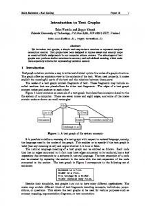
Figure 59. An assembler language program to perform a simple arithmetic calculation in decimal, using the System/360 decimal instruction set
90
The DC instructions for OLDOH, RECPT, and ISSUE and the DS for NEWOH all have operands that start with PL4. The P stands for packed format, and the L4 for a length of 4. (Lengths are always in bytes, never digits.) This is our first contact with a length modifier in a DC instruction. Here, we are specifying that the constants must be four bytes long. If we had omitted the length, the constant generated by the assembler would have been as long as needed to hold the data value we wrote, in this case one byte. (Length modifiers are actually permitted for other types of data, too, although we have had no previous occasion to use them. ) Looking at the assembly listing in Figure 60, we see that the DC entries have resulted in four-byte constants. In each case, with the data shown, there are six zeros, followed by a digit, followed by a hexadecimal F (binary 1111), which is what the assembler used for a plus in this case. Turning back to the instructions of the program, we see that the START, BALR, and USING are standard. The first processing instruction is a new one, Move Characters (MVC). This is an SS fonnat instruction of a slightly different sort: it moves from storage to storage, but there is only one length, because the "sending" and "receiving" fields must be of the same length. That length may be from one to 256 bytes. Looking at the assembled instruction, we see that a length code of 3 has been supplied by the assembler; this is the correct code for a length of four bytes. The length of the operands was implied
000100 000102 000108 00010E 000114 000116 OOOllA OOOllE 000122
05 fO 000102 02 03 F 020 F 014 FA 33 f 020 F 018 FB 33 F 020 F 01C OA 00 0000009F 0000004F 000OOO6F
BEGIN
OlDOH RECPT ISSUE NEWOH
START BAlR USING MVC AP SP SVC
DC DC
DC OS END
256 15,0 -,15 NEWOH.OLOOH NEWOH,RECPT NEWOH,ISSUE 0 Pl4'9' Pl4'4' Pl4'6' Pl4 BEGIN"
Figure 60. Assembly listing of the program of Figure 59
from the data definitions. It is also possible, and frequently necessary, to write explicit lengths to override what the assembler would imply. The generation of an address from the base register contents and the displacement is as before: for instance, for OLDOH the base register contains 102, the displacement is 014; the sum of these is 116, which we see is the address for OLDOH. The purpose of the Move Characters instruction was to get the old on-hand quantity into a location where we can perform arithmetic without disturbing the original quantity. The decimal instructions make no references to the general registers (except, of course, to get the base), so we must provide storage locations for all operations. We do not wish to destroy the old on-hand, so we must arrange f~r the arithmetic results to go somewhere else. In this case, the obvious place is NEWOH, where we want the even-
tual result anyway. In other problems, as we shall see, it is often necessary to provide temporary working storage. The Add Decimal (AP, for Add Packed) instruction adds the quantity received to the old on-hand, which by now is in NEWOH. Note that the result of an arithmetic operation is always stored in the first operand location. The two fields in an Add Decimal instruction need not be the same length, since there are two length codes in the instruction. Here, they are the same, as it happens. The Subtract Decimal (SP) instruction deducts the quantity issued. There is no need for something equivalent to a Store instruction; every instruction already involves two storage addresses, one of which receives the result. The storage dump of Figure 61 shows that the result has been correctly computed.
0000009+ 0000004+ 0000006+ 0000007+
Figure 61. Output of the program of Figures 59 and 60. The four quantities are OLDOH, RECPT, ISSUE, and NEWOH, in that order.
Decimal Operations
91
Decimal Multiplication
For a simple example of decimal multiplication, let us write a program for the computation of a new principal amount. We are given a principal (PRINe), here taken to be four bytes, and an interest factor ( INT) , two bytes; we are to compute the new principal amount after adding in the year's interest. The interest rate of 3% is expressed as the factor 1.03, so that a single multiplication does the whole job. A program is shown in Figure 62. The decimal multiply instruction takes the second operand to be the multiplier; the first operand initially contains the multiplicand, and at the end of .the operation contains the product. However, we cannot begin with a multiply instruction specifying PRINe as the multiplicand, as we might be inclined, because extra space is required. The first operand is required to have at least as many high-order zeros as the size of the multiplier field. We need, therefore, to move the principal to a working storage area having extra positions at the left. These extra positions must be cleared to zero before the multiplication starts. The Zero and Add (ZAP) does just what we need. The effect of the instruction is to clear the first operand (PROD, in this case) to zero, then add the second operand (PRINe) to it. PROD is two bytes longer than PRINe; these extra four digit positions will be cleared to zeros before PRINe is added in. This provides the zeros needed to satisfy the multiplication rule. 000100
05 FO
BEGIN 000102
•• • •
000102 000108 OOOIOE 000114
F8 53 F Fe 51 F FA 51 F 01 00 F
OOOllA 000120 000122 000126 000128 00Ol2E
02 03 F 020 OA 00 00021t89F 103F 050F
026 F 020 026 F 024 026 F 02C 02A F 02B F
021
• • PRINe INT PROD ROUND
Now we multiply. With the sample data shown, the result in PROD will be 00000256367+, as shown in the comments field. We were regarding 2489 as meaning $24.89, and 103 as meaning 1.03, so there are four places to the right of the understood decimal point in the product, which we therefore regard as 0000025.6367+. We would now like to round this off to $25.64. This can be done in a number of ways. Here we simply add a constant (ROUND) properly set up to add a 5 into the second place from the right. The second operand in an Add Decimal instruction is permitted to be shorter than the first (which holds the result). When this is done, any carries that occur are properly propagated. Always bear in mind that the rightmost byte of an operand in decimal arithmetic must have a sign. We might be tempted, for instance, to set up a constant consisting of a 5 without a zero, and add directly into the position where we want to get the rounding. This would be illegal. We are now ready to discard the two digits at the right end of the product. But this is not quite as simple as just not moving them to PRINe, because if we did that, PRINe would not be a legal operand in any subsequent arithmetic operation, since it would not have a sign. Before moving the result back to PRINe, therefore, we must move the sign from where it is, to the byte just to the left. This we can do with a Move Numeric (MVN) instruction, which transmits only the numeric portions of the bytes. The instruction says: Take the numeric portion of the byte at
START 256 BALR 15,0 USING .,IS THE NUMBERS IN THE COMMENTS FIELD ARE THE CJ~TE~TS Of PROD AFTER THE EXECUTION OF EACH I~STRUCTIO~ THE C IS A PLUS SIGN IN THE PACKED FORMAT lAP MP AP MVN THIS IS Mve SVC
DC DC DS DC END
PROD,PRINe PROD,INT PROD,ROUND PROD+ItCI),PROD+5 NOW JHE eONTE~TS OF PRINe,PROD+I 0 PLIt'21t89' Pl2'103' PL6 PLZ'50' 8EGIN
Figure 62. Assembly listing of a program involving a decimal multiplication
92
00 00 00 00
00 00 00 00
00 02 02 02
02 56 56 56
PRI~C
00 02 56 ItC
48 36 41 4:
9C 1C 1C 1C
PROD+5 (which is the rightmost byte of the PROD, and contains the sign) and move it to the byte at PROD+4 (which is the byte to the left and will be the rightmost byte of PRINe after the next instruction); the field to be moved is one byte long. The length for this instruction cannot be left to the assembler; the implied length here would be 6 (the length of PROD), which would destroy the result. The Move Numeric instruction has only one length code, so we need give only one explicit length. Finally, we are ready to move the result to the field where it is required to be at the end of the pro-
gram, PRINe. Remember that PROD is six bytes long. The leftmost byte contains two zeros, we assume: the maximum size of the result is taken to be seven digits. (The validity of such an assumption, as always, is the responsibility of the programmer and systems analyst.) The rightmost byte of PROD contains a digit and sign that we now wish to drop, since they are to the right of the product after rounding. To drop the leftmost byte, we write the address as PROD+l. To drop the rightmost, we need a length of 4, which happens to be the implied length of PRINe, so no explicit length is necessary.
Decimal Operations
93
Decimal Division
Some of the operations in working with the decimal instruction set are different enough from similar operations in other machines that it may be well to pause and consider them in somewhat more detail than we have devoted to other topics. Division is one such operation; the equivalent of shifting, considered later in "Shifting of Decimal Fields", is another. The Divide Decimal (DP) instruction is in the SS format. The first operand is the dividend (the number divided into), the second the divisor (the number divided by). After the operation is completed, the first operand field holds the quotient (at the left) and the remainder (at the right). The remainder is the same length as the divisor. Let us see how this description works out in an example. Suppose we begin with the symbolic locations DIVID and DIVIS as follows: DIVIDbefore DIVIS
000004246+ o3 1 We have indicated DIVID as a "before" value, because after the division the same field will contain both the quotient and the remainder. All operands are in packed format, as with other decimal arithmetic operations. After executing the instruction: DP
+
DIVID,DIVIS
the contents of DIVIS would be unchanged; the contents of DIVID would be: DIVIDafter
00136+030+
This means that 4246 divided by 31 in this way gives a quotient of 136 and a remainder of 30. The divisor was two bytes, so the remainder is two bytes. The quotient takes up the remaining space in the first operand field. The question of the lengths of the various fields can be answered with a useful rule: Number of bytes in dividend = number of number of bytes in quotient bytes in divisor
+
It is perhaps most common to know the number of bytes in the divisor and the number desired in the quotient, the question being how much space to allow in the dividend in order to get the specified size of the quotient. If two of the three lengths are known, the formula can be used to get the length of the third. Note that the formula is stated in terms of the 94
number of bytes, not the number of digits. The reason is that the. first operand field contains only one sign at the beginning, when it is the dividend, but two afterward, when it contains both quotient and remainder. This change would invalidate a rule stated in terms of digits. A very similar rule gives the relationship among decimal points. If we agree that by "decimal places" we mean the number of digits to the right of an assumed decimal point, the rule is: Number of places in dividend = number of places in divisor number of places in quotient In the example given above, we assume that all quantities were integers, that is, have no decimal places. The rule still holds, although in its most elementary form:
+
0=0+0 Let us see what the result would be if we were to arrange the dividend of the example so that it had one decimal place:
+
DIVIDbefore 0 0 0 0 4 2 4 6 0 In other words, we now view the dividend as 4246.0. The result is: DIVIDafter
0 1 3 6 9
+0 2 1 +
The rule says that the quotient should have one decimal place: the dividend had one and the divisor had zero. The quotient must therefore be interpreted as meaning 136.9. (And if anything has to be done with the remainder, it should be taken as meaning 2.1.) Suppose the dividend had been shifted one more place to the left:
+ +
DIVIDbefore 0 0 0 4 2 4 6 0 0 DIVIDafter 1 3 6 9 6 0 2 4 This result should be read as 136.96. What would happen if we tried to set up the dividend with yet one more shift to the left? There is room in the dividend - but there is no more space in the quotient field. This constitutes a divide exception, which occurs whenever the quotient is too large to fit in the field available to it. An interrupt occurs. It is possible to check for the possibility of a divide exception, given sample numbers. To do this, the leftmost digit position of the divisor is aligned with the second digit position from the left of the dividend.
+
When the divisor, so aligned, is less than or equal to the dividend, a divide exception will occur. Take the situation suggested:
DIVIDbefore DIVIS
0 0 4 2 4 6 0 0 0 + 031+
This is the alignment described by the rule. As aligned, the divisor is smaller. We saw before that there would not be enough room for the quotient. This question does depend on the particular numbers involved, of course. Suppose the quantities were aligned the same way but that the dividend were 2246 instead of 4246:
D IVIDbefore DIVIS
002246000+ 031+
This is entirely acceptable. To be completely confident that a divide exception cannot occur, we have to know the maximum possible size of the dividend and the minimum possible size of the divisor, or we must know the maximum size of the quotient. Further examples of decimal division will be given after we have studied shifting, which is often needed to arrange the dividend as desired to give the necessary number of decimal places.
Decimal Operations
95
Shifting of Decimal Fields
Shifting as such is not provided in the System/360 decimal operations. As in other variable-field-length computers with which the reader may be familiar, the equivalent of shifting is performed by appropriate combinations of data movement instructions. The matter is made somewhat more complex by the factor of packed formats, with two digits per byte and with the special status of the sign position. This is simply the price we pay for the increased storage economy of the two-digits-per-byte arrangement. It is also necessary to exercise caution when overlapping fields are to be manipulated in order to be sure that no data is destroyed. This is another occasion where it is absolutely essential to remember that all operands are addressed by the leftmost byte. Let us begin with the simplest type of shift: a decimal right shift of an even number of places. Suppose that we have a five-byte, nine-digit number in SOURCE; we are to move it to a five-byte field named DEST with the last two digits dropped and two zeros at the left. We can do this two ways: with or without disturbing the original contents of SOURCE. Let us do it first without disturbing them. Suppose that the two fields originally contain: SOURCE DEST 12 34 56 78 9S 55 55 55 55 55 The S stands for a plus or minus sign, whichever it might be. The instructions for accomplishing the shift could be as follows, where we have also shown the contents of the two fields after the execution of each instruction: SOURCE
DEST
12 34 56 78 9S
55 12 34 56 78
12 34 56 78 9S
55 12 34 56 7S
12345678 9S
00123456 7S
MVC DEST + 1 ( 4) ,SOURCE MVN DEST +4( 1 ),SOURCE +4
MVC DEST( 1 ),ZERO
In the first Move Characters instruction, an explicit length of 4 is stated; this length applies to both fields. With the first operand address being DEST+l, the four bytes of the destination are the rightmost four. The second operand is given simply as SOURCE, so the four bytes there are the leftmost. The last two digits (one byte) have been dropped. But the sign has been dropped, too, in the process. We accordingly use a Move Numeric instruction to attach it to the shifted number. This must be done 96
with an explicit length of one, to avoid disturbing any of the digits of DEST. Both addresses must be written with the "+4" to pick out the proper one character. Finally, we move one byte of the constant named ZERO (not shown), which contains zeros, to the first byte of DEST. This clears to zero whatever may have been there before. If the contents of SOURCE are no longer needed in their original form, the following sequence is a bit shorter. SOURCE DEST MVN SOURCE+3( 1 ),SOURCE+4 123456 7S 9S 5555555555 ZAP DEST,SOURCE (4) 123456 7S 9S 00 123456 7S
The Move Numeric moves the sign to the byte which will contain the sign in the eventual result. The Zero and Add picks up four bytes of SOURCE and adds them to DEST after clearing DEST to zeros. The Zero and Add has two length codes. For DEST we use the implied length of 5; for SOURCE it is necessary to give an explicit length in order to drop the last two digits. Finally, suppose that for some reason it is necessary to leave the shifted result in SOURCE, without resorting to the expedient of simply moving the sign and appending zeros at the left. MVN ZAP
SOURCE+3( 1 ),SOURCE+4 SOURCE,SOURCE( 4)
SOURCE 12 34 56 7S 9S 00 12 34 56.7S
The sign movement is as before. In the Zero and Add, the second operand is given as SOURCE ( 4), which means a four-byte field the leftmost byte of which has the address SOURCE; this is just 12 34 56 7S. The first operand is simply SOURCE, with its implied length of 5, which means the whole field. It is important to know that this type of overlap is permitted. The relevant statement from the Principles of Operation Manual (A22-6821) is: "The first and second operand fields may overlap when the rightmost byte of the first operand is coincident with or to the right -of the rightmost byte of the second operand." A little study shows that a violation of this rule would result in destroying bytes of the second operand before they have been moved. Let us now turn to a slightly more complex shift, one that involves an odd number of places. This
requires the use of a special instruction designed for the purpose, the Move with Offset. The action of this instruction can be described as follows. The sign of the first operand is not disturbed. The second operand is shifted to the left by four bit positions in moving it to the first operand. Any unused high-order digit positions in the first operand are filled with zeros. Looking at an example, take the fields described in the previous illustration, but suppose that the shift must be three positions instead of two. SOURCE MVO DEST,SOURCE(3) MVN DEST +4( 1 ),SOURCE+4
DEST
12 345678 9S
00 01 234565
12 34 56 78 9S
00 01 23 45 6S
In the Move with Offset, the second operand is given as SOURCE ( 3 ), which picks up a three-byte field starting at the left, namely, the bytes containing 12 34 56. The first operand is DEST, with its implied length of 5. The digits 12 34 56 are moved to DEST with an offset of four bits, or one digit, leaving 00 01 23 45 65 in DEST; the rightmost 5 is the one that was there to begin with. A final Move Numeric attaches the source sign to the destination field. -- If the shift is required to leave the result in SOURCE, only one instruction is needed, since the Move with Offset instruction has no effect on the sign of the first operand, and the left end of the receiving field is filled with zeros. MVO
SOURCE, SOURCE ( 3)
SOURCE 00 01 23 45 6S
The overlapping fields here cause no trouble, since again the movement is to the right of. the original contents. (Actually, overlap of any type is permitted; it is the programmer's responsibility to make sure that the result is meaningful.) A shift to the left presents slightly different problems. Suppose that we have a source field of three bytes this time and a destination of five. Before
SOURCE 12 34 5S
DEST 99 99 99 99 99
Let us take our problem, to move the number at SOURCE to DEST, with four zeros to the right at DEST, and with DEST left ready to do arithmetic. An acceptable sequence of instructions is shown below. MVC DEST (3) ,SOURCE MVC DEST+3(2),ZEROS MVN DEST+4(l),DEST+2 MVN DEST + 2 ( 1) ,ZEROS
SOURCE 12 34 5S 12 34 5S 12 34 5S 12 34 5S
DEST 12 34 12 34 12 34 12 34
5S 5S 5S 50
99 00 00 00
99 00 OS OS
The first Move Characters needs an explicit length on DEST; otherwise, the length would improperly (for us) be implied from DEST as 5. The last two bytes of DEST aTe unaffected by the first Move; a second clears them. A Move Numeric transfers the sign, and a second Move Numeric clears the now extraneous sign that went with the source data on the first Move Characters. Another way to clear the extraneous sign is available, using the And Immediate instruction. cCAnding" two quantities gives a result that has a one bit wherever both operands had r s, and a zero elsewhere. For instance, if we "and" 1100 and 1010, the result is 1000; only in the first bit position did both operands have ones. In the And Immediate instruction (NI), both operands are exactly eight bits long. One of them is given by the byte specified by the address; the other is contained in the instruction itself (which is the reason for the term cCimmediate"). The result replaces the byte specified in storage. In the example at hand, we wish to leave the first four bits of the byte at DEST +2 just as they were; this can be done by placing ones in the corresponding positions in the part of the instruction that will be c'and-ed". (This is usually called the mask.) We wish to make the right four bits of DEST+2 zero, whatever they were before; this can be done by placing zeros in that part of the mask. The mask, in short, should be 11110000, expressed in binary. To write the instruction, we can either convert this to its decimal equivalent 240, or write it in hexadecimal, X'FO'. In other words, we can replace the last instruction with either of the following: NI NI
DEST+2,240 DEST+2,X'FO'
Finally, consider a shift to the left of an odd number of places. For an example, take the data of the preceding illustration, but suppose there are to be three zeros at the right instead of four.
MVC MVC MVN NI MVO
Before DEST ( 3) ,SOURCE DEST+3(2),ZEROS DEST+4( 1),DEST+2 DEST+2,240 DEST( 4),DEST( 3)
SOURCE 12 34 5S 12 34 5S 12 34 5S 12 34 5S 12 34 5S 12 34 5S
DEST 99 99 99 12 34 5S 12 34 5S 12 34 5S 12 34 50 01 23 45
99 99 00 00 00 00
99 99 00 OS OS OS
The first four instructions are just the same as in the previous example, with the And Immediate substituted for the Move Numeric. The final instruction now is a Move with Offset that shifts one digit position to the right.
Decimal Operations
97
Decimal Division with Shifting
We are now prepared to approach a realistic problem in decimal division. Suppose that in a four-byte field named SUM we have the total of the number of hours worked by all the employees in a factory, given to tenths of an hour. In NUMBER we have the number of employees included in the sum; this is a two-byte number. We are to calculate the average workweek, to tenths of an hour, rounded, and place it in a two-byte location named AVERAC. We begin the analysis of the problem knowing that the dividend (SUM) has one decimal place to start, and the divisor (NUMBER) has none. If we set up the division this way, we would get a quotient having one plaee; this would not permit rounding. Evidently we shall have to allow extra places to the right. One more would be sufficient, but this would involve a shift of an odd number of places; it would be simpler for us and faster in the machine to make a shift of two places and simply ignore the extra digit. The dividend therefore should be set up like this: XX XX XX XO 0+ The X's stand for any digits. Now we tum to the rule stating that the number of bytes in the dividend is equal to the number of bytes
000100
OS FO
BEGIN 000102
000102 000108 00010C 000112 000118 OOOllE 000121t 00012b 00012A 000128 000120 00012F 000131
02 91t FD FA 01 02 OA
00 FO 1t1 21 00 01 00
050F OF
F 028 F F 027 F 021t F F 021t F F 025 F F 028 F
02F 029 020 026 OZIt
* * * * *
in the divisor plus the number of bytes in the quotient. We know that we have two bytes in the divisor as it stands. The quotient need be only three: there can be no more than two digits before the decimal point, there will be three after the decimal point, and there will be a sign. (There will be three decimal places in the quotient because there are three in the dividend and none in the divisor.) The dividend evidently should be five bytes. As it happens - which will by no means always be the case - that is just how long it will be as the result of the shifting we decided upon. With this much background, let us now look at the program shown in Figure 63. We assume that it is permissible to destroy the original contents of SUM; if this were not so, it would be a matter of one extra instruction to move the contents of SUM to a working storage location. Notice in the list of constants at the end of the program that a one-byte constant named PAD has been established just after, and therefore to the right of, SUM. Now, instead of actually moving the contents of SUM in order to accomplish a shift, we simply extend the field by one byte. This is the function of the first two instructions. We have assumed, reasonably enough, that the sum is always positive, so
START 256 8ALR 15,0 USING *,15 THE COMMENTS FIELD ON THE FOLLOWING I~STRUCTIONS SHOWS THE CONTENTS OF SUM OR AVERAGE, AFTER THE EXE:UTION OF THE INSTRUCTION
MVC NI DP AP MVN MVC SVC SUM DC PAD OS NUMBER DC AVERAG OS ROUND DC ZERO DC END
SUM+1t l 1) ,ZERO SUM+3,21t0 SUMlS),NUM8ER SUMll),ROUND SUM+1(1),SUM+2 AVERAG,SUM 0 Pllt'019361t8' PLl PL2 '1t87' PlZ PLZ'SO' Pll' 0' BEGIN
01 01 39 39 39 39
93 93 76 81 8+ 8+
61t 61t 3+ 3+ 3+
8+ 0+
80 21 21 21
0+ 9+ 9+ 9+
Figure 63. Assembly listing of a program involving decimal division and the equivalent of decimal shifting
98
a plus sign is moved with the first Move Characters, and the original sign is simply erased with the And Immediate. The Divide Decimal might seem to carry the possibility of a divide exception. We must fall back on a knowledge of the data, which is the eventual foundation of any intelligent programming. We simply
observe that the average hours worked would not be as great as 100 hours - and anything less can be contained in the space provided. Rounding is accomplished by adding 5 in the proper position. We move the sign to where it is needed, and finally transfer the result to the specified location in storage.
Decimal Operations
99
Format and Base Conversions
It is often necessary to convert from zoned to packed format and vice versa, and to convert between binary and decimal form. In this sectiQn we shall examine an illustrative problem that involves both types of conversion, and the special instructions available to make them relatively simple. We are given a fullword named REG, in binary format. The three-byte field named PREM was read directly from a card on which the sign was in the high-order position, instead of the low-order. That is, a positive number was punched with a 12 zone over the leftmost digit, and a minus number was punched with an 11 zone over the leftmost digit. We are required to place the sum of REG and PREM in ANS, as a decimal number in the normal zoned format, that is, with the sign in the zone of the low-order byte. The zone bits that result in a byte in storage from a 12 zone on the card, are the zone bits required for a plus sign in the EBCDIC zoned format in storage. An 11 zone likewise is translated into the correct zone bits for a minus sign. Our problem, then, is simply
000100
05 Fa
• •
• •
000102 000106 00010A 00010E 000112 000114 000118 00011E 000122 000126 00012C 000132 000134 000134 000138 00013C 00013F 000144 000148 000150
43 54 43 54 16 42 F2 58 4E FA F3 OA
50 50 60 60 56 50 12 60 60
F F F F
F F F F 71 F 57 F 00
OOOOOOFO OOOOOOOF
03A 032 03C 036
•
1101 0011
1111 0111
1111 1001
With the card column assignments we have described, this is the EBCDIC representation of -379. The program begins with a new instruction: Insert Character (IC). This is an RX format instruction that gets one character (byte) from the specified storage location and places it in the rightmost byte position of the register named. The other bit positions of the register are not disturbed. We do not know what might be in them, but it will not matter, as it happens, since the following instruction clears them. This is an And to erase the numeric bits of the bighorder character.
START 256 BALR 15,0 USING -,15
BEGIN 000102
to move the zone bits of the high-order byte to the zone bits of the low-order byte. In the program of Figure 64 we have shown at the right of the first half-dozen instructions the contents of the last eight bit positions of registers 5 and 6, to aid in understanding how the instructions operate on sample data consisting of the three bytes:
THE COMMENTS FIELD ON THE FOLLOWING INSTRUCTIJ~S SHOWS THE LAST BYTE (. 8 BITS) Uf RE~ISTERS 5 A'40 6 AFTER THE EXECUTION OF EACH INSTRUCTIJ~
03C 030 F 03A 042 046 046 F 030 04E F 046 MASKI MASK2 PREM WORK REG DOUBLE ANS
IC N IC N OR STC PACK L CVO AP UNPK SVC OS DC DC DS DS
os os os
END
5,PREM 5,MASKl 6,PREM+2 6,MASK2 5,6 5,PREM+2 WORK,PREM 6,REG 6,DOUBLE OOUBlE,WORK ANS,OOUBlE 0 OF X'OOOOOOFO' X'OOOOOOOF' Zl3 Pl2
1101 1101 1101 1101 1101 1101
0011 0000 0000 0000 1001 1001
1111 0000 0000 0000
F
0
Zl6 BEGIN
Figure 64. Assembly listing of a program that moves zone bits from one byte to another, converts a number to packed format, converts another number from binary to decimal, and does arithmetic in decimal
100
1001 1001 1001 10(il
Next we perform the similar operations on the loworder byte, using register 6, except that this. time we erase the zone bits. Now we have in register 6 the numeric bits of the low-order byte, and in register 5 the zone bits that are to be attached to that byte. They can be combined with an Or Register (OR) instruction. "Or-ing" two operands is a bit-by-bit operation that results in a 1 wherever either operand had a 1, and zero where both had zero. The result of this instruction is to combine the two groups of bits, leaving the result in register 5. This now is the byte that we want in the low-order position, so we use a Store Character instruction (STC) to place it there. Insert Character and Store Character do not require the character to be on any sort of integral boundary. They are the only index able instructions for which this is true. The various decimal instructions do not require boundary alignment either, of course, but they are not indexable. The two And ( N ) instructions, however, do require their operands to be on fuIIword boundaries. This is the purpose of the DS OF before the DC's for the masks. At this point we have merely got the sign where it is expected to be in the zoned format of a decimal number. Now we must convert from zoned to packed format, which is the function of the PACK instruc-
tion. The secoild operand names a field in zoned format; the first names the field where the packed format should be stored. Both fields carry length codes. Here, we are able to leave the lengths implied: three bytes for PREM and two for WORK (two bytes allow space enough for three digits and sign in packed format). The PACK instruction ignores all zones except the rightmost, which is taken to carry the sign. Therefore we can leave the zone of the high-order byte as it was without disturbing the operation. With the PREM amount finally in packed format, we are almost ready to do the addition - but not quite, because the REG amount is still in binary. The next instruction, accordingly, is a Load followed by a Convert to Decimal (CVD). Convert to Decimal takes the binary number in the specified register and converts it to packed format decimal in the location given, which must be an aligned on a doubleword. At last it is possible to do the addition, which is done in decimal. A final instruction, Unpack (UNPK), converts back from packed to zoned, as required in the problem statement. This will leave the final answer with the sign in the zone bits of the low-order byte, which was stated to be the desired position for whatever processing might follow. H it were necessary to get the result into the same format as PREM originally was, we could of course do so.
Decimal Operations
101
Decimal Comparison: Overtime Pay
Logical tests and decisions are as necessary in decimal operations as elsewhere. The System/360 provides a Compare Decimal instruction, and the condition code is set as a result of this and three arithmetic instructions. In this section we shall explore an example that uses the Compare Decimal instruction. For an example we take the familiar calculation of gross pay, with time-and-a-half for hours over 40. We have a RATE, given in dollars and cents, and an HOURS, to tenths of an hour. We are to place in GROSS the total wages earned. There are several ways to approach the overtime computation. We choose here to begin by figuring the pay at the straight-time rate, on the full amount in HOURS. We then inspect the hours worked, and if it was not over 40 the job is finished. If there was overtime, we multiply the hours over 40 by the pay rate, and multiply this product by one-half to get the premium, which is then added to the previous figure. Several other ways to arrange the sequence of deci-
000100
05 FO
BEGIN 000102
000102 000108 00010E 000114 00011A 000120 000124 00012A 000130 000136
ooonc
000142 000148 00014E 000150 000152 000154 000158 00015C 000150 00015F
F8 31 F 056 Fe 31 F 056 FA 30 F 056 F1 32 F 052 F9 11 F 050 47 CO F 04C F8 31 F 056 F8 31 F 056 Fe 31 F 056 FC 30 F 056 FA 31 F 056 01 00 F 058 FA 32 F 052 OA 00 175F 446F OOOOOOOF SF 050F 400F
F F F F F
050 04E 05A 056 050
F F F F F F F
050 050 04E 05A 058 059 056
• • • • •
OUT RATE HOURS GROSS WORK FIVE FIFTY FORTY
sions and multiplications are obviously possible. This one probably minimizes the computation time if most employees do not work overtime; if most did work overtime, a diHerent sequence might be a little better. The program in Figure 65 begins with a three-instruction sequence to set up the multiplicand in a work area, multiply, and round. The Move with Offset instruction drops one digit in the move; this is the extra digit that was rounded off. The Move with Offset instruction does not transmit the sign; we have shown GROSS as a DC to get a plus sign there from the outset. Since the pay can never properly be negative, the plus sign will simply remain there throughout the operation of the program. The Compare Decimal ( CP ) instruction is not greatly different in concept from Compare instructions we have seen previously. The two operands are compared, algebraically; the condition code is set depending on the relative sizes of the two; neither operand is changed. The mask of 12 on the Branch on Con-
START 256 8ALR 15,0 USING -,15 THE COMMENTS FIELD SHOWS TH~ CONTENTS OF MO~( O~ bRJSS, WHICHEVER IS OPERAND 1 ON A PARTICULAR I~ST~UCTIJ~, AFTER THE EXECUTION OF THE INSTRUCTION lAP MP AP HVO CP BC ZAP SP MP MP AP MVN AP SVC DC DC DC OS DC DC DC END
WORK,HOURS WORK,RATE WORK,FIVE GROSS,WORK(]) HOURS,FORTY 12,OUT WORK,HDURS WORK,FORTY WORK,RATE WORK,FIVE WORK, F IffY WORK+2(1),WORK+3 GROSS, WORK (3) 0 PL2'1.75' PL2'44.6' PL4'O' Pl4 PL1'S' PL2'50' PL2'40.0' BEGIN
00 00 00 00
00 18 18 01
44 bC 05 OC 05 5C 80 ~c
00 00 00 00 00 00 00
00 00 08 40 40 40 08
44 6e 04 be O~
Figure 65. Assembly listing of a program that computes a man's gross pay, including any overtime pay
102
De
25 OC 30 DC 3COC 20 8C
dition will cause a branch if the contents of HOURS are less than or equal to FORTY, in which case there is no overtime to compute, and we simply branch out to whatever follows. (In this example we do not show the continuation of the computation.) If the man did work more than 40 hours, we compute his pay on the amount over 40, then multiply by 5, which we view as having a decimal point, that is, as being one-half. This is done because we have already computed the straight-time pay on the amount over 40; now we need only to compute the extra premium. After the multiplication by 5 we round off, using a different rounding constant this time because the multiplication by 0.5 has added another decimal
place. (It is necessary to check that there is sufficient space in WORK to satisfy the rule about at least as many zeros as the size of the multiplier. Assuming that no employee could make $1000 in one week, the rule is satisfied.) After a Move Numerical to move the sign, we can add the rounded amount to GROSS to get the total pay. In the Add Decimal, note the length of 3 to drop the last byte, which after rounding is extraneous. We now reach the termination of the program, the same point to which we transferred if there was no overtime. In other words, both paths would lead, in a real program, to the same continuation point.
DecimaI Operations
103
The Social Security Problem in Decimal
For a little further practice in applying decimal operations, we may rewrite the Social Security calculation of Figure 51 in the chapter on «Fixed-Point Operations". The logic of the decimal program shown in Figure 66 is the same as that of the earlier one. No new instructions are introduced, so a few notes should be all that is required to explain the program. We begin by moving the old year-to-date to the new year-to-date location. The purpose is simply to get one of the two operands in the following addition where we want the result to be. Following is a Zero and Add to get the new year-to-date into working location where we can continue the processing without disturbing the NEWYTD location. From here on, the right side of Figure 66 shows the contents of the
Q00100 000102 000108
00010E 000114 00011A 000120 000126 00012C 000130 000136 00013C 000142 000148 00014A 000140 000151 000155 000158 00015.8 00015E 000161 000164 000168
BEGIN
05 FO
000102 02 03 F 04F F 048 FA 32 F 04F F 0~8
F8 63 F 066 FC 62 F 066 FA 63 F 066 01 00 F 069 F9 32 F 066 47 40 F 034 02 02 F 067 02 02 F 056 FB 22 F 067 02 02 F 059 OA 00 10607F 0475091F 17219F 17400F 36250F 0500000F
F 04F F 05F F 062
F 06C F 05C F F F F
05C 067 053 067
* * * * *
START BALR USING MVC AP
WORK field for sample data as shown in the DC instructions. In the Multiply Decimal instruction that computes the Social Security tax on the new year-to-date figure, we use a constant for the 3%% that has been set up with an extra zero at the right. This was done to put the product in a position where a Move with Offset would not be necessary. As it has been done, after rounding and moving the sign, we can carry out all following operations on the Social Security amount on the second, third and fourth bytes of WORK. Since the implied length from the DC is 7, an explicit length must be given. The remaining operations closely parallel the ones in the earlier version.
256 15,0 *,15 NEWYTD,OLDYTD NEWYTD,EARN
THE COMMENTS FIELD ON THE FOLLOWING INSTRUCTION SHOWS THE CONTENTS OF WORK, IN EVERY CASE, AFTER THE EXECUTION OF THE INSTRUCTION
ZAP MP AP MVN CP BC MVC UNDER MVC SP MVC SVC EARN DC OLOYTO DC NEWYTD OS OLOSS DC NEWSS OS TAX OS C174 DC C358 DC HALF DC WORK OS END
WORK,NEWYTO WORK,C358 WORK,HALF WORK+3(1),WORK+6 WORK(4),C174 4,UNOER WORK +1 ( 3) , C174 NEWSS(3),WORK+1 WORK+1 (3) ,OLOSS TAX(3),WORK+l 0 PL3'106.07' PL4'4750.91' PL4 PL3'172.19' PL3 PL3 PL3' 174.00' PL3'36250' PL4'500000' PL7 BEGIN
Figure 66. Assembly listing of a program to compute Social Security tax in decimal
104
00 00 00 00 00 00 00 00 00 00
00 17 17 17 17 17 17 17 00 00
00 60 60 60 60 60 40 40 18 18
04 65 70 7+ 7+ 7+ 0+ 0+ 1+ 1+
85 52 52 52 52 52 52 52 52 52
69 50 50 50 50 50 50 50 50 50
8+ 0+ 0+ 0+ 0+ 0+ 0+ 0+ 0+ 0+
The "Indian" Problem
A certain programming exercise has been done by so many generations of IBM students that it is a classic. We present it here, worked out with the calculation in decimal and the counting in binary. The Indians sold Manhattan Island in 1627 for $24. If the Indians had banked their $24 in 1627, what would their bank balance be in 1965 at a 3% interest rate compounded annually? To make the problem a little more interesting, let us assume that the principal, $24, the interest rate
000100
05 FO
000102 000106 00010A 000110 000116 00011C 000120 000126 00012e 000132 000138 00013E 000142 000148 00014A 000140 0001S0 000154 000158 000159 OOOlSC 000150 000160 000164 000167 00016A 000171 000178 000180 000182 000188
58 EO F 052 SO EO 0 06C F2 63 F 068 F2 12 F 06F F2 72 F 076 4F 40 F 076 FC 61 F 068 FA 61 F 068 01 00 F 060 02 05 F 080 F8 65 f 068 46 40 F OlE F3 86 F 086 OA 01 C01001 000158 OA 00 00000148 03 000188 09 000001 f2f4FOCO F1FOC3 f3F3C8
BEGIN 000102
050F
F OSE F 062 F 065 F F F F f
06F 07E 06E 06B 080
lOOP
f 068 ERROR
AOCON Cll
factor, 1.03, and the number of years, 338, are all initially in zoned format. The program of Figure 67 accordingly begins with three PACK instructions to get from zoned to packed format. The general scheme of the program will be to multiply the principal by 1.03 as many times as there are years. In other words, we shall go around a loop repeatedly, each time performing a multiplication and subtracting 1 from a count. When the count has been reduced to zero, the computation of the balance is completed. This counting down from 338 to zero could, of course, be done in decimal, and using
START 8AlR USING l ST PACK PACK PACK CV8 MP AP MVN MVC ZAP BCT UNPK SVC DC DC SVC DC DC OC DC DC DC DC OC OS OS OS DC
PRINtl INTI YEARSI PRINCP INTP YEARSP ROUND OS TEMP BALNCE OS END
256 15,0 *,15 14,AOCON 14,108 PRINCP,PRINCl IN,r~INTI
YEARSP,YEARSl 4,YEARSP PRINCP,INTP PRINCP,ROUND PRINCP+S(1),PRINCP+6 TEMP,PRINCP PRINCP,fEMP 4,lOOP BAlNCE,PRINCP 1 X'COI001' Al3(Cl1) 0 AIERROR) X'03' Al3(BAlNCE) Al1(9) Al3(1) Il4'24.00' Ill'I.03' Il3'338' PLl Pl2 0 PlZ'50' PL6 Pl9 BEGIN
Figure 67. Assembly listing of a program to compute compound interest (the "Indian" problem)
Decimal Operations
lOS
a Compare Decimal instruction. It is better programming practice, however, to remove time-consuming operations from the repeated part of the loop wherever possible. Doing the combination of an Add Decimal, a Compare Decimal, and a Branch on Condition is much more time-consuming than another approach that is available to us. This other way is to convert the years to binary, once, before entering the loop, then use a Branch on Count (BCT) to subtract 1, test, and conditionally branch. The fourth instruction of the program is therefore a Convert to Binary (CVB) instruction, which in our program takes the doubleword at YEARSP and converts to a binary number in register 4. The Convert to- Binary instruction requires an aligned doubleword operand, which is why the DS for YEARSP was set up as it was instead of with a CLB. The repeated part of the loop starts with a Multiply Decimal that should by now be moderately familiar. PRINCP was set up to be long enough to hold the size of number that previous runnings of the program have shown will be necessary. The programmer facing this problem completely fresh would have to
106
make either some preliminary calculations as to the possible size, or a guess. N ow comes a familiar sequence of decimal instructions to round, move the sign, and shift right two digits (one byte). One might be tempted to replace the Move Characters and Zero and Add instructions with a single one of the sort: MVC
PRINCP+1(6),PRINCP
thinking that a right-to-Ieft operation would permit this sort of overlap. A check of the Principles of Operation Manual (A22-6821), however, discloses that Move Characters works from left to right I The instruction suggested would therefore propagate the leftmost character through the entire field I This can be quite useful on occasion, and is permitted, but it is hardly what we want here. Overlapping fields must be treated with caution. The Branch on Count subtracts 1 from register 4; if the result is not zero, a branch occurs. If the result is zero, the next instruction in sequence is taken. The loop will be carried out 338 times, as required. A final Unpack instruction puts the result into a location named BALANCE in zoned format. The answer is $523,998.22.
Questions and Exercises
la. Write the assembler instruction to define a packed decimal constant of 3 to be named CON3 and to occupy 5 bytes of storage. b. Show how this constant appears on the assembly listing. 2. A length code in an instruction is called implied if it is supplied by the on the basis of------An explicit length code is supplied by the 3. An explicit length code is (equal to, one more than, one less than) the actual number of bytes to be dealt with. 4. The length code in the object instruction is (equal to, one more than, one less than) the actual number of bytes to be dealt with. 5a. The MP instruction specifies the location of - - - - - - - - - - - - - - in the first operand, and the location of the - - - - - - - in the second operand. b. Where is the product at the end of the multiplication? 6. If there were two successive DC statements of: PRINC DC PL4'2489' INT DC PL2'103' and PRINC were assigned a location of 158: a. What would be in the storage locations assigned to these constants? b. To what storage location would the operand INT -2 refer? 7. A DP instruction specifies in its first operand the location of the , and in its second operand the location of the . Where will the quotient and remainder be after the completion of a DP instruction? 8. Assume three factors: QUAN - 4 whole numbers TCOST - 6 whole numbers and 2 decimal places AVCOST - 6 whole numbers and 2 decimal places The problem is to divide QUAN into TCOST to develop a quotient AVCOST, which is not to be rounded. a. How many decimal places must the dividend contain to develop a proper quotient?
b. What must be the minimum size (in bytes) of the area in which the dividend is located at the time the DP instruction is executed?
9. Assume two fields: SOURCE containing 66 55 44 33 22 11 DEST containing 1122 33 44 55 6S (S = sign) Show the contents of SOURCE and DEST after the execution of the instructions below. In each case, assume that before execution the contents of SOURCE and DEST ar€ as shown above. a. MVC DEST+2(3),SOURCE 'b. MVN DEST+3(1),DEST+5 c. MVO DEST,SOURCE+2(2) 10. Assume the same fields (SOURCE and DEST) as given in question 9. Would the instruction ZAP DEST,SOURCE be a legitimate one? It not, why not? 11. Assume a 5-byte field called FACTOR, which contains 12 34 56 78 9S (S = sign). a. Write the instruction or instructions to store the leftmost 8 digits (12345678) and the sign in a 6byte field called RESULT. b. Write the instruction or instructions to store the leftmost 7 digits and the sign in RESULT. 12a. The NI ( And Immediate) instruction is a - - - - - - - format instruction. b. Write the NI instru"Ction( s) that will change the contents of a field named HOLD from 11 22 33 44 6S to 00 22 33 44 6S. c. 11 22 33 44 6S to 11 22 33 04 6S. 13. What is the difference between the And Immediate and Or Immediate instructions? 14. Decimal arithmetic can be performed only on (zoned decimal, packed decimal) fields. 15. What instruction converts information from zoned decimal to packed decimal form? 16. What instruction converts information from packed decimal to zoned qecimal form? 17. Write DC's to store the number 578 as: a. A fixed-point number. b. A 3·byte zoned decimal number. c. A 2-byte packed decimal number. 18. Write a DC to store the hexadecimal equivalent of 75 10 . Decimal Operations
107
19. Write an instruction that will place a byte named OLD in the rightmost byte position of register 6 without disturbing the remaining positions of register 6. 20. Write an instruction that will store the contents of the rightmost byte position of register 6 in a storage byte named OLD. 21. Consider the following excerpts from an assembly listing. MASK is located at 136
108
N
6,~ASK
MASK DC X'()()OOOOOF' a. Will the N 6,MASK instruction be successfully executed? If not, why not? b. If not, what statement or statements could be inserted to correct the condition? c. How could the DC itself be rewritten to correct the situation?
Chapter 7: Logical Operations on Characters and Bits
This chapter discusses the subject of logical operations through the medium of several illustrative programs. These illustrative programs were designed to bring out various aspects of the use of logical operations, with the logic being the primary focus of the example. The reader will realize, of course, that, in practical applications, logic is one of many tools and techniques used in a complete program. The first example demo~strates the logic involved in sorting three items into ascending sequence. Two sections show numerous examples of tests on com-
binations of bits in a byte and the setting of bit combinations. Another major example uses the computation of a check digit in a self-checking number to illustrate logical operations on a sequence of characters. A final example involves a series of bit and byte operations on input data fields. Instructions emphasized in this chapter include the various types of comparisons, Insert Character, Store Character, Test Under Mask, the various forms of And and Or, and Branch on Condition.
Alphameric Comparison: An Address Sort
A frequent requirement in commercial data processing is the comparison of two alphameric quantities, such as names or account numbers, for relative magnitude. Sometimes this is done to establish correspondence between records in two files, both of which are in ascending sequence on the name or account number, which is called the key. Another common application is in arranging a group of records into ascending or descending sequence on keys contained in the records. Let us consider this problem, which is usually called sorting, although sequencing might in some ways be a preferable term. The problem will be to arrange three "records" of 13 characters each into ascending sequence on a five-character key contained in the middle five positions of the record. The rearranged records are to be moved to three new record areas named SMALL, MEDIUM, and LARGE. The basic operation in the program will be an alphameric comparison of two five-character keys to determine relative magnitude. This will be done with a Compare Logical Character instruction (CLC). The word "logical" in the name means that in comparing two characters, all possible bit combinations are
valid, and the comparison is made on a binary basis. In a table of EBCDIC character codes, we can see that, according to such a scheme, all letters will be "smaller" than all digits; if punctuation characters occur, they rank smaller than either letters or digits. (In ASCII coding, the positions of letters and digits are just the opposite.) For our purposes here, we are not too concerned about the intricacies of where the various characters are ranked by the the comparison instruction 0 ; all we really need to know is that names will be correctly alphabetized and that digits are consistently ranked somewhere. The word "character" in Compare Logical Character is meant to imply that the instruction is in the SS format and operates on variable-length fields. There is one length code, which applies to both operands. The comparison is from left to right, and continues either until two characters are found that are not the same, or until the end of the fields is reached. (As soon as two characters are found to be different, there is no need to continue the comparison. If we °Called the machine's collating sequence Logical Operations on Characters and Bits
109
are comparing SMITH and SMYTH, we know that SMITH is "smaller" as soon as the I and Yare compared, regardless of what characters follow.) With this much preliminary, let us consider the program in Figure 68. Perhaps we should begin by looking at the storage allocation. We see DS entries for A, B, and C, the three original records; these are 13 characters each. Next come three entries that define the addresses of A, B, and C, as ADDRA, ADDRB, and ADDRC, respectively. When we write ADDRA as the operand in a Load, what we get in the register is not A, but its address. Finally there are DS's for SMALL, MEDIUM, and LARGE, where the results go. The processing begins by loading the addresses of A, B, and C into registers 2, 3, and 4, respectively, with a Load Multiple. Now we begin a sequence of comparisons and (if necessary) interchanges that will put the three quantities into ascending sequence. We first compare A and B. If A is already equal to or smaller than B, we do nothing; but, if A is larger, we interchange the addresses of A and B. Let us see how this works. The Compare Logical Character (CLC) instruction following the Load ~1ultiple is written with explicit base registers and explicit lengths. The general format of the instruction is CLC D1(L1,B1),D2(B2)
05 FO
000102 000106 00010C 00011C 000112 000114 000116 00011C 00012J 000122 000124 000126 OOO12C 00013C 000132 000134 0OO13{; OOO13C 00,)142 000148 00014A 000157 000164 000174 000178 0OO17C 000180 00018C
98 24 F 012
oca 102
0OO19~
D5 47 113 18 18 D5 47 18 III
18 D5 47 If!
18 18
04 CO 62 23 36 04 CO 62 24 46 04 CO 63 34 46
START BALR USING LM CLC BC LR LR LR X CLC BC LR LR LR Y CLC BC LR LR LR MOVE MVC MVC II-VC SVC A DS B OS C DS ADORA DC ADURB DC A.DORC DC SMALL OS MEDI UM OS LAR.GE OS END BEGIN
OOOloe
2 004 3 004 F 014
2 004 4 004 F 024
CC4 4 004 F 034 3
ac F 07E 2 oeo D2 OC F OAB 3 000 D2 OC F 098 4 oeo OA 00
02
('IOOOO14A '](000151 00000164
As we have written the instruction here, the displacement for operand 1 is 4, the length of both operands is 5, the base register for the first operand is 2, the displacement for the second operand is 4, and the base register for the second operand is 3. Exactly what character positions do these addresses refer to? Remember that base register 2 contains the address of A. This base, plus a displacement of 4, gives the address of the fourth character from the leftmost character of the c'record". Since we said that the key was to be the middle five characters of each record, what we have here is the address of the leftmost character of the key of record A. The length of the key is given explicitly as 5. Operand 2, likewise, gives the address of the key of record B. The Branch on Condition asks whether the first operand (the key of A) was less than or equal to the second operand (the key of B). If so, there is a branch down to the next comparison, at X, since A and B are already in correct sequence. If the Branch is not taken, we reach the "interchange" of A and B. Now, an actual interchange of two 13-character records is a somewhat time-consuming operation; and, of course, this example is only symbolic of real applications, where the records to be sorted might be hundreds of characters long. It is much faster to interchange the addresses of A and B than to interchange the records themselves; the
256 15,0 ·,15 2,4,ADDRA 4(5,2),4(31 12,.X 6,2 2,3 3,6 4(5,2),414), 12,Y 6,2 2,4 4,6 415,3),414) 12,MOVE 6,3 3,4 4,6 SMALL,C(21 MEOIUM,0(3) LAR~[,OI4)
C
LOAD REGISTERS WITH ADDRESSES COMPARE A AND B BRANCH IF A ALREADY LESS OR EQUAL INTERCHANGE ADDRESSES OF A AND B X X
COMPARE A AND C BRANCH IF A ALREADY LESS OR EQUAL INTERCHANGE ADDRESSES OF A AND C X X
COMPARE BAND C BRA~C~ IF B ALREADY LESS OR EUUAL INTEPCHANGE ADDRESSES OF BAND C X X
ADDRESS OF SMALLEST nf THREE IS NO .. IN 2 LI KEwI SE fOR MEDIUM, IN REGISTER 3 LIKE~ISE FOR LARGEST, II'. REGISTER 4 PROGRAM TERMINATIO~
CLl3 CLl3 CLl3 A(A) A( B) A(C) CLl3 CLl3 CLl3 BEGIN
Figure 68. A program to sort three 13-character items into ascending sequence on keys in the middle five characters of each item. The three items are in A, B, and C; the sorted items are placed in SMALL, MEDIUM, and LARGE.
110
addresses are only four characters instead of 13, and, as written here, they are in registers rather than in storage. Three Load Register instructions, which are executed very rapidly, carry out the interchange. Now, when we continue to the comparison at X, what is the address situatiQn?We know that we want to compare whichever of A and B was the smaller with C. Accordingly, we write addresses using base registers 2 and 4. We cannot say whether 2 contains the address of A or B; but, whichever it is, it is the address of the smaller of the two. That is all we need to know. After this comparison and (possible) interchange, we are guaranteed that base register 2 contains the address of the smallest of the three numbers. A final comparison using whatever addresses are by now in registers 3 and 4 gives us the address of the "middle" number in 3 and the address of the largest of the three in 4. Now, at MOVE, we are able to write three instructions that perform the rearrangement. In the first Move Characters, we pick up the smallest, using whatever is in base register 2. The displacement this time is zero; we want the entire 13 characters. The length can be left implicit this time; it will be implied from SMALL, which is 13 characters long. Figure 69 shows the contents of registers 2, 3, and 4 at four points in the program: at the beginning, at X, at Y, and at MOVE. The three original data items, in order, were 1111CCCCC1111, 2222BBBBB2222,
and 3333AAAAA3333. In other words, the items were in reverse order according to their keys.
Register 2
Register 3
Register 4
Before
00OOO14A
00000157
00000164
x
00000157
oooo014A
00000164
y
00000164
oooo014A
00000157
MOVE
00000164
00000157
0OOOOl4A
Figure 69. The contents of registers 2, 3, and 4 at four points during the execution of the program of Figure 68. The original items were in reverse order according to their keys.
In practical applications there are usually far too many records to be sorted internally for the keys of all of them to be held in base registers. On the other hand, the records are ordinarily so long that it is a saving in time to work with addresses held in storage rather than with the records themselves. The basic concept suggested here can readily be generalized.
Logical Operations on Characters and Bits
111
Logical Tests: The Wallpaper Problem
Problems sometimes arise in which it is necessary to work with combinations of logical tests, where each test is of the yes-or-no variety. Such situations are often most conveniently attacked as logical operations on sets of binary variables. If the data can be suitably arranged, the tests can sometimes be made very simply with the Test Under Mask (TM) instruction. Consider the following problem, which is intended to be illustrative only. Suppose that a wallpaper manufacturer classifies his products according to the colors each style contains. There are only four colors: red, blue, green, and orange. For each style there is a group of four bits at the right-hand side of a character named P ATTRN. These bits represent, from left to right, the four colors, in the order named. For each bit position, a 1 means that the style contains the color, and a zero means that it does not. For instance, 0001 would mean a style with orange only; 1010 would describe a pattern with red and green, but no blue or orange. We wish to see how to set up instructions to answer questions of the following sort: Does this pattern have either red or green, or both? Does this pattern have red, or green, or orange, or any two of these, but not all three? Does this pattern have both red and orange, whether or not it has blue and/or green? Does this pattern have neither green nor orange? Does this pattern have red but not orange? Let us consider these questions in order. Red, or green, or both. Looking at the four colorbits, we are interested in the first and third. If we let X stand for a bit that we want to be a 1, and D for a bit about which we don't care, the required pattern is XDXD. The Test Under Mask instruction can handle this situation with just two instructions: TM PATTRN,10 BC 5,YES In the Test Under Mask instruction, the 10 is the mask, written here in decimal. Writing it out as a binary number, we have 00001010. The two 1's here pick out the two bits in the character at P ATTRN that are to be tested. The resulting condition codes have meanings as follows: a code of zero means that all the selected bits were zero; a code of 1 means that the selected bits were mixed zeros and 1's; a condition code of 3 means that the selected bits were all 1's. (A condition code of 2 is not possible with 112
this instruction.) The question to be answered was: Does this pattern contain either red, or green, or both? We have selected the two bits that describe the presence or absence of red and green. If the two bits selected were a mixture of zeros and 1's, we have just one of the two colors in the pattern. If the two bits selected were both 1's, the pattern contains both colors. Either situation answers the question affirmatively. We accordingly write a Branch on Condition instruction that tests for the presence of condition codes 1 or 3. (Remember that 8, 4, 2, and 1 in the Rl field of a BC correspond to condition codes of 0, 1, 2, and 3, respectively. Branch on Condition with an R1 field of 5, therefore, tests for a condition code of either 1 or 3.) At YES, we assume, there would be instructions to do whatever action depended on an affirmative answer to the question. Red, green, or orange, but not all three. Here we need a mask that tests bits according to this scheme: XDXX. The necessary mask is 00001011, which is 11 in decimal. The condition code that describes the wallpaper design specified is 1: mixed zeros and 1's. We want at least one 1, and two would do, but we must have at least one zero among the bits tested because the pattern must not have all three colors. The required instructions are: TM BC
PATTRN,l1 4,YES
Both red and orange. This one is fairly simple. We pick out bits according to XDDX, and then ask whether they are all (both) l's. The instructions are: TM BC
PATTRN,9 I,YES
Neither green nor orange. This is not very difficult, either. The bits are shown by DDXX, and we want to know whether they are all (both) zero. The instructions are: TM PATTRN,3 BC 8,YES Red but not orange. This is a different problem that cannot be done with a single Test Under Mask. We turn to the logical instructions And, and Exclusive Or. The bits in question are shown as X's in XDDX. We want the leftmost X to be a 1, and the rightmost to be a zero. We begin by moving PATTRN to WORK, where we may destroy its original value. An And Immediate instruction with an immediate portion of 9 (in binary:
00001001) erases all bits except the ones we want. In the two positions of interest, if there was a 1 before, there still is, and if there was a zero, there still is. All other bit positions are guaranteed to be zero. If the pattern is to pass the test, there must now be exactly one 1 in WORK, and it must be in this position: ooooxooo. Whether this is so could be determined with a comparison or two Test Under Mask instructions. But let us continue with the logical operations. Exclusive Or is a logical operation; like And and Or, it is a bit-by-bit operation. In each bit position, the result is 1 if the two operands had exactly one 1 in that position; the result bit is zero if both operand bits were zero or if both were 1. Suppose we write an Exclusive Or Immediate in which the immediate portion is 00001000; the 1 here is in the position for red. The result after the Exclusive Or Immediate will be zero in this position if there had been a 1, and vice versa. In other words, if the result really was 00001000 after the And Immediate, there will be all zeros after the Exclusive Or Immediate. If, on the other hand, there was a zero in the position for red, there will now be a 1. And if there was a 1 in the position for orange, there will still be a 1 there. In short, a zero result corresponds to an answer of «yes, there is red but no orange". As it happens, the various logical operations all set the condition code; and, in the case of the Exclusive Or, a condition code of zero means that the result was zero. The program can thus be: MVC WORK,PATTRN NI WORK,9 XI WORK,8 Be 8,YES
Test Under Mask is a most useful instruction where it applies, and its usefulness is by no means limited to color-blind wallpaper manufacturers. It is useful partly because it is selective, testing only the bits specified by the mask, and partly because it gives a three-way description of the selected bits: all zero, mixed, or all 1's. It does have the drawback, however, that only one character can be tested at a time. If it were necessary to extend the application to cover, say, 20 different yes-no descriptions instead of the four we had in the wallpaper situation, the Test Under Mask instruction could not be used, except in combinations that would get rather involved. In such a situation, we would turn instead to the RX forms of the logical instructions. After moving the pattern to a register, which can hold a 32-bit pattern, we would use an And to "select" the bits of interest. The operand of the And instruction would be a fullword in stQrage that has 1's where there are bits of interest in the pattern. What we do next depends on our answers to certain questions. Question: Were any of the selected bits 1's? Action: We need only test the condition code, which tells whether the result was all zeros or had at least one 1. Question: Were certain of the selected bits 1, with the others being zero? Action: We execute an Exclusive Or to change to zero the bits that should be 1's, then ask whether the result is all zero. Working with larger groups of bits is thus seen not to be a great deal more difficult than working with a single character.
Logical Operations on Characters and Bits
113
Setting Bits On and Off
A problem related to the one we have been considering is to set a specified bit of a character or a word to be zero or 1, or perhaps to reverse them from whatever they are. This might be necessary, for instance, if we were writing a program to develop the wall-: paper codes that we tested in the preceding section. Bearing in mind that fullword operands represent only a minor amount of additional programming effort, let us see how to carry out these operand operations on one-character operands. To set a specified bit to 1, an Or Immediate is sufficient. Suppose that we are still working with a character named PATTRN, which now uses all eight bits, and that we want 1, 3, 6, and 7 to be "on" (1). (The bits of a character are numbered from zero to 7 from the left.) In other words, we want the pattern to be D1DIDD11, where the D's stand for "don't care" or "leave them whatever they were". This action is precisely what will result from an Or Immediate in which the immediate part is 01010011 (83 decimal). . The Or results in a 1 in any bit position in which either operand, or both, had a 1. (The case of both having 1 is not excluded, as in the Exclusive Or. The ordinary Or is sometimes called the "inclusive" Or to distinguish between the two. ) The instruction could be
114
01
PATTRN,83
If the required action is to set the same four bitpositions to zero, regardless of their previous values, and leave the others as they were, we would use an And Immediate with zeros where we want zeros and 1's where we want the previous contents undisturbed. The necessary immediate portion is 10101100 (172 decimal). The instruction is therefore NI PATTRN,172 The And places a 1 in bit positions in which both operand bits were 1, and zero elsewhere. Wherever we put zeros in the immediate portion, therefore, there will be zeros in the result, as required. Wherever we placed 1's there will be a 1 if there was before, or a zero if there was a zero before. This is exactly what we need. Sometimes it is necessary to change a bit to 1 if it was zero, and to zero if it was 1. This is called complementing a bit. If we place 1's in the immediate portion wherever we want this complementing action, the Exclusive Or Immediate does precisely what is needed. Other bit positions will be unchanged. Assuming we are still working with bits 1, 3, 6, and 7, the instruction is XI PATTRN,83
A Self-Checking Number Routine
It is fairly common practice in business to devise account numbers for things like credit cards so that the number is "self-checking". This means that one of the digits is assigned to provide a certain amount of protection against fraud and clerical errors. This digit is assigned by some fixed sequence of operations on the other digits. We shall work in this section with a ten-digit account number, the last ( rightmost) of which is a check digit. This digit is computed when the number is assigned. It consists of the last digit of the sum found by adding together the second, fourth, sixth, and eighth digits, together with three times the sum of the first, third, fifth, seventh, and ninth digits. For instance, if a nine-digit account number is 123456789, the check digit is the last digit of the sum
+ + + +
+ + + +
(2 4 6 8) 3 (1 3 5 7 9) == 95 The last digit is five, so the complete account number would be 1234567895. There is a certain protection against fraud here; unless the person attempting the fraud knows the system, there is only one chance in ten that an invented account number will be a valid one. More important, perhaps, there is considerable pro-
COOICC
05 00
000102 (;00106 00010A 000110 000112 000116 00011A OOOllE 000122 000128 0001204 00u12E 00OD4 00013A 00013E 000142
41 41 02 18 43
0OO14~
000144 000lltE 0001'>4 000158 00015A 00015C 000165 000166 000168 0001bA 00016C 00016C
30 40 01 55 54 8~ 50 56 50 42 50 FA 10 13 33 47 20 FA 10 FA 10 46 40 43 50 89 50 56 50 42 50 05 00 47 60 OA 00 OA 00
BEGIN OC0102 0 001 0 009 D 064 D 066 0 U 0 0 0
059 004 06A 068 064 D 068
U 038 U 064 0 068 0 064 D 068 LJ 010 D 063 0 004 0 06A 0 064 U 064 D 065 U 058
OOOC
LOOP
0
EVEN
OUT ERRUR ACCT CHECK SUM ZERU
DIGIT OOOOOCOC
START BUR USING lA lA tlVC SR IC Sll
PLUS
STC liP l(.R BC AP AP RCT IC Sll 0 STC ClC RC Svc SVC OS OS OS DC OS OS DC END
tection against clerical error. If anyone digit is miscopied, the erroneous account number will not pass the check. Furthermore, most transpositions of two adjacent digits will cause the check to fail. For instance, the check digit for 132456789 would be
+ + + +
+ + + +
(3 4 6 8) 3 (1 2 5 7 9) == 93 The computed check digit of 3 is obviously not the same as the one in the number, so the account number is rejected as invalid. We wish now to study a program that will determine whether an account number that has been entered into the computer is valid. VVe begin the program with a nine-digit account number in ACCT, in zoned format. Immediately following ACCT is a onedigit check digit named CHECK, also in zoned format. In the program in Figure 70 we begin by loading register 3 with 1. This will be used to determine whether a digit should be multiplied by 3 or not, as we shall see below. Register 4 is loaded with 9; this is an index register, used to get the digits in order from right to left. A Move Character puts a signed zero in SUM where the sum of the digits will be developed. A Subtract Register clears register 5 to zero.
256 13.0
.,13 3,1 4,9 SUM.ZERO 5,5 5,ACCT-1(4) 5,,. 5,PLUS 5,DIGIT SU,""DIGIT 3,3 1,EVEN SUM,DIGIT SUM,OIGIT 4,LOOP 5,ACC T+9 5,4 5,PLUS 5,SU~
SUMll),Su M+l 6,ERROR 0
REGISTER 3 HAS ITS SIGN REVERSED IN LOOP COUNTER - 9 DIGITS IN NUMBER SUM OF DIGITS KEPT IN SUM CLEAR REGISTER 5 PICK UP ONE DIGIT OF NU~BER -- INDEXED SHIFT LEFT 4 BITS ATTACH A PACKED PLUS SIGN STORF IN TEMPORARY LOCATION ADD TO SUM OF DIGITS REVERSE SIGN OF REGISTER 3 SKIP NEXT 2 INSTRUCTIONS ODD TIMES THRU ADO DIGIT TO SUM IF ~OT SKIPPED SAME -- HAS EFFECT OF M~LTIPLYING BY 3 BRANCH BACK IF NOT ALL CIGITS PROCESSED PUT CHECK DIGIT IN REGISTER 5 SHIFT lEFT 4 BITS ATTACH SIGN -- PUTS IN SAME FORMAT AS SUM PUT CNE BYTE IN lEFT BYTE OF SUM IS SUM SAME AS CHECK DIGIT BRANCH TO ERROR ROUTINE IF DIFFERENT PROGRAM WOULD NORMAllY CONTINUE HERE
C Cl9 CLl ClZ Pl2'O' Cll OF X'OOCOOCOC' REGIN
Figure 70. A program to compute the check digit for a self-checking number, and compare the computed value with the check digit contained in the last position of the number Logical Operations on Characters and Bits
115
At LOOP we begin the processing of digits. With index register 4 containing 9, the effective address the first time through the loop will be ACCT +8, which is the address of the rightmost digit. The index is reduced by one each time around the loop, so we pick up the digits one at a time, from right to left, as stated. The digit inserted in register 5 is shifted left four bits. This puts the numeric part of the digit, which was in zoned format, into the leftmost four bits of an eight-bit byte at the right end of the register, and brin'gs in four zeros at the right. Or-ing with PLUS puts a plus sign into the rightmost four bits, and we have a one-digit byte in correct packed format for use with an Add Decimal. We therefore put the assembled digit into a working storage location at DIGIT and add it to SUM. Now comes the question of whether or not this is a digit that is to be multiplied by 3. The rule requiring digits to be so multipled can be stated thus: the first digit is multiplied by 3; after that, every other digit is so multiplied. In other words, we need some technique for getting a branch every other time through the loop. The method shown here is to reverse the sign of the contents of register 3 every time, then to ask whether the result is positive. The first time through we change a +1 to -1; the answer is '"no, the result is not positive". The second time through we change a -1 to 1, and the answer is '"yes, the result is positive". The third time through the +1 gets changed back to -1, and the answer is no. In short, every other time we ask whether the result of reversing the sign of register 3 is positive, the answer will be
+
116
yes. We accordingly Branch on Condition to EVEN if register 3 is positive. This means that for evennumbered digits the two additional Add Decimal instructions will be skipped. These, if they are executed, have the effect of adding in a digit three times instead of once, which is equivalent to multiplying and somewhat faster. At EVEN we Branch on Count back to LOOP if, after reducing the contents of 4 by one, the result is not zero. The loop will therefore be executed the last time around with 1 in register 4, so the last digit picked up is at ACCT, as it should be. Once all nine digits have been added to sum, we are ready to see whether the last digit of SUM is the same as CHECK. But it isn't qu.ite that simple; the digit at CHECK is still in zoned format. We accordingly go through the steps necessary to convert it to packed format, storing it for comparison in the left byte of SUM, which we no longer need. A Compare Logical Character with an explicit length of one now determines whether the check digit that came with the account number, which is now in SUM, is the same as the computed check digit, which is now in SUM 1. We have ended the error path with a Supervisor Call, as well as the normal path. We will not attempt to indicate what steps might be taken to reject the record of which the invalid account number would have been a part. There are, of course, many other techniques for computing check digits which give greater protection or make the check digit operations simpler. For a more complete discussion of this topic, see Disk Storage Concepts (F20-8161).
+
A Final Example
We turn now to a hypothetical example of the type of thing that is sometimes necessary in working with involved input formats. We are given two numbers. NUMBER is a sevenrugifquantity inzoneclformat.W-eare-l:o test each of the seven numeric portions separately in order to be certain that each represents a digit, that is, that the value of the numeric portion is less than ten. If all seven characters contain valid digits, we simply go on to the next test; if anyone contains numeric bits not valid for a digit, we shall go to a Supervisor Call. After completing this test, we are to check the zone bits of the rightmost byte of NUMBER to be sure that it contains a sign. The other zone positions are of no interest. As before, if there is an error condition, we go to a Supervisor Call. Next, we start with an eight-byte field named COMB. We shall assume for the purposes here that
II
the numeric portions all represent valid digits; if this were questionable, they could be checked. The zones of the eight bytes contain either plus or minus signs. A plus sign is to be taken as meaning 1 and a minus sign as meaning zero; we are to assemble a one-byte quantity that contains a binary number formed from the signs. For instance, Figure 71 shows a card field that could have produced the data in COMB. If this field were viewed as an alphabetic quantity in normal IBM card code, it would be ABLMEOGQ. We want to view it, instead, as being a positive number 12345678 together with a binary number (contained in the zones) of 11001010. The I's and zeros here correspond to the zones: We are to separate the two items contained in COMB, placing the number in NUMERC as a packed decimal numberand the zones in CODES as a one-byte binary number.
++--+-+-.
I I II I I
00000000000000000000000800000000000000000000000000000000000000000000000000000000 12l45il.'~"nnM~.".~~~nn~~an3a.~UD~~.~
1111111"
••• aQa.G.U""~~UUM •• ~~H.MuaMft.v.n~nnnM~MnM~.
11111111111111111111111111111111111111111111111111111111111111111111111
22222222222212222222222222222222222222222222222222222222222222222222222222222222 33333333333331333333333333333333333333333333333333333333333333333333333333333333 44444444444444144444444444444444444444444444444444444444444444444444444444444444
55555555555555515555555555555555555555555555555555555555555555555555555555555555 6&666666666666661666666666666666666666666i6666666666&66666666&6&6666666666666666 7 17111117 11 7 71 71 717111 7 1 71 77 77 77 7 77 1 7117 17 71 77 77 77 777 77 77 77 7 77 77 77 77 17 777 77 1 77 77
88111881818111118811118111111111111111111111111111111111111I1III1111111111111I11 99~9999q9999999999999999999!!9999999!!!!9!99999999999999999995999999999999999999 12l.~L 18'm"~~M~~».dm~nnN~an3~.~UDM
•• D••• ~Qa"G.u."~~UUM •• ~~ •• aUaMft.v ••• nnnH~.n.~ •
••'" :toe.
Figure 7l. An illustrative card field for COMB, an area used in th e program in Figure 73
Logical Operations on Characters and Bits
117
A flowchart showing the logic of this problem is shown· in Figure 72.
Check Numeric Portions at Number
Check for Sign in Rightmost
Convert Zones of COMB to Binary
Set Up + Sign in Rightmost
PACK
Figure 72. A flowchart of the processing carried out by the program in Figure 73 118
The program in Figure 73 does the processing required. We start by placing a 7 in register 10, for use as an index. Register 9 is cleared. The instructions from LOOP to OK pick up the digits in turn, strip off the zone bits with a suitable And, and compare the numeric portions with 10. The instruction after OK picks up the rightmost byte of NUMBER; this should have either a plus sign or a minus sign. Another And, but with a different mask, strips off the numeric portion and the rightmost bit of the sign; we do not care whether the sign is plus or minus, a distinction which is made in the rightmost bit of the sign. A comparison then establishes whether the left three bits of the sign are 110, which they should be for an EBCDIC sign. At OK2 we are ready to go to work on the combined digits and zones at COMB. In preparation for what follows, we clear registers 8, 9, and 10. At LOOP2 there is a shift - before anything has been placed in the register shifted. The idea is that we want to shift the contents of this register seven times for eight bits. One way to accomplish this is to place the shift instruction so that it has no net effect the nrst time around. The Insert Character is indexed with register 10, which initially contains zero. We will therefore pick up the digits from left to right this time. For each digit we use an And to drop the numeric bits, then test against constants so as to determine whether the sign is plus or minus. If it is neither, we get out; there should be one or the other. If the sign is plus, we branch to YES, where a 1 is added into register 9 the one that we shifted at the beginning of the loop. Whether the sign is plus or minus, we now reach NO, where': we add 1 to the index register and branch back to LOOP2 if the contents are eight or less. Now, when we branch back, we again shift the contents of register 9 one position to the left. This means that each time we again reach the beginning of this loop, whatever has been assembled in register 9 so far is shifted left one place, thereby m~king room for another bit at the rightmost position of the register. Thus, when we finally get out of the loop and arrive at the Store Character, the last byte of register 9 will contain a 1 in positions corresponding to plus signs in COMB, and zeros in positions corresponding to minus signs. The byte stored at CODES is just what the problem statement required. An And Immediate now erases the zone positions of the rightmost byte of COMB, and an Or Immediate places a plus sign there. The Pack instruction does not check zones, except in the rightmost byte, so we can proceed to it immediately, with no concern for the other zone positions.
0OO10e
05 FO
000102 000106 000108 00010C 0001lC 000114 00u118 OOOllA OOOllE 000122 000126 0OO12A 00012E 000130 000132 000134 000136 OOOUA 0OO13E 000142 000146 00014A 00014E 000152 000154 000158 aOO15C 000160 000164 000168 00016C 00011e 000116 000118
41 AO IB 99 43 9A 54 90 59 90 47 40 01'1 00 46 AO 43 80 54 80 59 80 41 80 all 00 1li 88 18 98 lEI A8 8A 90 43 8A 54 80 59 80 47 80 59 80 41 80 OA 00 5A 90 5A AO 59 AO 41 10 42 90 '14 OF 96 CO F2 41 0" 00
BEGIN OC0102 u 001 F 015 F 08t: F OA6 F 018
lOOP
F F F F F
OK
006 01C 092 OA2 02E
001 010 096 09A 052 09E 056
F F F F F F
OAA OAA OAE 034 085 C84 f- 084 F 086 F 010
00~11F
000181 COO188 (,00190 00019C 000194 000198 00Ol'lC OOOlAC OOOlAlt 0001A8 OOOlAC 0001BO
N
OK2 0 F F F F F F
ooooeOOF OOOOOOtO OOOOOOFO ooooooeo 00000000 ooooooco OOOOOOOA 00000001 00000008
START BALR USING LA SR IC
LOOP2
YES NO
C BC SVC BCT IC N C BC SVC SR LR LR SLA IC N C BC C RC SVC A II
C BC
s·rc
"11 01 PACK SVC NUMBER OS CUMB OS CODES OS NIJMERC os OS MASK1 DC MASK2 DC MASK3 DC PLUS OC MINUS DC SIGN De TEN DC ONE DC T£ST DC
END
256 15,0 .,15 10.1 9.9 9.NUMBER-llIO) 9,MASK1 9.lEN 4,OK C 10,LOOP 8,NUMBER+6 8.MASK2 8,SIGN 8,OK2 0
8,8 9,8 10.8 9,1 8.COMB(lC) 8,MASK3 8,PLUS 8,YES 8,MINUS 8,NO G
9,ONE lO,ONE 10. H.ST 1,LOOP2 9,COO[S COMB+ 1,15 COMB+1,192 NUMERC,CCMfl 0
REG1STER 10 IS USED AS AN INDEX CLEAR REGISTER 9 INSERT ONE DIGIT IN REGISTER 9 -- I~DExeD STRIP OFF SIGN IS NUMBER LESS THAN 10 BRANCH AROUND SUPERVISOR CALL IF OK "JOT A DIGIT REDUCE CONTENTS OF REG 10 BY 1 + BRANCH IF HERE. ALL DIGITS CHECKED OK STRIP OFF DIGIT PART OF LAST BYTE COMPARE WITH CODING FOR PLUS SIGN BRANCH IF OK NO SIGN CLEAR REG I STER 8 CLEAR REGISfER 9 BY LOACING FROM 8 CLEAR REGISTER 10 BY LOADING FROM 8 SHIFT REGISTER 9 LEFT 1 BIT INSERT ONE BYTE IN REGISfER 8 -- INDEXED STRIP OFF DIGIT PART COMPARE WITH COOING FOR PLUS BRhNCH IF PLUS COMPARE WITH COOING FOR MINUS BRANCH IF MINUS NEITHER PLUS NOR MINUS AUD 1 TO CONTENTS OF REGISER 9 IF PLUS ADD 1 TO REGISTER 10 FO~ LOOP TEST COMPARE BRANCH BACK IF NOT FINISHED STORE LAST BYTE OF REG 9-STRIP OFF OLD lONE ATTACli ZONED PLUS SIGN CONVERT TO PACKED FO~MAT PROGRAM TERMINATION
CL7 CL8 ell CL5 OF X'OOOOOOOF' X'OOOOOOEO' X'OOOOOOFO' x'ooooooeo' X'OOOOOOOO' x'ooooooco' F'lO' F'l' F'8' BEGIN
Figure 73. A program to check a decimal field named NUMBER for validity, and to convert a combined field named COMB to a binary number and a packed decimal number
Summary This chapter has illustrated some of the various techniques for logical operations in the System/360. The emphasis in this study has ranged from logic in the flowcharting sense, to bit-by-bit operations in making decisions, to two extended examples that involved bit operations on sequences of characters. In the course of this study we have seen how the great variety of actions described under the heading of "logical operations" can be effectively approached with the programming features of the System/360. Logical Operations on Characters and Bits
119
Questions and Exercises 1. The byte at location KEY in main storage contains four program switches in bit positions 4-7. Each of these bit positions may be 1 ( on) or 0 (off). Write an instruction that will reverse the setting of the program switches and leave bits 0-3 unchanged. 2. In the following byte, located at AD DR in main storage, a 1 in a particular position shows the presence of a characteristic and a zero its absence. Write instructions that will branch to ANIMAL for owners of dogs or cats or both, and proceed sequentially for all others. x x 0 0 0 000 (not used) ----=r~ ca t owner
-.-JI
dog owner
~~igeOn fancier
canary owner . I fi sh raIser . troplCa parrot owner
3. Using the preceding, write instructions to branch to LIST2 for owners of fish but not canaries, or canaries but not fish. 4. Suppose location SUM contains 05432+ in packed decimal format, and suppose that general register 2 initially contains zero. Show what register 2 will contain (in hexadecimal or binary) after: a. IC 2,SUM b. IC 2,SUM +2 c. IC 2,SUM + 1 5. At most, the TM (Test Under Mask) instruction can test bit( s) or byte ( s) with one instruction. 6. At most, the CLC (Compare Logical Character)
instruction can compare bit ( s) or .......... ' .................. byte ( s) with one instruction. 7. The CLC instruction will successfully compare two operands in only one of the following forms. Which is it? a. Packed decimal numbers b. Alphameric characters c. Zoned decimal numbers 8. In the CLC instruction, comparison proceeds from left to right, byte by byte, but ceases immediately before the end of the operand is reached, when one of the following is encountered (select one) : a. The EBCDIC sign code b. A special character c. An inequality d. An improper zone code 9. Neglecting leading zeros, give in decimal the contents of general register 5 after execution of each of the following: 120
a. b.
LA LA LA LA
c.
d.
5,5 5,2 5,3(0,1) 5,FIELD
FIELD DS F 10. Write instructions to determine whether or not the byte at main storage location FIELD contains a 5 (00000101 in binary). 11. In the follOWing hypothetical program, the rows of dots represent straightforward instruction sequences of any reasonable length, whose nature need not concern us. LA 2,10 LOOP INST
BC 01
O,ADDR INST + 1,X'FO'
AD DR BCT 2,LOOP Which part of the BC instruction is addressed by the relative address INST + I? 12. Bearing in mind that in question 11 the hexadecimal immediate data X'FO' is simply a convenient way of specifying binary 11110000 (or decimal 240), can you say that the 01 (Or Immediate) instruction: a. Will be executed once and only once? b. Causes certain instructions within the BCT loop to be skipped on all but the first execution of the loop? c. Alters the bit structure of a mask field? d. Does all of the above? 13. Assume that the overall loop of the following sequence will be executed a number of times. What will be the effect of the XI (Exclusive Or) instruction? LOOP XI INST + 1,X'FO' INST O,ADDR BC ADDR BCT 5,LOOP 14. Suppose that general register 5 contains a number of which only the high-order (leftmost) byte is of interest. Write a logical instruction to zero the three low-order bytes, togefher with any instructions necessary to define masks, load other registers, etc., as required.
Chapter B: Edit, Translate, and Execute Instructions
The design of the System/360 includes a large number of features that make data processing faster and more efficient and which simplify the work of programming once the concepts have been mastered. The three instructions that are the main subject of this chapter are in this category. They can be characterized as extremely powerful, with a broad range of applicability. The Edit instruction provides a way of preparing output for printing in an easily readable form. The operation of the instruction is highly flexible, so that many kinds of editing actions can be performed, all in one pass through the data field. The Translate and Execute instructions have a broad range of application, limited
only by the imagination of the programmer. This chapter provides many examples of the use of these instructions. Illustrations of the Edit instruction are followed by four complete programs. The first shows how the Translate instruction can be used for code conversion, in this case to change a collating sequence. The second employs Translate and Test to search for sentinels in a list of names and addresses. The Execute instruction, together with Translate and Test, is employed in a third program to break apart the subfields of an operand field in an assembler instruction. A final example involves variable-length blocked records.
Edit, Translate, and Execute Instructions
121
The Edit Instruction
The Edit instruction is one of the most powerful in the repertoire of the System/360. With proper planning it is possible, as we shall see, to suppress nonsignificant zeros, insert commas and decimal points, insert minus sign or credit symbol, and specify where suppression of leading zeros should stop for small numbers. All of these actions are done by the machine in one left-toright pass. The condition code can be used to blank all-zero fields with two simple and fast instructions. A . variation of the instruction, Edit and Mark, makes possible the rapid insertion of floating currency symbols. We shall study the operation and application of this powerful instruction by applying it to successively more complex situations. We begin with a simple requirement to suppress leading zeros; no punctuation is to be inserted. We have a field to be edited, called DATA. It is four bytes long, and the decimal data is in packed format; the packed format for data to be edited is a requirement of the Edit (ED) instruction. The data to be edited is named as the second operand of the Edit. The first operand must name a "pattern" of characters that controls the editing; after execution of the instruction the location specified by the first operand contains the edited result. (The original pattern has been destroyed by the editing process.) The pattern is in zoned format, as is the result; the Edit instruction involves a conversion from packed to zoned format. We said that in our example the data field to be edited was four bytes long, that is, seven decimal digits and sign, which we shall assume to be plus. The pattern must accordingly be at least eight bytes long: seven for the digits and one at the left to designate the "fill character". The fill character is of our choosing, but is usually a blank. This is the character that is substituted for nonsignificant zeros. The leftmost character of the pattern in our case will be the character blank. The other seven characters will contain a special coding, 2016 , called a "digit select" character, used to indicate to the Edit instruction that a digit from the source data may go into the corresponding position. Let us see how all this works out in our example. Suppose we set up an eight-byte working storage field named WORK into which we move the pattern 122
(located in an area called PATTRN). Then we will perform our edit using WORK and DATA as the two operands. The two instructions necessary to do the job are: MVC WORK,PATTRN ED WORK,DATA After execution of the two instructions, WORK contains our edited result. PATTRN still contains the original pattern and can transmit that original pattern to WORK for the editing of any new value in DATA. At PATTRN there should be the following characters, written here in hexadecimal: 4020202020202020 The 40 is the hexadecimal code for a blank. The 20s are the hexadecimal codes for the digit-select character. Suppose now that at DATA there is 0001000+ The edited result would be bbb1000 where the b's stand for blanks. All zeros to the left of the first nonzero digit have been replaced by blanks; but zeros to the right of the first nonzero digit have been left as they were. This is the desired action. Figure 74 shows a series of values for DATA and the resultant edited results in WORK, using the pattern stated. Note that the high-order position of WORK contains the fill character - a blank. The values of D AT A are packed decimal; the edited results are in zoned decimal format. 80000000 40 20 20 20 20 20 20 20
1234567 0120406 0012345 00010CO 0000123 0000012 0000001 0000000
1234567 120406 12345 1000 123 12 1
Figure 74. Examples of the application of the Edit instruction. The first line gives the editing pattern used, first in a.S¥ffibolic form and then in hexadecimal. In the symbolic form, B stands for blank and D for digit select.
The fill character that we supply as the leftmost character of the pattern may be any character that we wish. It is fairly common practice to print dollar amounts with asterisks to the left of the first significant digit in order to protect against fraudulent alteration. This is usually called asterisk protection. To do this, we need only change the leftmost character of the pattern of the previous example. The hexadecimal value for an asterisk is 5C; hence the new pattern is 5C 20 20 20 20 20 20 20 Figure 75 shows the edited results for the same DATA values.
*0000000 5C 20 20 20 20 20 20 20 1234567 0120406 0012345 0001000 0000123 0000012 0000001 0000000
*1231+567 **120406 ***12345 ****1000 *****123 ******12 *******1 ********
Figure 75. Examples of the application of the Edit instruction with the fill character as an asterisk
Any characters in the pattern other than the digit select (and two other control characters that we shall study later) are not replaced by digits from the data. Instead, they are either replaced by the fill character (if a significant digit has not been encountered yet), or left as they are (if a significant digit has been found) . Suppose, for instance, that we set up a PATTRN as follows: 40 20 6B 20 20 20 6B 20 20 20 The 6B is hexadecimal coding for a comma. The edited result will contain commas in the two positions shown, unless they are to the left of the first nonzero digit, in which case they are suppressed. Figure 76 shows the results for the same data values. The characters in"serted are, naturally, not limited to commas. A frequent application is to insert a decimal point as well as commas. Let us assume that the data values we have been using are now to be interpreted as dollars-and-cents amounts. We need to arrange for a comma to set off the thousands of dollars, and a decimal point to designate cents. The characters in PATTRN, where 6B is a comma and 4B is a decimal point, should be as follows: 40 20 20 6B 20 20 20 4B 20 20
The edited results this time are in Figure 77.
80,000,000 40 20 6B 20 20 20 68 20 20 20
1234561 0120406 0012345 0001000 0000123 0000012 0000001 0000000
1,234,561 120,406 12,345 1,000 123 12 1
Figure 76. Examples of the application of the Edit instruction with blank fill and the insertion of commas
BDD,OOD.OO 40 20 20 6B 20 20 20 4B 20 20
1234561 0120406 0012345 0001000 0000123 0000012 0000001 0000000
12,345.67 1,204.06 123.45 10.00 1.23 12 1
Figure 77. Examples of the application of the Edit instruction with blank fill and the insertion of comma and decimal point
We see here something that would normally not be desired: amounts under one dollar have been edited with the decimal point suppressed. We would ordinarily prefer to have the decimal point. This can be done by placing a significance-start character in the pattern. This character, which has the hexadecimal code 21, is either replaced by a digit from the data or replaced with the fill character, just as a digitselect character is. The difference is that the operation proceeds as though a significant digit had been found in the position occupied by the significance-start character. In other words, succeeding characters to the right will not be suppressed. (An exception to this generalization will be explored later.) The pattern for this action, assuming we still want the comma and decimal point as before, should be 40 20 20 6B 20 20 21 4B 20 20 The effect is this: If nothing but zeros have been Edit, Translate, and Execute Instructions
123
found by the time we reach the 21 significance-start character in a left-to-right scan, a "trigger" is turned on anyway. This trigger, called the S trigger, will make succeeding· characters be treated as though a nonzero digit had been found. The result is that the decimal point will always be left in the result, as will zeros to the right of the decimal point. The edited results this time are shown in Figure 78.
800,00S.00 40 20 20 bB 20 20 21 48 20 20 1234567 0120406 0012345 0001000 0000123 0000012
OOOeOOl 0000000
12,345.67 1,204.06 123.45 10.00 1.23 .12 .01 .00
Figure 78. Examples of the application of the Edit instruction with blank fill, comma and decimal point insertion, and significance start. In the symbolic pattern, S stands for significance start.
We can begin to get a little idea of how the machine does its work on this instruction by noting that the S trigger is initially set to zero before the scan begins. It stays at zero until a nonzero data digit is found, or until the Significance-start character is encountered, at which time it is set to 1. It is the status of the S trigger that determines whether a digit select character in the pattern will be replaced by a digit or by the fill character. An S trigger setting of zero means that no Significant (nonzero) digits have been found yet, so the fill character is used; an S trigger value of 1 means either that a significant digit has been found at some previous character position or that the significancestart character has been found; in either case the digit from the data is inserted even if it is a zero. We have so far ignored the sign portion of the source data. The four rightmost bits of the source field are examined and used to set the S trigger according to an entirely different rule: zero if plus, 1 if minus. This is done every time the Edit instruction is executed, but if it happens after the completion of the scan of the pattern, as in the examples so far, it has no effect. As a matter of fact, if any of the source fields in the examples above had been negative, the results shown would have been exactly the same. Suppose, however, that patte:rn characters remain after the sign position has been examined. The action 124
of the S trigger in controlling the instruction continues just as before, although the setting of the S trigger was accomplished in a rather different way. There are, of course, no more digits to move. Hence we will not want to place digit-select characters in the pattern in this position, but, rather, sign indicators, such as a minus sign or CR for credit. The action taken with the characters in the pattern is the same now as it was before: leave them unchanged if the S trigger has the value 1, but replace them with the fill character if the S trigger has the value zero. What we do, then, is to place in the pattern the characters we want to print if the quantity is negative. If the data is indeed negative, our sign will be left, but if the data is positive, the sign will be replaced by the fill character. Let us set up a suitable pattern for the example data. Let us print the letters CR for negative numbers, with one blank between the rightmost digit and the C. In hexadecimal, CR is C3 D9, so the pattern becomes 40 20 20 6B 20 20 21 4B 20 2040 C3 D9 Figure 79 shows the results for sample data values as before, together with two negative values.
BDD,DDS.OOBCR 40 20 20 6B 20 20 21 4B 20 20 40 C3 09 1234561 0120406 0012345 0001000 0000123 0000012 0000001 0000000 -0098165 -0000000
12,345.61 1,204.06 123.45 10.00 1.23 .12 .01 .00 981.65 CR .00 CR
Figure 79. Examples of the application of the Edit instruction with blank fill, comma and decimal point insertion, significance start, and CR symbol for negative numbers. In the symbolic pattern, C and R are themselves.
If we use an asterisk now as the fill character, positive quantities will have three asterisks following the cents, as shown in Figure 80. This might or might not be desired. There are other ways to handle the signs, as we shall see next. We have seen above that an amount of zero prints in the general form .00 when significance start is used. It may in some cases be desirable to make such an amount print as all blanks or all asterisks. This is very
*OO,OOS.DOBCR
BOO,DOS.DOBCR
5C 20 20 6B 20 20 21 48 20 20 40 C3 09
40 20 20 68 20 20 21 48 20 20 40 C3 09
1234561 0120406 0012345 0001000 0000123 0000012 0000001 0000000 -0098765 -0000000
*12,345.67*** **1,204.06*** ****123.45*** *****10.00*** ******1.23*** *******.12*** *******.01*** *******.00**. ****987.65 CR *******.00 CR
Figure BO. Examples of the application of the Edit instruction (same as in Figure 79 except asterisk fill instead of blank fill)
1234561 0120406 0012345 0001000 0000123 0000012 0000001 0000000 -0098165 -0000000
12,345.61 1,204.06 123.45 10.00 1.23 .12 .01 987.65 CR
Figure B1. Examples of the application of the Edit instruction, showing the blanking of zero fields by the use of two additional instructions
easily done by making use of the way the condition code is set by the Edit instruction:
Code
o 1 2
Instruction Result field is zero Result field is less than zero Result field is greater than zero
This means that after completion of the Edit we can make a simple Branch on Condition test of the condition code and move blanks or asterisks to the result field if it is zero. The movement is particularly simpie because the fill character is still there in the field and an overlapped Move Characters instruction can be used as follows: BC 6,SKIP MVC WORK+l(12), WORK
*DO,DDS.OOBCR 5C 20 20 68 20 20 21 4B 20 20 40 C3 09 1234567 0120406 0012345 0001000 0000123 0000012 0000001 0000000 -0098765 -0000000
*12,345.61*** **1,204.06*** ****123.45*** *****10.00*** ******1.23*** *******.12*** *******.01**· ************* ****987.65 CR *************
SKIP
Figure B2. Examples of the application of the Edit instruction with asterisk fill and zero fields filled with asterisks instead of being blanked
The explicit length of 12 is based on the most recent pattern, which has a total of 13 characters. The MVC, as written, picks up the leftmost character and moves it to the leftmost-plus-one position. It then picks up the leftmost-plus-one character and moves it to the leftmost-plus-two position, etc., in effect propagating the leftmost character through the field. This is precisely what we want if the fill character is the one to be substituted. (If some other character is desired, a suitable Move Characters instruction can, of course, be written. ) Figure 81 shows our familiar data values with zero fields blanked, and Figure 82 shows them with zero fields filled with asterisks. Only the fill character differs in the two programs that would produce the results shown in Figures 81 and 82; the Edit, the Branch on Condition, and the Move Characters are the same in both cases. The condition code can be used also to distinguish between positive and negative numbers when it is necessary to present the sign in some manner that is
not possible by using the automatic features of the Edit. We might, for instance, wish to test the condition code and use the results of the test to place a plus sign or minus sign to the left of the edited result. The Edit instruction can be used to edit several fields with one instruction. Doing so uses a final special character, the field separator, 22 16 • This character is replaced in the pattern by the fill character, and causes the S trigger to be set to zero. The characters following, both in the pattern and in the source data, are handled as described for a single field. In other words, it is possible to set up a pattern to edit a whole series of quantities, even an entire line, with one instruction. The packed source fields must, of course, be contiguous in storage, but this is often no inconvenience. One limitation is that the condition code, upon completion of such an instruction, gives information only about the last field encountered after a field separator. Edit, Translate, and Execute Instructions
125
Let us consider an example. Suppose that at DATA we have a sequence of three fields. The leftmost of the fields has four bytes, the next has three, and the rightmost has five bytes. The first is to be printed with commas separating groups of three digits. The values are always positive and, therefore, no sign control is desired. Zero values will be blank since we shall not use a significance-start character. The second field is to be printed with three digits to the right of the decimal point, with significancestart to force numbers less than 1 to be printed with a zero before the decimal point. Positive quantities are to be printed without a sign, and negative quantities are to be printed with a minus sign immediately to the right of the number. The third number is a dollar amount that could be as great as $9,999,999.99. Commas and decimal point