PROCEEDINGS, Thirty-Sixth Workshop on Geothermal Reservoir Engineering Stanford University, Stanford, California, January 31 - February 2, 2011 SGP-TR-191
STUDIES AND IMPLEMENTATION OF INJECTIOR WELL CONVERSION DURING SALAK FIELD OPERATION Riza G. Pasikki1, Jafar Maarif1, Aristo Joeristanto1, Frederick Libert1, Nigel Kay2 1. Chevron Geothermal Central Senayan Office 2, 26th floor, Jalan Asia Afrika No. 8 Jakarta, 10270, Indonesia 2. Sinclair Knight Merz Carlaw Park, 12-16 Nicholls Lane, Auckland New Zealand e-mail:
[email protected],
[email protected],
[email protected],
[email protected],
[email protected]
ABSTRACT Recent reservoir modeling work suggests that Salak reservoir performance would improve by moving injection from current infield locations to more distal areas. This injection realignment will also create additional value by allowing exploitation of infield injection areas with production potential. The Awi 9 conversion project is a typical example of this type of project that should allow the eventual conversion of all Awi 9 wells to producers. This project requires evaluation of reservoir performance, prediction of well production performance and design of surface production facilities such as additional separators, knock-out drums, piping and well pads. This paper describes the work flow and practices applied to evaluate infield injection effects and reservoir responses to changes on injection strategy, assess production potential of injection wells and injection well conversion program. The paper also describes options for surface production facility design for Awi 9 conversion and criteria to select the best design option.
1.
INTRODUCTION
On the basis of installed generation capacity, Salak is the largest geothermal field in Indonesia and the sixth largest in the world. Commercial operations started in February 1994 and through 2010 production totaled 41100 GWhr. The first two units totaling 110 MW and operated by the Indonesian utility company (PLN) were put on line in 1994 to exploit the western side of the field. After exploring the eastern part of the field new units operated by Chevron were put on line in late 1997 that increased the total capacity of the field to 330 MW. Generation was further increased to 377 MW in 2002. Production levels have
been maintained at or above the rated turbine capacity for 15 years through periodic infill drilling. Injection management remains the most important issue at Salak. Re-injection of brine and condensate was located on the periphery of the proven reservoir as an expedient measure at start-up (Murray et al., 1995; Acuna et al., 2008; Figure 1).
Figure 1: Map of Salak well field with re-injection areas (blue) located in the vicinity of the production area (red), in the periphery of the proven reservoir.
It was recognized at the time that breakthrough of cool injected fluid would eventually occur, and would necessitate modification of the injection locations. The Salak Optimization Project was initiated with the goal of redesigning the production and injection well configuration in a way that mitigated cooling by injection, reduced the production decline rate in the field, and maximized
Frame 001 ⏐ 05 Jan 2011 ⏐
48 0
Z
0
AWI-1
AWI-13
0
490
460
AWI-11
490 500 510
AWI-2
AWI-10
49 0
540
53530 0 54 0
530
15-1ST AWI-14 15-2OH 0
500
510 4 460 90 450
490
0 54
460
AWI-9
550 540 530 520 510 500 490 480 470 460 450 440 430 420 410 400
0 49
54 5 3 0 0 AWI-8
540
TEMP Y
AWI-16
53 0
50
480
510
AWI-7
X
470
AWI-3
90 0 450
46 0
470
0 48 0 49
50
The performance of Salak has been dominated by two main mechanisms: the developments of a relatively large steam cap that started in the eastern part of the field where the reservoir top is at the highest elevation and the cooling effect caused by injection into the deep liquid parts of the system. Injection during the 110 MW production phase has took place primarily within the highest temperature part of the system at Awi 9 and 10. The Awi 9 location was initially chosen for injection primarily because of its lower elevation and proximity to production sites. The development strategy for 330 377 MW involved conversion of Awi 10 wells into production but continue employing wells at Awi 9 as primary brine injectors. About 70% of total produced brine from Salak field is currently injected to Awi 9 location. Historical injection to wells at Awi 9 and 10 locations is shown in Figure 2.
500
FROM
42 0 44 0
BREAKTHORUGH
4 480 70
2. THERMAL INJECTION
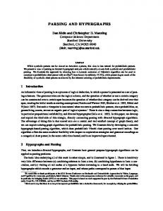
eventually has reduced the potential area of make-up drilling. Figure-3 shows the measured temperature at -2500’ elevation at pre-exploitation conditions, while Figure-4 shows the measured temperature at same depth as of mid 2010. The depth of -2500’ elevation is entirely below the boiling zone and is therefore representative of temperatures in the liquid reservoir. Several wells notably, Awi 7-3 and 8-6, are showing cooling in the liquid reservoir greater than 25 oF. Awi 7-3 and 8-6 wells were drilled in 2004 with expected initial temperature of 510 and 530 oF respectively, but were actually measured at about 465 - 477 oF (Figure-5). As indicated by tracer test results (Figure6) and geochemistry data, this large amount of cooling is attributed to thermal breakthrough from injection at the Awi 9 wells. Thermal degradation in other deep wells at Awi 7 and 8 locations are also taking place although at fairly moderate level. In average, enthalpy decline of other production wells at Awi 8 is 1.96 BTU/lb/year (Figure 7).
51 0
the production potential of the Salak field going forward. Based on preliminary project economics, it was confirmed that the production potential of the field could be increased through moving injection outside the proven reservoir boundary and allowing conversion of former infield injection areas with production potential such as Awi 9 to reduce or delay future make-up drilling.
47
0 440 43 43 0420
AWI-15
47 0
440
Figure 3 – Pre Exploitation Temperature distribution Frame 001 ⏐ 05 Jan 2011 ⏐
450
4 80
0 46
410 400
490
AWI-16
51
444 040 41 0
43
Figure 4 – Temperature distribution in 2010
0 4604 6 0 46
0 50 0 0 AWI-14 46 440 15-1ST 44 15-2OH 43 0 46 0 4 444050 6AWI-15 0 484070 45400 4 47 0
0
490
443 300
46 0
AWI-13
470 480
48
0
48 0
Utilizing wells at Awi 9 for long term brine injection is unlikely to be an optimum injection strategy primarily because it places the highest temperature part of the system at risk to injection breakthrough. Data from 15 years of exploitation reveal that the injection breakthrough has caused declining temperature and steam in some wells. Some portions of the deep reservoir have also experienced a considerable decline in temperature, which
AWI-1
AWI-2
51 0
510
Y
47 0
450 410 430
550
AWI-10
0
52 0
X TEMP
AWI-7
500
510
0 45
Figure 2: Historical brine injection to Awi 9 and 10 locations
Z
AWI-3
490
0 47 420 4 60 4 0 40020460 49 470 484050 10 4 0 AWI-8 43 0 405 4 20 0 46 600 51 48 480 4 520 AWI-11 AWI-9 550
47
470
430 0 0 46 47
0
550 540 530 520 510 500 490 480 470 460 450 440 430 420 410 400
Figure 5: Stabilized initial temperature at Awi 7-3 and 8-6 wells
Reformulating current injection strategy is one of element in the Salak Optimization Project. Selected strategies to be implemented include moving condensate injection from current infield location in West Salak to the the southeast area of Salak as well as to areas not connected to the reservoir. Two injection strategies were devised that represent increasing levels of injection displacement away from producers that can be combined: • Proximal Southeast Injection Strategy. In this strategy, 3000 kph (378 kg/s) of brine injection will be moved from Awi 9 to the proximal southeast location by 2012. The target wells for this injection are the redrilled and recompleted Awi-14/15 wells (see Fig 1). Brine injection at Awi 9 is reduced in the wells that have been established as having the greatest negative impact on the nearby producers. Awi 9-6 is considered the lowest priority due to its deep feed zone and minimal tracer returns (Figure 6) relative to the other wells. Placing the remaining western injection at Awi 9-6 is preferred strategy for converting some Awi 9 wells to production • Brine-out Injection Strategy. Here, another 1500 kph (189 kg/s) of brine injection from Awi 9 will be moved to areas not connected to reservoir in 2014
Figure 6: Recover tracers at Awi 8-6. Four different tracers were injected at Awi 9 wells
Figure 8: Historical evolution of discharge enthalpy Awi 8-1and its predicted evolutions under three different injection strategies.
Figure 7: AWI-8 Lumped Well Enthalpy Evolutions. Enthalpy decline rate is 2 BTU/lb/yr
3. RESERVOIR PERMORMANCE ANALYSIS Phasing out injection at Awi 9 has remained a high priority due to its proximity to main producer wells in West Salak as well as its own production potential.
The Salak reservoir simulation model has been used to evaluate field performance under injection scenarios described above. The results show that successful implementation of the 3000 kph move to the proximal SE would improve performance of production wells in Awi 7 and 8 locations. By completion of proximal southeast injection strategy, total fluid injection in the west will decrease by 4500 kph and net reservoir voidage will increase by 1500 kph. Besides mitigating the thermal breakthrough, it is expected that the steam cap will expand
dramatically as the liquid level in the reservoir decreases and eventually increase discharge enthalpy and deliverability of main production wells in Awi 7 and 8 locations. Figure-8 shows predicted enthalpy evolutions of a production well (Awi 8-1) under three different injection scenarios resulted from numerical simulation. Awi 8-1 well has three feedzones located at -735, -900’ and -1125’ elevation and they currently produce fluid from liquid reservoir. Cooling from injection in Awi 9 to those liquid feedzones will continue if current injection strategy (As-Is case) is maintained and will eventually cause the well to die in late 2012. Under proximal SE injection strategy, diverting 3000 kph of brine injection from Awi 9 to the proximal southeast location in late 2011 will dramatically decrease liquid level and expanding steam cap development in reservoir especially western part of the field. As a result, the first two feedzones will produce dry steam as indicted by a step increase of discharge enthalpy (to around 650 BTU/lb) by 2012. Implementing outfield injection strategy in 2014 by moving additional 1500 kph of brine from Awi 9 to an outfield injector will expand further the steam cap into the western part of Salak into the third feedzone at Awi 8-1 well. Therefore, Awi 8-1 will completely produce dry steam by 2016.
Figure 9: Initial Deliverability of Awi 9-7 Well from well testing interpretation
4. DELIVERABILITY OF WELLS AT AWI 9 Currently, there are seven good-permeability wells in Awi 9 pad with following status: • Two wells (Awi 9-1 and 9-7) are idle • Five wells (Awi 9-2, 9-3, 9-4 and 9-6) are active injectors In 2006, a long term flow test on Awi 9-1 well was conducted. This flow test showed that Awi 9-1 can sustain 100 - 110 kph of steam production (5.9 – 6.5 MWe) at commercial wellhead pressure for the entire testing period of 6 months. In the meantime, Awi 9-7, which was recently drilled (in 2009), highlights further the attractiveness of the Awi 9 area for production. Data from the completion test suggests that initial production capacity of this well at commercial wellhead pressure is 410 kph or 24.3 MWe (Figure 9). Besides steam production, drilling Awi 9-7 also successfully provided information about the potential upside for the undrilled area that has been kept as a buffer between production and injection areas (Figure 10). Awi 9-7 well encountered deep permeability below -3000 ft elevation and the highest temperature encountered so far in Salak ( 620 oF, see Figure 11)
Figure 10: Map of Awi 9-7 trajectory that drilled to the 1km2 of undrilled section of Salak reservoir, S/SE of Awi 9
Figure 11: Initial Temperature of Awi 9 Wells. Awi 9-7 is the hottest well in Salak field
The Salak reservoir model was used to forecast production potential from Awi 9 wells under three different injection scenarios mentioned above, which are shown in Figure 10. If performance of existing producers is consistent with simulated results, steam production from Awi 9 will be required to maintain
full power generation of 377 MW by 2013. Steam production will only be expected from Awi 9-1 and 9-7 if the current injection strategy is preserved. Implementing the proximal southeast injection strategy adds an almost 300 kph more, which will be achieved in 2017. Implementation of the brine-out injection strategy will provide some 200 kph more bringing the total to 820 kph by Reservoir simulation results have also been used as basis for surface facility design.
Figure 10: Forecasted deliverability of Awi 9 wells
5. PRODUCTION FACILITY DESIGN The conversion of Awi 9 is to be carried out in two stages with Awi 9-1 and Awi 9-7 put online as producers first as they are currently idle followed by most of the remaining Awi 9 wells at a later date. Steam from Awi 9 pad will be delivered to power plants Unit 1, 2 and 3 in West Salak. A number of options for bringing Awi 9 wells into production have been considered as part of facility design study. For all options considered, it has been assumed that produced fluid from Awi 9 wells will be 2-phase flow requiring separation into the steam and brine fractions. Steam flow would leave the Awi 9 pad via 36” pipeline. Separated brine will flow into a brine drum and then feed into the existing brine system on the wellpad via a level control valve to maintain the level in the vessel before discharge to injector wells. The brine drum is required to allow some hold up of liquid as a buffer to protect the separators against process variations. Three key decision parameters were investigated to identify design options which included: brine disposal to wellpad header or to a dedicated well, location of separator and brine drum and route of steam transfer pipeline to power plant Unit 1, 2 and 3. Furthermore, consideration was given to the future implementation of Outfield Brine strategy, which is quite likely to involve tieing into one of the existing brine lines connecting production pads (Awi 7 and 8) to Awi 9 injection wells and
extending it to new injection wells located at far west of reservoir boundary (Awi 18 or in its vicinity). All options of surface production facility for Awi 9 conversion are developed in such a way that Awi 9 brine can be diverted by gravity to an outfield disposal site if required. Developed options also consider potential drilling of new production wells in Awi 9 pad in the future. Table-1, Table-2 and Figure 11 describe ten design options for Awi 9 conversion. Due to minimum thermal breakthrough effect on the nearby production wells and to maintain flexibility on injection operation, Awi 9-6 will remain dedicated as an injector well.. Design considerations included hydraulic performance of the brine system under both normal operating and upset conditions (such as pump trip), system reliability, steam quality, suitability for both planned expansion and unforeseen future needs (future-proofing), ease of construction, impact on steam production from other pads due to backpressure effects in the steam system, initial capital cost and life-cycle cost. After careful evaluation, option 11 (current) and 12 (future upgrade) were selected. By locating separator and brine drum on a nearby pad 5 m above wellpad elevation and injecting brine directly into a dedicated injection well (Awi 9-6), this option allows for future drilling of new wells on Awi 9 pad and protects the separators and brine drum from flooding due to potential pressure transients in the brine headers. It also involves installation of the shortest length of steam pipeline along an accessible construction corridor and makes use of existing steam infrastructure for the final tie-in to the power plant.
6. CONCLUSIONS Conversion of injection areas with production potential such as Awi 9, has been a goal of the longterm resource management strategy for Salak field as a way to mitigate thermal breakthrough and reduce the number of make-up wells by using existing injection wells. Reservoir modeling was used to estimate the thermal recovery profile on the cooled off area as well as the production potential of former injectors. Predictive runs done with this model indicated that enthalpy recovery of neighboring producers from relocation 3000 kph of brine injection from Awi 9 to proximal southeast injectors will result in much better reservoir performance as compared to current injection strategy. This relocation will also result in use of former injectors at Awi 9 as producers. Further benefit of thermal recovery and production potential will be obtained by relocating additional 1500 kph of brine from Awi 9 to outfield injectors. Predictive runs were also use to develop options for surface production facility.
Table 1: Design options for disposing of produced brine into the Awi 9 header system Options 1 (Current) 2 (Future Upgrade)
Description • Separators and brine drum on platform 5m above well pad • New steam line from Awi 9 following Awi 9 access road to tie-in with existing Awi 11 steam lines at the road junction.
Table 2: Design options for disposing of produced brine into Awi 9-6 dedicated well Options 3 (Current) 4 (Future Upgrade)
Description • Separators and brine drum on platform 5m above well pad • New steam line from Awi 9 following Awi 9 access road to tie-in with existing Awi 11 steam lines at the road junction.
5 (Current) 6 (Future Upgrade)
• •
Separators and brine drum located on Awi 9 well pad Dedicated steam line to tie-in with scrubber manifold from Awi 9 following Awi 9 access road then via Awi 11 steam corridor.
7 (Current) 8 (Future Upgrade)
• •
Separators and brine drum located on Awi 9 well pad Dedicated steam line to tie-in with scrubber manifold from Awi 9 via brine corridor to WPS.
9 (Current) 10 (Future Upgrade)
• •
Separators and brine drum located on platform 5m above well pad. New steam line from Awi 9 following Awi 9 access road to tie-in with existing Awi 11 steam lines at the road junction.
11 (Current) 12 (Future Upgrade)
• •
Separators and brine drum located on platform 5m above well pad New steam line from Awi 9 following brine corridor and tying in at WPS bridge
Figure 11: Decision Tree for Surface Facility Design on Awi 9 conversion
References Acuna, J.A., Stimac, J., Sirad-Azwar, L., and Pasikki, R.G.: Reservoir management at Awibengkok geothermal field, West Java, Indonesia. Geothermics, 37, (2008), 332-346. Stimac, J., Nordquist, G., Aquardi, S., and SiradAzwar, L.: An overview of the Salak geothermal system, Indonesia. Geothermics 37, (2008), 300331. Nordquist, G.A.: Recommended well pad locations based on geophysical interpretations. Unpublished Chevron Report (2004). Rohrs, D., et al.: Salak Conceptual Model Update. Unpublished Chevron Geothermal Indonesia Report (2005). Kay, N., et al: AWI 9 Conversion – CPDEP Phase 2 Study. Unpublished Sinclair Knight Merz Report (2010).