Study of Static & Dynamic Simulation of Friction Stir Welding Process Mohd. Anees Siddiqui*, S. A. H. Jafri*, Shahnawaz Alam* Abstract In case of Friction stir welding (FSW) process, a spinning non- consumable tool is used to generate frictional heat in the work piece due to which joining occurs without melting of metal therefore friction stir welding is categorized as solid state joining process. A lot of experiments and research has been carried out in this technique for joining of similar and dissimilar aluminum alloys. Welding of steel and other similar metal is still a challenge for scholars and researchers. A part from experimental work related to study of friction stir welding, there is space to work on modeling & simulation of friction stir welding tool and process by using analysis software like ANSYS, Hyper Works, etc. The simulation work includes static and dynamic analysis. Through this article some light is put on the above aspects through the available literature. Static analysis of FSW is performed on different types of tool profiles which are modeled and analyzed in ANSYS for the condition of structural and thermal loadings. Dynamic analysis of FSW is performed on tool & work piece for obtaining residual stresses and temperature gradients along the weld line of the plates. In this case the pin of tool is neglected because of negligible heat generated through pin and the focus is only on the shoulder.
Keywords: Friction stir welding, Tool profile, Simulation, Static & Dynamic Analysis.
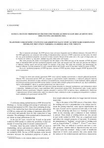
Introduction In FSW, a cylindrical shouldered tool with a profiled pin is rotated and plunged into the joint edges of metal plates which are clamped to prevent the joint faces from being separated. Frictional heat between the tool and the work pieces causes softening without melting which allows the tool to traverse along the weld line. The stirring action is performed by tool pin. On cooling, a solid phase joint is created between the work pieces. Because of various geometrical features of the tool, the material movement around
the pin can be complex.1 During FSW process, the material undergoes intense plastic deformation at elevated temperature, resulting in generation of fine and equaled recrystallized grains which results in good mechanical properties.1 FSW is considered to be the most significant development in metal joining in a decade and is a ‘‘green’’ technology due to its energy efficiency, environment friendliness, and versatility. As compared to the conventional welding methods, FSW consumes considerably less energy. No cover gas or flux is used, thereby making the process environment friendly.
Figure 1.The Principle of Operation of friction stir welding2 *
Department of Mechanical Engineering, Integral University Lucknow, INDIA E-mail Id:
[email protected]
© ADR Journals 2015. All Rights Reserved.
Siddiqui A et al.
38
Welding Parameters
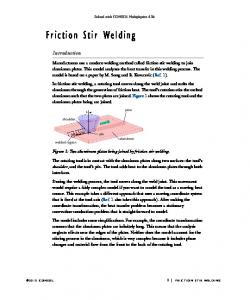
FSW involves complex material movement and plastic deformation which can be controlled by variation of several welding parameters which affect the quality of the welded joint. Welding parameters which are responsible for the performance and quality of the welded joint are as follows:11
Tool rotation rate (v, rpm) in clockwise or counter clockwise direction. Tool traverse speed (n, mm/min) along the line of joint. Angle θ of spindle or tool tilt with respect to the work piece surface. Target depth i.e. insertion depth of pin into the work pieces.
Figure 2.Diagrammatic Representation for Welding Parameter11
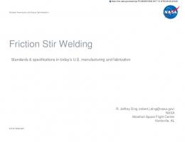
Tool Design Tool design influences heat generation, plastic flow, the power required, and the uniformity of the welded joint. Tool geometry such as probe length, probe shape and shoulder size are the key parameters because it would affect the heat generation and the plastic material flow.10 The tool is an important part of this welding process. It consists of a shoulder and a pin. Pin profile plays a crucial role in material flow and in turn regulates the welding speed of the FSW process. The shoulder generates most of the heat and prevents the plasticized material from escaping from the work- piece, while both the shoulder and the tool
pin affect the material flow. Friction stir welds are characterized by well- defined weld nugget and flow contours, almost spherical in shape, these contours are dependent on the tool design and welding parameters and process conditions used. The commonly used five pin profiles to fabricate the joints, in FSW are as follows (fig. 3):
Straight cylindrical Tapered cylindrical Threaded cylindrical Triangular Square pins
Figure 3.Schematic drawing of the FSW tool9
All India Seminar on Status of Welding in Research and Advancement in Analysis of Welded Structure 2015 • 20 – 21 Feb. 2015
39
Siddiqui A et al.
Literature Review on Simulation of FSW Process Static Analysis of Friction Stir Welding Tool Jeong-Luh Lin, et al. worked on “Stress analysis of FSW Tools Under Torsional and Bending loads”.3 In this study one of the tool is made from the same one- piece material with a probe of round pin attached to a scrolled shoulder, while the other is a two- pieces tool with a pin inserted into a
separate ring which acts like a shoulder and form similar pin on shoulder configuration like the first one. They analyzed two types of tools for strength, by comparing the stresses in these two tools, by subjecting them to the same loading conditions. According to Jeong-Luh Lin, et al., Ratio r/R of fillet radius r to the size of pin radius for the onepiece tool where its fillet radius at the junction of shoulder and pin shaft, it plays a critical role in tool strength as sharp geometric change and stress concentration locate at this corner.
Figure 4.Lateral bearing load acting and Stress contour on the one- piece tool due to bearing load (left) and Results obtained by Jeong-Luh Lin, et al. for influence of fillet radius (right)3
D. Raguraman, et al., worked on "Study of Tool Geometry on Friction Stir Welding of AA6061 & AZ61".4 They studied different tool geometry and analyzed for the identification of good weld through ANSYS. They focused on the steady state thermal analysis. Whenever a force is applied to a mechanical system, it will typically reach to a steady state after going through some transient
behavior. The length of the transient state will depend on the initial conditions of the system. So in case of friction stir welding the tool will be getting transient motion and then will reach a steady state. While welding the plates it is having transient conditions, but after relieving from the base metal it will experience a steady state temperature.
Figure 5.Results obtained by D. Raguraman, et al. for the Total heat flux with steady state thermal analysis for different tool geometry4
All India Seminar on Status of Welding in Research and Advancement in Analysis of Welded Structure 2015 • 20 – 21 Feb. 2015
Siddiqui A et al.
K. Rajesh Guptha, et al. worked on “Analysis of Friction Stir Welding Tools with Various Threaded Pin Profiles”.5 In their work, three tools with different pin shapes were modeled in CATIA and analysis was performed in ANSYS software for exploring stress distributions and displacement vector sum in the pin, at different speeds and
40
temperatures. The tool pin profiles considered for structural and thermal analysis are used in this study were cylindrical, conical, and frustum. The von mises stress distributions in pin profiles, displacement vector sum of the pin profiles, are obtained from ANSYS software and the pin with optimum strength was determined.
Figure 6.Results obtained by K. Rajesh Guptha, et al. for the Variation of displacement vector sum and stress distribution with rotational speed (above) & with temperature (below) in various threaded tool profiles5
Dynamic Analysis of Friction Stir Welding Thermo- mechanical model Prasanna et al., worked on “Finite element modeling for maximum temperature in friction stir welding and its validation”.6 They simulated Friction stir welding of material 304 L stainless steel and compared with the experimental results of Zhu et al. To maintain consistency, the
dimensions of the work piece, material properties, radius of the shoulder and pin, length of the pin, rotational speed, and welding speed used were considered same as Zhu et al. The results of the simulation were in good agreement with that of experimental results. The peak temperature obtained was 1,056.853°C, which was much less than the melting point of 304 L steel (1,450°C).
All India Seminar on Status of Welding in Research and Advancement in Analysis of Welded Structure 2015 • 20 – 21 Feb. 2015
41
Siddiqui A et al.
Figure 7.Finite element model of FSW, tool coordinate system and tool geometry6
Santhosh & Mahamad Mudabir, worked on “Thermomechanical Modeling and Experimental Evaluation of Friction Stir Welds of Aluminum AA6061 Alloy”.7 Their work involves physical understanding of friction stir weld joint formation and influence of weld process parameters from the combined complementary efforts of experimental examination and numerical modeling. The thermal histories and temperature distributions in the work piece during Friction stir welding (FSW) process involving the butt joining of aluminum AA6061-
T6 alloy was experimentally explored from the devised thermocouple layout to measure the temperature at different locations on the work piece. They carried out thermo- mechanical modeling of friction stir welding process by using simulation tool ‘Altair Hyper- works’ to evaluate the important physical aspects of FSW. They tested their simulation model with experimental results and found to be in good agreement with that of experimental results.
Figure 8.Surface Temperature contours during FSW obtained by Santhosh & Mahamad Mudabir7
All India Seminar on Status of Welding in Research and Advancement in Analysis of Welded Structure 2015 • 20 – 21 Feb. 2015
Siddiqui A et al.
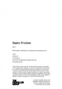
Abdul Arif, et al., worked on “Finite Element Modeling for Validation of Maximum Temperature in Friction Stir Welding of Aluminum Alloy”.8 They developed a finite element simulation with improved potential to predict temperature evolvement in aluminum
42
alloy. The developed finite element model was validated by comparing the simulation results with experimental data obtained by Feng et al. on AA 6061-T6 Aluminum alloy. They found the results of the simulation in accordance with the experimental results.
Figure 9.Results obtained by Abdul Arif, et al. showing modeled and experiment peak temperature as a function of distance from weld line8
Scope of Work through Simulation A lot of experiments and research has been carried out in this technique for joining of similar and dissimilar aluminum alloys. A part from experimental work for study of friction stir welding, there is huge gap to work on simulation and virtual experimentation of friction stir welding process by finite element method with utilization of available simulation tools such as Ansys, LsDyna, Abaqus, Forge, Comsol- Multiphysics & Hyperworks. Generally this technique is adopted by scholars before experiment because it saves both cost and time as simulation tools creates a virtual environment for experiment.
Conclusion The technique of simulation is generally adopted by the scholars for research because the experimental analysis of FSW needs the entire setup and it demands time and cost. The analysis of FSW by using ANSYS is techno commercially beneficial. But the crucial task in the analysis and simulation by ANSYS is to understand the real situation of the welding and types of physical and thermal loading on the tool and the work piece. In case of Static analysis, the problem is solved under static structural and steady state thermal module of the software. The motive of dynamic analysis of
the problems related to thermo- mechanical modeling requires transient structural and transient thermal modules of the ANSYS Software. From the above discussion on the basis of available literature related to modeling and simulation for static and dynamic aspects of Friction stir welding (FSW), it is obvious that there are several other aspects which are still to go through. Different tool profiles such as straight cylindrical, tapered cylindrical, square, triangular shape can be simulated and analyzed for several aspects. For this, tools of above mentioned profiles can be modeled by using modeling software such as Solid Works or CATIA and then they can be analyzed in ANSYS for the condition of frictional and thermal loading for different materials before going for experimentation.
References 1.
2.
3.
Mishra RS, Ma ZY. Friction stir welding and processing. Materials Science and Engineering Aug 2005; 50(1-2): 1-78. Sidhu MS, Chatha SS. Friction Stir Welding – Process and its Variables: A Review. International Journal of Emerging Technology and Advanced Engineering Dec 2012; 2(12): 275-79. Lin JL, Lin WB, Yang IH et al. Stress analysis of friction stir welding tools under
All India Seminar on Status of Welding in Research and Advancement in Analysis of Welded Structure 2015 • 20 – 21 Feb. 2015
43
4.
5.
6.
7.
Siddiqui A et al.
Torsional and Bending loads. WHAMPTONAn Interdisciplinary Journal 2007; 52: 3345. Raguraman D, Muruganandam D, Kumaraswamidhas LA. Study of tool geometry on friction stir welding of AA 6061and AZ61. IOSR Journal of Mechanical and Civil Engineering 2014: 63-69. Guptha KR, Sathish K, Kumar NJ. Analysis of Friction Stir Welding Tools with Various Threaded Pin Profiles. International Journal of Engineering Research and Applications Jan - Feb 2013; 3(1): 758-61. Prasanna P, Rao BS, Rao GKM. Finite element modeling for maximum temperature in friction stir welding and its validation. Int J Adv Manuf Technol 2010; 51: 925-33. Santhosh N, Mahamad MR. Thermomechanical Modeling and Experimental Evaluation of Friction Stir Welds of Aluminium AA6061 Alloy. International Journal of Engineering Research & Technology Aug 2013; 2(8): 1494-99.
8.
Arif A, Gupta SK, Pandey KN. Finite Element Modeling for Validation of Maximum Temperature in Friction Stir Welding of Aluminum Alloy. 3rd International Conference on Production and Industrial Engineering, CPIE- 2013, At NIT, Jalandhar, Punjab. 9. Elangovan K, Balasubramanian V, Babu BS. Predicting tensile strength of friction stir welded AA6061 aluminium alloy joints by a mathematical model. Materials and Design 2009; 30: 188–93. 10. Gopalakrishnan S, Murugan N. Prediction of tensile strength of friction stir welded aluminium matrix TiCp particulate reinforced composite. Materials and Design 2011; 32: 462–67. 11. Siddiqui MA, Jafri SAH, Bharti PK et al. Friction Stir Welding as a Joining Process through Modified Conventional Milling Machine: A Review. International Journal Of Innovative Research & Development Jul 2014; 3(7): 149-53.
All India Seminar on Status of Welding in Research and Advancement in Analysis of Welded Structure 2015 • 20 – 21 Feb. 2015