STUDY OF SYNCHRONOUS MOTOR ROTOR POSITION MEASURING METHODS Marek Čambál, Martin Novák, Jaroslav Novák Czech Technical University in Prague, Faculty of Mechanical Engineering, Department of Instrumentation and Control Engineering, Division of Electrical Engineering, Technická 4, 166 07 Prague 6, Czech Republic. E-mail:
[email protected],
[email protected],
[email protected]
Abstract -This paper presents the possibilities of synchronous motor rotor position measuring. Three possibilities of electronic circuits are discussed: direct position measurement using A/D converters, indirect position measurement with comparison and D/A converters and a measuring method based on phase error estimation. Key words – Measurements, Sensors, Permanent magnet motors.
1. INTRODUCTION
At the Department of Instrumentation and Control Engineering, Division of Electrical Engineering of the Czech Technical University, we are investigating the usage possibilities of synchronous motors with permanent magnets in the field of transportation. We are focusing our attention on these main areas: 1) Traction synchronous motor control 2) Electric power splitter control for hybrid drives 3) High speed synchronous motor control for car turbines In the first two areas, there are high demands for the quality of control as theirs regulation structure needs the information of rotor position to synchronize the inverter. Because of the high demands on speed and accuracy, we are not yet using the sensor less rotor position estimation. In the third group, besides the position measuring in the range of high RPM, we are also considering the use of fixed voltage/ frequency ration to power the motor or electronic commutation with sensor less position measuring. For rotor position measuring it is possible to use an incremental encoder or resolver. Incremental encoders have on theirs output a signal that can be easily evaluated and the resolution per one revolution is also sufficient. How ever, the range of RPM where they can be used is limited, they are not sufficiently robust and do not provide the absolute position information at all times. Some sensors are providing this useful information only once per revolution. The described disadvantage can be removed by a reference movement after the power µP sequence, whet the reference mark is used to set the zero position. This process is used in servos, but it is not possible to use it in traction motors and electric power splitters. A resolver requests a fixed frequency voltage source, mainly in the range of 5 – 20 kHz. The position measurement is not quite simple and needs a special electronic circuit. Resolvers are however sufficiently robust even for demanding applications, have a large RPM range, a sufficient resolution and provide the absolute position information in each time. For this reason, we are therefore
PDF created with pdfFactory trial version www.pdffactory.com
focusing on resolvers’ usage. We are using two pole resolvers with input signal frequency of 10 kHz and non contact signal transmission to the rotor. These devices are easily available on the market. The main problem is the revolver’s output signal processing for determining the measured position with sufficient resolution even by high RPM. For our application, we have therefore set the following goals: for the traction motor and electric power splitter 1000 positions per one revolution by maximum 3000 RPM, for turbine motor 1000 positions per revolution by maximum 50000 RPM. We are investigating the possibility of own electronic circuitry usage discussed in the following text, focusing on cheap and ordinary available parts and we are also using the special R/D based circuitry electronics.
2. DIRECT POSITION MEASUREMENT BY MEANS OF A/D CONVERTER
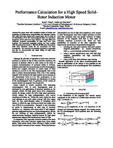
For evaluating the principle of this method we have at first build a simplified version of the circuit for usage with the resolver and output frequency of 2 kHz - fig. 1 K
RESOLVER
A8 2 kHz
EPROM AIN
WR
D0÷D6
A/D
8
7
A0÷A7
2,5V
SYNCHRONISATION
Fig. 1 Direct position measurement by means of an A/D converter The resolver’s rotor position measurement is based on one of the two output voltage sampling by means of an A/D converter. The synchronization signal for the 8 bit A/D is derived from the resolvers input signal. The A/D converter’s input voltage levels are in the range of 0 – 5 V. For this reason the reference voltage for the A/D conversion is not zero, but is shifted to the level of 2,5 V. The synchronized sampling method allows the output voltage sampling always at the same position of the input sinusoid. The sampled value is therefore dependent only on the mutual inductance of the coils i.e. the rotor’s position. The A/D output is an 8bit number, but this does not directly give the searched angle in the range of 360°, because the voltage is changing by a sinusoid and each single voltage value is occurring twice in the range of one revolution. For this reason, an additional bit for uniquely distinguishing the position where the two voltages have the same value is necessary. This bit is obtained by measuring the second
PDF created with pdfFactory trial version www.pdffactory.com
revolver’s output voltage polarity. Its level is changed to TTL level by means of a comparator, comparing this voltage level with zero voltage. By using the described process, we obtain 9 bit information that gives us the resolvers’ rotor position in the range of one single revolution. The obtained value is not linearly dependent on the rotor position and linearization is therefore done by means of a table stored in the EPROM memory. On its outputs, the signal is linearly changing with the input rotor position angle. The output values are only 7bit, resolving 128 positions, which is given by the used EPROM memory table construction. For the reason of low resolvers excitation frequency and the sampling only once per this signals period, this method does not allow the position measurement in the range of high RPM’s. At the present time, we are investigating this method’s usage directly in the synchronous motor control DSP. The used two-pole resolver is supplied to the rotor winding with the voltage having frequency of 10 kHz. A microcontroller is equipped with fast A/D converter having 80 ns conversion time. A/D conversion triggering is synchronized with the resolvers’ excitation voltage so that the conversion is carried out during the positive and negative voltage wave part of the resolvers’ output voltage. The computation of the absolute value of this sample follows. The zero level is shifted by 2,5 V of the converters reference voltage in the same way as in the previous application example. The A/D conversion triggering pulse is obtained by an external comparator processing the resolvers’ excitation voltage wave forms. The last bit information, distinguishing the signals’ polarity, is obtained by another comparator. All these signals are on the DSP’s parallel port input, in the DSP’s memory is placed a linearization table. For the synchronous traction motor, the PWM and control system computation frequency will be 5 kHz. When we consider the maximum RPM’s as 1500 min-1 it is necessary to evaluate 200 different positions per one revolution and for 150 RPM 2000 positions. Based on this assumption, we consider that this proposed approach will satisfy the demands of the field oriented synchronous motor control.
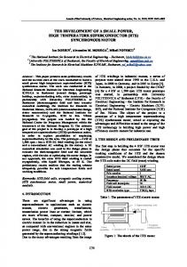
3. INDIRECT POSITION MEASUREMENT WITH COMPARISON AND D/A CONVERTERS The principle of this method is shown on fig. 2 K REF
RESOLVER
ϕn+1
X
D/A
n+1 8
K
µP
P1
K+1
10 kHz
P2
ϕn-1 X
K
n-1
D/A
D8
8 K-1
K
ABS
Fig. 2 Indirect position measurement with comparison and D/A converters
PDF created with pdfFactory trial version www.pdffactory.com
The measured position is evaluated continuously. Signals P1 and P2 on the µP output are corresponding with output signals of an incremental encoder. On the output ports n+1 and n-1 are available the values proportional to the previous and the following positions. These values are converted to analogue values with the D/A converters and multiplied with the resolvers excitation signal. The multiplied values are compared with the resolvers’ output voltage. When the next position is achieved, the corresponding comparator switches and the µP compute a new n+1 and n-1 positions. The information regarding the resolvers input signal polarity REF is used by the µP for resolving the positive and negative input voltage period. The second resolvers coil voltage ABS is used to determine the movement direction when the other voltage is near its maximum value and to obtain the absolute position after the system power up. The absolute position information is available in digital form at the output D8 of the µP. The presented measuring possibilities have been successfully tested with an 8bit D/A converter and ordinary available fast comparators. The biggest disadvantage is the insufficient sensitivity of the comparators because it is necessary to compare voltage with values near the comparators offset. To obtain sufficient resolution it is therefore necessary to use 12bit D/A converters and special precision comparators. 4. MEASURING METHOD BASED OF PHASE ERROR ESTIMATION The principle of this method can be described by following equations. The output voltage of the two stator’s coils is given as: u1 = U sin(ω ⋅ t ) ⋅ sin ϕ u 2 = U sin(ω ⋅ t ) ⋅ cos ϕ
(1)
Where U is the amplitude given by the excitation voltage and ϕ is the measured angle. By modifying the equations to the following form v1 = U sin(ω ⋅ t ) ⋅ sin ϕ ⋅ cos φ v 2 = U sin(ω ⋅ t ) ⋅ cos ϕ ⋅ sin φ
(2)
where φ is the last actually measured angle, we obtain after subtracting these equations v1 − v 2 = U sin(ω ⋅ t ) ⋅ (sin ϕ ⋅ cos φ − cos ϕ ⋅ sin φ ) = U sin(ω ⋅ t ) ⋅ sin(ϕ − φ )
(3)
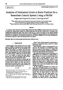
The output voltages u1 and u2 are sampled by means of A/D converters, processed through the above mentioned equations, the AC component U sinωt is removed and the difference ϕ-φ is computed. When a certain value of this difference is surpassed, a new actual value ϕ is computed. This measuring principle is used in a special integrated circuit available on the market. This circuit contains also the voltage source for supplying of the resolver and the position information is available in parallel, serial or incremental encoder simulation form. We used this circuit for the construction of an autonomous universal card – fig. 3. This card converts the position information into digital form, distinguishing 4096 position per one revolution. This card is composed of the power source, the main R/D circuit and a current amplifier to amplify the resolvers’ excitation voltage. This circuit uses the internal oscillator to synchronize the evaluation circuit. The circuits maximum output current is 100 µA so it needs amplification by an external amplifier. Based on
PDF created with pdfFactory trial version www.pdffactory.com
the schematic, the resolvers’ excitation voltage is generated in two branches and the output voltage is given by these two voltages difference, eliminating this way the DC component. The maximal input current of the used resolver is 50 mA with the effective voltage value 7V and frequency of 10 kHz. The card - microcontroller’s connection is assumed to transfer continuously the position information in the form of common incremental encoder’s signals, this means in relative form. This incremental encoder simulation if often directly supported in DSP timer modes and does not present an additional CPU load. After the microcontrollers start and at the predefined times, the absolute position information for the initial and continuous synchronization will be transfer by a serial channel. In addition, the resolvers or evaluation circuit fault is also transferred to the microcontroller.
Fig. 3 R/D converters autonomous universal card
5. CONCLUSIONS In the course of the development, we are using all these three mentioned methods, including the software realization of the first method by means of the motor’s control DSP. Because of the more complicated hardware and software implementation and the limited possibilities of using ordinary available parts for the first and third mentioned method we are at this time focusing our attention on the indirect position measurement with comparison and D/A converters usage method. How ever, the phase error method shows promising results and the usage of a special integrated circuit could significantly reduce the unit’s circuitry complexity and costs. The main advantage of this approach compared to the pure software implementation is the bigger resolution per one revolution, more prompt reaction and lesser control DSP load. The developed autonomous R/D card is build in a universal manner, allowing the different control units usage and the usage of this system in other devices requiring fast and accurate angular position information. 5. REFERENCES [1]RIPKA P. TIPEK A.: Master Book on Sensors, CTU-Czech Technical University in Prague. [2]Companies presentations SEW Euro drive, Texas Instruments, Atlas Copco, Analog Devices, Atas Náchod
PDF created with pdfFactory trial version www.pdffactory.com