Available online at www.sciencedirect.com
ScienceDirect Procedia CIRP 42 (2016) 46 – 50
18th CIRP Conference on Electro Physical and Chemical Machining (ISEM XVIII)
Study on the Effect of External Hydrostatic Pressure on Electrical Discharge Machining Tomohiro Koyanoa,*, Shodai Suzukia, Akira Hosokawaa, Tatsuaki Furumotoa a
Kanazawa University, Kakuma, Kanazawa, 920-1192, Japan
* Corresponding author. Tel.: +81-76-234-4711; fax: +81-76-234-4711. E-mail address:
[email protected]
Abstract This paper describes the influence of external hydrostatic pressure on material removal rate of electrical discharge machining (EDM). In EDM, because electrode materials and dielectric liquid are evaporated by arc plasma, gas bubbles are generated in the working gap. The machining gap is mostly occupied with gas bubbles during the machining process. In this study, machining was conducted under some external hydrostatic pressure from below to above atmospheric pressure in order to investigate the influence of gas bubbles on the material removal rate. EDM experiments were conducted on drilled holes. Machining results shows that the material removal per pulse in consecutive pulse discharges slightly decreased as the external pressure increased. This is probably because under the lower pressure, the boiling point of the electrode materials decreases. In addition, under optimal pressure, the feed of tool electrode was stable and the material removal rate was largest. This is because the sufficient large bubbles enhance the flushing of the dielectric liquid contaminated with debris particles and gas bubbles in the machining gap.
© The Authors. Publishedby byElsevier ElsevierB.V. B.V. This is an open access article under the CC BY-NC-ND license © 2016 2016 The Authors. Published (http://creativecommons.org/licenses/by-nc-nd/4.0/). Peer-review under responsibility of the organizing committee of 18th CIRP Conference on Electro Physical and Chemical Machining (ISEM Peer-review under responsibility of the organizing committee of 18th CIRP Conference on Electro Physical and Chemical Machining XVIII). (ISEM XVIII) Keywords: Electrical discharge machining; Gas bubbles; External hydrostatic pressure; Material removal rate
1. Introduction In electrical discharge machining (EDM), dielectric liquid is important because they prevents the reattachment of removed materials onto the electrode surface [1]. In addition, the dielectric liquid is important for cooling the machining gap [1]. Since electrode materials and dielectric liquid are evaporated by arc plasma, however, gas bubbles are generated in the working gap [1]. Ikeda [2] observed the oscillation of a gas bubble generated by a single pulse discharge with repeated expansion and contraction. It is widely assumed that the bubble oscillation enhance the flushing of debris particles and gas bubbles generated by the previous discharges because the boundary between the gas bubble and dielectric liquid expands rapidly. On the other hand, in the actual EDM process, it is expected that the machining gap is mostly occupied by gas bubbles, even though the electrodes are submerged in the dielectric liquid [1]. Kitamura et al. [3] observed the machining gap using an optically transparent SiC single crystal material as the electrode. They found that more than 80 % of the machining
gap was occupied by gas bubbles as expected. The machining gap was mostly occupied with gas bubbles after a few hundred discharges [4]. In the sinking EDM process, because the gas bubbles and dielectric liquid contaminated with debris particles impair the machining stability, jump flushing operation of the tool electrode is normally used in order to flush the gas bubbles and debris particles from the machining gap. Because the machining gap is occupied with the gas bubbles rapidly after machining starts, however, jumping cycle have to be shortened, resulting in the excessive machining time. On the other hand, because the gas bubbles rise owing to buoyancy and are ejected from the machining gap, this causes the dielectric liquid to flow [5]. Hence, gas bubbles may enhance the flushing of debris particles and cooling of electrodes. As described above, gas bubbles are considered to have a significant influence on the machining characteristics of EDM. Hiroi et al. [6] observed the quantity of gas bubbles in the machining gap using ultrasonic waves transmitted through the machining gap. They found that about 50 % of the machining gap was occupied by gas bubbles, and the quantity of the gas
2212-8271 © 2016 The Authors. Published by Elsevier B.V. This is an open access article under the CC BY-NC-ND license (http://creativecommons.org/licenses/by-nc-nd/4.0/). Peer-review under responsibility of the organizing committee of 18th CIRP Conference on Electro Physical and Chemical Machining (ISEM XVIII) doi:10.1016/j.procir.2016.02.184
47
Tomohiro Koyano et al. / Procedia CIRP 42 (2016) 46 – 50
bubbles affected the material removal per pulse in consecutive discharges. Masui et al. [7] carried out EDM processes under hydrostatic pressures of 0.01MPa to 0.1 MPa in order to enhance the flushing effect of the gas bubbles. They found that the discharge number between jump flushing motions of the tool electrode increased as the hydrostatic pressure decreased since gas bubble expansion with lower pressure enhanced the flushing of gas bubbles and debris particles. Although they investigated the discharge number, however, the influence of the vacuum environment on the material removal rate was not described. We carried out EDM experiments under some external hydrostatic pressure from below to above atmospheric pressure in order to investigate the influence of gas bubbles [8]. The quantity of gas babbles generated by a single discharge varies mainly according to the discharge energy. Since the discharge energy affects the machining characteristics such as the material removal rate, however, it is difficult to investigate only the influence of the gas bubbles on the machining characteristics. The variation of the external hydrostatic pressure enables the investigation of the influence of gas bubbles without changing the discharge energy. Experimental results showed that the material removal in a single pulse discharge increased as the external pressure decreased because the boiling point of the electrode materials decreased under the lower pressure. In addition, results of sinking EDM suggests that the gas bubbles are significantly important for the machining stability because they enhance the flow of the dielectric liquid. In this work, in order to clarify the influence of bubbles on the machining characteristics further, the gas bubbles ejected from the machining gap were observed in consecutive pulse discharges under hydrostatic pressures of 0.02MPa to 0.3MPa. In addition, sinking EDM was carried out by changing the thickness of the workpiece. Then the influence of the hydrostatic pressure on material removal per pulse in consecutive pulse discharges and the material removal rate was investigated. 2. Observation of gas bubbles ejected from the machining gap
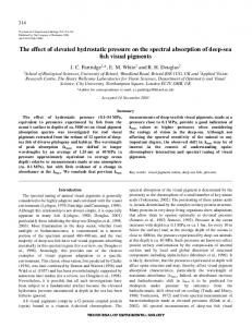
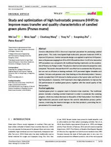
was connected to the Z-axis of a laboratory ED machine through a bush. Figure 1 (b) shows the experimental setup for observation of gas babbles ejected from the machining gap. Two transparent acrylic plates were placed at the sides of the chamber. Light was emitted from the one side, and the machining gap was observed from the other side by a highspeed camera (Photoron, FASTCAM SA5). Table 1 shows the machining conditions. The tool electrode was a copper rod with a diameter of 2 mm, and the workpiece was a stainless steel (AISI 304) plate. The external pressure was changed from 0.02 MPa to 0.3 MPa in order to change the volume of the gas bubbles generated by the discharges. The atmospheric pressure is 0.1MPa. The tool electrode was fed to the workpiece, and discharges were generated consecutively between the tool electrode and the workpiece under the different external pressure. Then the gas bubbles ejected from the machining gap were observed when the machining depth was shallow.
Pressure gauge
Z-axis
Valve
Vacuum pumps Bush Regulator
Shaft
Air compressor
Tool electrode Oil Chamber
Workpiece
(a) Machining equipment Z-axis Acryl Tool electrode Light source
High-speed video camera
Acryl
Workpiece
(b) Experimental setup for observation by high-speed camera Fig. 1. Experimental setup.
2.1. Experimental Setup The gas bubbles ejected from the machining gap were observed in consecutive pulse discharges using a high-speed camera. Figure 1 (a) shows the machining equipment. Machining was conducted in a chamber. When the dielectric liquid was pressurized, compressed air was supplied from an air compressor through a regulator which can control the pressure in the chamber. When the pressure was reduced, a vacuum pump was connected to the chamber, and the pressure was controlled by controlling the flow rate thorough a valve connected to the chamber. Experimental results [8] showed that as the hydrostatic pressure decreased, oscillation period and the maximum bubble diameter during oscillation increased. In addition, the steady state value of the bubble diameter after oscillation decreased as the hydrostatic pressure increased. A tool electrode was placed at the end of a linear shaft. The shaft
Table 1. Machining conditions. Pulse generator Open circuit voltage (V) Discharge current (A) Discharge duration (μs) Pulse interval (μs) Tool electrode Workpiece Polarity Dielectric liquid External pressure (MPa)
Transistor type (Iso pulse) 110 4.5 50 420 Copper (Φ2mm) Stainless steel (AISI 304) Tool electrode (+), Workpiece (-) EDM oil 0.02, 0.1, 0.3
48
Tomohiro Koyano et al. / Procedia CIRP 42 (2016) 46 – 50
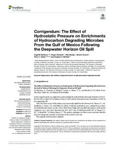
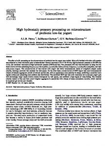
2.2. Observation results Figure 2 shows the observation results under the different external pressure. The machining depth was shallow, only a few micrometers. Figure 2 (a) shows the tool electrode and the workpiece before machining. The dark region of figure 2 (b), (c), and (d) denotes the gas bubbles and debris particles in the EDM oil. Under 0.3MPa, the gas bubbles and debris particles around the electrodes were less than those under the other lower pressures. The gas bubbles and debris particles increased with decreasing the external pressure because the volume of the gas bubbles was larger under the lower pressure. In addition, it was observed that the gas bubbles were ejected from the machining gap with rapid movements under lower pressure. This is because the maximum bubble diameter is larger when the bubble expands under the lower pressure [8], and the bubble expansion enhances the flushing of the debris particles and the gas bubbles generated by previous discharges. In addition, because the gas bubbles rise owing to buoyancy and are ejected from the machining gap, this causes the dielectric liquid to flow. Hence, it is expected that the gas bubbles enhance the flushing of debris particles and cooling of electrodes.
material removal rate was obtained by dividing the measured removal volume by the machining time. The tool electrode was a copper rod with a diameter of 2 mm, and the workpiece was a stainless steel (AISI 304) plate. It is considered that the bubbles are hardly ejected from the machining gap when the machining depth becomes deep. Therefore, workpiece of thickness 1mm and 3mm were used, and the influence of the workpiece thickness on the material removal rate was investigated. The external pressure was changed from 0.02 MPa to 0.3 MPa. The reference servo voltage was changed from 6 V to 85 V in order to change the discharge frequency. The other machining conditions were similar to those described in table 1. The machining was conducted without the jump motion of the tool electrode. In addition, the discharge number was counted during machining in order to obtain the material removal per pulse in consecutive discharges at the reference servo voltage of 85V. The discharge number was measured by detecting the rise of working gap voltage with a threshold value of 85V. Then, the removal volume per pulse in consecutive discharges was obtained by dividing the removal volume of the workpiece by the total number of discharges counted during machining. 3.2. Experimental results
Workpiece
(a) Before machining
1mm
Bubbles and debris particles
(b) 0.3MPa
1mm
(c) 0.1MPa
1mm
(d) 0.02MPa
1mm
Fig. 2. Observation of gas bubbles ejected from machining gap.
3. Influence of external pressure on material removal rate 3.1. Experimental setup Sinking EDM experiments were carried out on drilled holes in order to investigate the influence of external hydrostatic pressure on the machining characteristics. The same equipment shown in figure 1 (a) was used. Through holes were machined on the workpiece, and the material removal rate was measured and compared for different external hydrostatic pressures. The
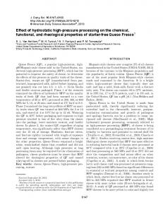
Figure 3 shows the relationship between the material removal per pulse in consecutive discharges and external hydrostatic pressure with the reference voltage of 85V. When the reference voltage was 85V, the short circuits and abnormal arc hardly occurred because the machining was stable due to the low discharge frequency. Material removal per pulse in consecutive discharges slightly decreased as the external pressure increased. This is probably because under the high pressure, the boiling point of the electrode materials increases [9]. Because the material removal per pulse in consecutive discharges was almost the same quantity regardless of the external pressure, however, it is considered that the material removal rate described later was affected mainly by the influence of the gas bubbles in the machining gap. Figure 4 shows the relation between the material removal rate and reference servo voltage with the workpiece of 3mm thickness. Each plot means an average value of the material removal rate of several machining. Lower reference servo Material removal per discharge [㽢10-6 mm3]
Tool electrode (Φ2mm)
3.5 3 2.5 2 1.5
Discharge current: 4.5A Discharge duration: 50μs Tool : copper (Φ2mm) Workpiece: stainless steel (t3mm) Reference servo voltage: 85V
1
0.5 0 0
0.1
0.2
0.3
0.4
External hydrostatic pressure [MPa] Fig. 3. Material removal per pulse in consecutive discharges.
49
Tomohiro Koyano et al. / Procedia CIRP 42 (2016) 46 – 50
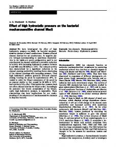
Discharge current: 4.5A Discharge duration: 50μs Tool : copper (Φ2mm) Workpiece: stainless steel (t3mm)
10
12 Material removal rate [㽢10-3mm3/s]
Material removal rate [㽢10-3mm3/s]
12
0.06MPa 8 6
0.02MPa 4
0.1MPa 0.3MPa
2
0
10
20
30
40
50
60
70
80
90 100
Reference servo voltage [V] Fig. 4. Material removal rate (workpiece thickness: 3mm)
3
0.02MPa 0.1MPa
2.5 Feed of Z-axis [mm]
0.02MPa 0.1MPa
8
0.3MPa
6 4
Discharge current: 4.5A Discharge duration: 50μs Tool : copper (Φ2mm) Workpiece: stainless steel (t1mm)
2 0
0
0.3MPa
2 1.5
Discharge current: 4.5A Discharge duration: 50μs Tool : copper (Φ2mm) Workpiece: stainless steel (t3mm)
1 0.5 0 0
500
1000
1500
2000
2500
3000
Machining time [s] Fig. 5. Comparison of feed of Z-axis (reference servo voltage:61V) 0.02MPa
3 0.06MPa
0.1MPa
2.5
Feed of Z-axis [mm]
0.06MPa
10
2 1.5 Discharge current: 4.5A Discharge duration: 50μs Tool : copper (Φ2mm) Workpiece: stainless steel (t3mm)
1 0.5 0 0
500
1000
1500
2000
2500
3000
Machining time [s] Fig. 6. Comparison of feed of Z-axis (reference servo voltage:24V)
voltage resulted in increase of material removal rate due to the increase of discharge frequency. However, after the peak, lowering the reference servo voltage lead to the decrease of the material removal rate because the short circuit and abnormal arc occurred frequency due to the high discharge frequency. The maximum material removal rate was lower under 0.3 MPa than those under the other pressures. Figure 5 shows the examples of the feed of Z-axis at the reference voltage of 61V. While the
0
10
20
30 40 50 60 70 80 Reference servo voltage [V]
90 100
Fig. 7. Material removal rate (workpiece thickness: 1mm)
machining depth was smaller than 1mm, the feed of Z-axis was stable regardless of the external pressure. When the machining depth was deeper than 1.5mm, however, since the gas bubbles and debris particles were hardly ejected from the machining gap, the Z-axis retracted frequently under 0.3MPa due to the short circuits and abnormal arc. On the other hand, the maximum material removal rate of 0.06MPa was higher than that of 0.1MPa as shown in figure 4. This is because the large bubble caused the dielectric liquid to flow, enhancing the flushing of debris particles and cooling of electrodes. However, the material removal rate of 0.02MPa was smaller than that of 0.06MPa. Figure 6 shows the examples of the feed of Z-axis at the reference voltage of 24V. When the machining depth was larger than 1.5mm, the feed speed of the Z-axis under 0.02MPa was smaller than that under 0.06MPa because the Z-axis retracted frequently due to the short circuit. This is probably because the overly large bubble occupied the machining gap, resulting in the unstable machining. In addition, it is known that the material removal caused by a single discharge increases when the discharge is ignited in oil compared to that in air [10]. This is because the expansion of the plasma was hindered by the inertia of the oil [11, 12], which results in the higher heat flux at the discharge spot. Under lower pressure, because the gas bubbles occupied the machining gap, the discharge tended to occur in air. This might be other reason why the material removal rate was lower under 0.02MPa. Nevertheless, these results indicate the gas bubbles have a significant influence on the machining characteristics of EDM. It is considered that when the bubbles are small under high external pressure, the flushing effect is eliminated because the expansion and contraction of the bubble are smaller. In addition, because the buoyancy of the gas bubble is less owing to the small bubble volume, the bubble is difficult to be ejected from the machining gap, which prevents the flushing of debris particles and cooling of the electrodes. On the other hand, under the low external pressure, overly large bubbles occupy the machining gap, which results in unstable machining. Based on these results, a sufficiently large gas bubble is important for machining stability because the bubbles cause the dielectric liquid to flow, and enhance the flushing and cooling of electrodes. Figure 7 shows the relationship between the material removal rate and reference servo voltage with the workpiece of
50
Tomohiro Koyano et al. / Procedia CIRP 42 (2016) 46 – 50
1mm thickness. The maximum material removal rates under every pressure were higher than those with 3mm thickness workpiece because the machining was stable due to the lower machining depth. Unlike the result of 3mm thickness workpiece, the material removal rates at 0.02 MPa, 0.06MPa and 0.1 MPa were almost equivalent. This is probably because gas bubbles were easily ejected from the machining gap even though the large amount of gas bubbles or the small amount of gas bubbles were generated due to the small aspect ratio of machined hole. These results shows that the material removal rate can be increased by setting the external pressure at an optimal value especially under the conditions that the gas bubbles are difficult to be ejected from the machining gap. 4. Conclusions In this paper, in order to clarify the influence of gas bubbles, sinking EDM was carried out on drilled holes under some hydrostatic pressure. High-speed camera observation of gas bubbles ejected from the machining gap in consecutive discharges showed that the gas bubbles were ejected from the machining gap with rapid movements under lower pressure. Experimental results of the sinking EDM showed that material removal per pulse in consecutive discharges slightly decreased as the external pressure increased. This is probably because under the lower pressure, the boiling point of the electrode materials decreases. The material removal rate was increased by setting the external pressure at an optimal value especially when the machining depth was deep. This is because the sufficiently large bubbles enhanced the flow of the dielectric liquid.
Acknowledgements This research was financially supported by a research grant from Mitutoyo Association for Science and Technology (MAST). References [1] Kunieda M, Lauwers B, Rajurkar KP, Schumacher BM. Advancing EDM through fundamental insight into the process. Annals of the CIRP. 2005; 54/2:64-87. [2] Ikeda M. The movement of a bubble in the gap depending on the single electrical discharge (first report). Journal of The Japan Society of Electrical Machining Engineers. 1972; 6/11:12-26 (in Japanese). [3] Kitamura T, Kunieda M. High-speed imaging of EDM gap phenomena using transparent electrodes. Procedia CIRP. 2014; 6:314-319. [4] Kitamura T, Kunieda M. Observation of relationship between bubbles and discharge locations in EDM using transparent electrodes. Precision Engineering. 2015; 40:26-32. [5] Kunieda M, Masuzawa T. A fundamental study on a horizontal EDM. Annals of the CIRP. 1988; 37/1:187-190. [6] Hiroi M, Imai Y, Nakano M. Observation of quantity of bubbles in electrical discharge machining gap. Journal of The Japan Society of Electrical Machining Engineers. 2000; 34/76:18-25 (in Japanese). [7] Masui K, Sone T, Sato Y, Hatanaka S. EDMing under reduced pressure, Die and Mould Technology. 1995; 10/7:126-127 (in Japanese). [8] Koyano T, Hosokawa A, Suzuki S, Ueda T. Influence of external hydrostatic pressure on machining characteristics of electrical discharge machining. Annals of the CIRP. 2015; 64/1:229-232. [9] Hildebrand JD. The vapor pressures of liquid metals. Jounal of the Americal Chemical Society. 1918; 40/1:45-49. [10] Yoshida M, Kunieda M. Study on the distribution of scattered debris generated by a single pulse discharge in EDM processes. International Journal of Electrical Machining. 1998; 3:39-46. [11] Kitamura T, Kunieda M. Clarification of EDM gap phenomena using transparent electrodes. Annals of the CIRP. 2014; 63/1:213-216. [12] Kojima A, Natsu W, Kunieda M. Spectroscopic measurement of arc plasma diameter in EDM. Annals of the CIRP. 2008; 57/1:203-207.