International Archives of the Photogrammetry, Remote Sensing and Spatial Information Sciences, Volume XL-7/W1, 3rd ISPRS IWIDF 2013, 20 – 22 August 2013, Antu, Jilin Province, PR China
SUB-APERTURE FOCUSING ALGORITHM OF GEOSYNCHRONOUS SAR Yun Zhang a, Hongbo Li a, Huizhi Xu b, Bin Hu a a
School of Electronic Information Engineering, Harbin Institute of Technology, Harbin, China
[email protected] b School of Transportation Engineering, North East Forestry University, Harbin, China Commission VII WGVII/6
KEY WORDS: High resolution, Algorithm, Synthetic aperture radar, Remote sensing
ABSTRACT: Synthetic Aperture Radar (SAR) on the geosynchronous orbit has the advantage in remote sensing, with high resolution to provide a large coverage in a short visit time. the space-variant coverage and range-azimuth couple of GEO SAR are required to compensate, using the electrical beam steering, the irregular data acquisition can be convert to classical SAR modes, such as stripmap, spotlight, sliding spotlight, and terrain observation by progressive scans (TOPS) SAR, the dopper analysis of these work modes of SAR have been studied. Based on deramping processing and improved subaperture chirp scaling algorithm, a novel focusing approach is presented in this paper, whose performance is determined by the work mode, data acquisition and the deramping processing. Data of each mode can be focused by utilizing this presented approach with the information of subapterture centroid time and range rotation center. Simulation results are presented to validate the analysis of the proposed approach. 1. INTRODUCTION Recently, low-earth orbit (LEO) SAR systems, such as TerraSAR, Radarsat and COSMO-skyMed, play an important role in remote sensing, but the key limitation of low-earth orbit SAR is the difficulty to providing the quick revisit time and the wide illuminated area at the same time. Even for the satellite constellations, like COSMO-skyMed, which use the distributed satellite to reduce the repeat period, also provide the large area imaging in a few days. However, for specific application, such as the monitoring of disaster, water fluid survey, soil moisture survey, and oil reservoirs, it is necessary to have geography information in a few hours. SAR in geosynchronous orbit, presented by Tomiyasu[1], has significant advantages over conventional LEO SAR, which runs the same cycle and Earth's rotation period, the observation range is conducive to continuous real-time monitoring with the short revisit cycle. Research literatures of GEO SAR provide disaster areas monitoring in the range of several hours daily [2]. The most representative study on GEOSAR system was introduced Cranfield University Aerospace Research Center and NASA's Jet Propulsion Laboratory respectively, involving in the orbit selection, launch system, beam forming, antenna designing, etc.[3], As for the signal characteristic, resolution calculation, and imaging algorithms, there is a little related literature on GEO in range and azimuth is serious, combined with the curve trajectory GEO SAR model, not the linear trajectory[4-9], even the atmosphere impact on the SAR focusing need to consider[10]. Furthermore, the doppler phase history become complex with the high order phase error, and the nonzero-Doppler centroid and the nonlinear varied FM rate are caused by Earth’s rotation and the elliptical orbit, leading to azimuth ambiguities and degradation of imaging performance, with the radar echo approximated a non-stationary signal or polynomial phase signal varied with illuminated time, which increase the difficulty of SAR processing. And, the doppler effect by the changing of orbit satellite was introduced, which cause the quality of SAR image deteriorated, although the coherence time. A new subaperture imaging algorithm suited to
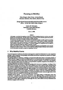
GEO SAR was proposed in this paper, with analysing the coverage in GEO SAR, the linear Doppler phase error and the high-order phase error caused by the curve trajectory model and the Doppler phase history, the full aperture time was divided in different duration of coherence time, to obtain different illuminate mode on the ground, and the linear trajectory approximation of subaperture echo is acquired by the interpolation. Deramp processing was introduce to transform the time-frequency relationship of different illuminate modes to the simple form, and the compensation of Doppler phase was introduced. 2. GEO SAR MODE 2.1 GEO SAR Coverage Analysis GEO SAR is new microwave remote sensing radar, which is located on geosynchronous orbit from the long range (about 36578km) to the earth’s surface. It can provide a large coverage, and reduce the visit time, but cost great transmitter power with weak received echo. Furthermore, its track is a “figure 8” located symmetrically about equatorial plane, as shown in the Figure 1. It should be noted that with a greater inclination angle, the earth can be imaged up to the higher latitudes, the relative satellite velocity increases and need greater power. As shown in the Figure 1, the trajectory of GEO SAR is illustrated. GEO SAR has advantage in coverage, the long integration time and large observation swath. But new challenges to SAR system design and signal processing is needed to put forward. Considered Earth centred rotation, the longitude and latitude variation from the nominal position of the satellite, coverage of the GEO SAR is shown in the Figure 2. At different position, the beam coverage of radar and the velocity are different, the doppler centroid residual varies (especially the point locates in the area of A, B, C, D), the range migration is deduced. So the target point spread function are no longer the same mode in the ground plane, the scattering properties may not remain, and the image degradation is therefore impossible to be avoided by the traditional SAR focussing method.
This contribution has been peer-reviewed. The peer-review was conducted on the basis of the abstract.
205
International Archives of the Photogrammetry, Remote Sensing and Spatial Information Sciences, Volume XL-7/W1, 3rd ISPRS IWIDF 2013, 20 – 22 August 2013, Antu, Jilin Province, PR China from radar, then the density of footprint varies. Combined with the electrical beam steering, the irregular illumination of radar converts to conventional SAR modes. With the zero-doppler centroid control method based on phase scan [6], it can compensate the doppler shift induced by earth’s rotation and the GEO SAR’s elliptical orbit. After the compensation, the complexity of focussing algorithm can be reduced. Here, give the analysis of some targets in especial area.For example, the target in the area of A, with the electrical beam steering control, the quasi terrain observation by progressive scans (TOPS) mode of SAR will complete. For the motion of satellite approximates linear, targets in the area of B receive the microwave from Strip mode of SAR. And targets in the area of C and may be work under the spotlight or sliding spotlight mode of SAR, Respectively shown in the Figure 4 (a), (b), (c) and (d). In the mode of a spotlight, sliding spotlight or TOPS mode, the electrical beam of steering is controlled to point to a fix point, namely, the rotation center, that is O’ in the Figure 4. As SAR platform move along the geosynchronous orbit, the closet distance from scene center (the point O) to the GEOSAR trajectory is Rc, and the closet distance is R ref . from rotation center to the GEOSAR trajectory. Assuming the velocity of GEO SAR is vs , the instantaneous slant range is
Figure 1. Orbit and ground track of GEO SAR satellite
A
B
C D
R(t ) Rc ( x vs t ) 2 2
Figure 2. Coverage of GEO SAR satellite
And the projecting velocity of the main beam on the ground is (2) v vs /
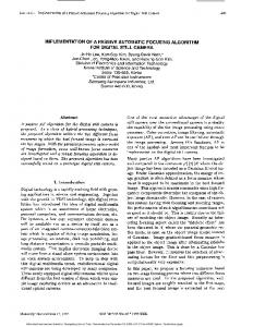
2.2 Doppler history analysis Due to the Earth’s rotation and the elliptical orbit, and the curve trajectory, the complexity of space geometry makes nonlinear coupling between range and azimuth, meanwhile the variation of slant range is described by a quadratic polynomial, that is, signal from target’s scattering is approximated a non-stationary signal or polynomial phase signal. According to the Doppler variety during the long synthetic aperture time, the Doppler centroid and the FM rate varied, shown in the Figure 3.Here, the GEO SAR system was simulated, assuming the orbit altitude of GEO satellite is 35786km, orbital inclination is 60 , the right ascension of ascending node is 105 , incident angle of radar is 30 , and the carrier frequency is 5.6GHz. The Doppler centroid and FM rate of chirp echo in azimuth changed with the attitude and the position of GEO SAR, the polynomial model is employed in SAR focussing processing accompanied by the range migration correction (RMC) function, the azimuth matched filter, phase error compensation of linear, quadratic, high-order is considered. Meanwhile, high precision Doppler parameter estimation algorithms would be investigated. 4
1.5
x 10
Where,
Rref Rref Rc
for the TOPS mode,
O
for the
far
Rc
Rc
O’ near
O far
(a) TOPS mode
(b) stripmap mode
5
O’
0
0.5
Fm rate(Hz/s)
Doppler Centroid(Hz)
Rref Rc
near Rref
-5
0
Rref
-10 -15
Rc
O
-20
O
-0.5
-25 -1
Rc
-30 -35 0
Rref
sliding spotlight mode. Generally, the resolution of the TOPs and sliding spotlight mode is improved by the factor approximated as 1/ from spotlight mode.
1
-1.5
(1)
50
100
150 200 250 orbit angle
300
350
400
0
(a) doppler centroid vs orbit angle
50
100
150 200 250 orbit angle
300
350
400
(b) FM rate vs orbit angle
Figure 3. Doppler varied vs Argument of latitude 2.3 Beam Steering Control Mode In this section, this paper shows the geometry of the nadir ground track and the beam illumination in the Figure 2, the trajectory of the beam velocity is varying with the orbit of GEO SAR, and the targets on the ground collect different energy
(c) spotlight mode
(d) sliding spotlight mode
Figure 4. Beam steering of the different SAR modes A chirp modulation of the transmitted pulse is assumed as
j 2 ( fc 1 t 2 ) 2 s ( , t ) rect e T p
This contribution has been peer-reviewed. The peer-review was conducted on the basis of the abstract.
(3)
206
International Archives of the Photogrammetry, Remote Sensing and Spatial Information Sciences, Volume XL-7/W1, 3rd ISPRS IWIDF 2013, 20 – 22 August 2013, Antu, Jilin Province, PR China
1 0
Where, rect(u )
u 12 , u 12
2-D spectrum by the Fourier transform operator, the azimuth spectrum is approximated linear time-frequency relationship. Define the frequency deramp function is
f c is the transmit frequency
H ramp e
Tp is the width of pulse
Where, ramp
is the chirp rate. The receive baseband signal of appoint located at (x, R(t)) is described as follows 2
2 R (t ) 2 R (t ) 2 R (t ) c j 4 j (4) rect t t 0 e c e s r ( , t ) Arect T T p s Where, c is the speed of light = the wavelength of SAR t 0 = the center illuminated time Ts Rc ( Rref Rc ) 2 x 2 ) /( Rref Rc ) 2 v ,is synthetic time.
After range compression, the range frequency and the azimuth frequency, that is 2-D spectrum, is shown in the Figure 5, ccorresponding to the different mode of SAR in the Figure 4. The difference in the 2-D spectrums between the spotlight, sliding spotlight or TOPS mode and stripmap mode is the supporting area or the occupied rang of the azimuth frequency band. During the data acquisition, the azimuth bandwidth of the spotlight, sliding spotlight or TOPS increase. Using the deramping processing, the time-frequency relationship can be rotated, and is similar to the 2-D spectrum of extended stripmap mode[11].
2 /( R ref ) ,
j
(3)
it is the deramp chirp rate.
Multiplied by the deramp function in the Doppler domain, the linear variation of instantaneous Doppler centroid is removed. After deramping processing compensation, the data support in time-frequency is extend, the filtering is employed to reduce it, and Doppler centroid shift is needed. 3.2 SubAperture Focussing Algorithm The proposed focussing processing is a improved subaperture Chirp Scaling algorithm, whose flow diagram was shown in the figure 6. After deramping processing, the echo signal is carried in the azimuth dimension by Fourier transform as the traditional Chirp Scaling algorithm, then it is multiplied with the Chirp Scaling factor to get a new migration curves. The second phase factor is designed to do RCM and the Range Compression. raw Deramp processing
Calculate by the R ref
Azimuth FFT
1st phase function (Chirp Scaling)
f azimuth
f azimuth
2 ramp
Range FFT
t
t
2nd phase function (RCM and RC) Range IFFT
(a) TOPS mode f azimuth
Subaperture1
(b) stripmap mode f azimuth
(c) spotlight mode
AzimuthIFFT
t
t
Subaperture2
3. SUBAPERTURE FOCUSING ALGORITHM According to the Earth’s rotation, the elliptical orbit, and the long aperture time, an effective sub-aperture GEOSAR segmentation method was presented, and the processing algorithm includes three steps: the azimuth frequency deramping processing, sub-aperture CS processing and the azimuth spectrum combination processing. 3.1 Doppler Pre-processing From the section 2, as GEO SAR move at different position, after antenna steering control, point data acquisition corresponds to different SAR mode collection. Convert it to the
Subaperture N AzimuthIFFT
De-rotation
De-rotation
Azimuth FFT Phase function (AzimuthCompression SCR,weighting)
Azimuth FFT Phase function (AzimuthCompression SCR,weighting)
(d) sliding spotlight mode
Figure 5.The Doppler time-frequency diagram of SAR modes
…
Combination
Subaperture Doppler centroid
Azimuth IFFT Image
Figure 6. Flow diagram of subaperture focusing processing The full aperture data in the azimuth spectrum is divided in to several sub bands by bandpass filter, corresponding to the subbandwidth of doppler. Here, filters should be appropriately weighted to reduce sidelobes. In order to compensate for the Doppler error for the data from each aperture, the time centre is calculate by the doppler variation. And the de-rotation[12] and the interpolation are employed to compensate the different mode effect in the azimuth time domain. The azimuth
This contribution has been peer-reviewed. The peer-review was conducted on the basis of the abstract.
207
International Archives of the Photogrammetry, Remote Sensing and Spatial Information Sciences, Volume XL-7/W1, 3rd ISPRS IWIDF 2013, 20 – 22 August 2013, Antu, Jilin Province, PR China compression and the secondary residual phase compensation works just like traditional CS. Subaperture doppler centroid estimation can be effectively implemented and combine every sub-aperture to full aperture data. 4. EXPERIMENTAL RESULTS In order to validate the experimental processor, point target of GEO SAR was simulated, and the experiment results of this subaperture focusing algorithm discussed on point impulse response, the radar system and processing parameters appear in the Table 1. As for the performance of Point Impulse response in azimuth, the presented algorithm (named IRS) was better than the traditional CS algorithm in difference coherence time, shown as in the figure 7. The traditional CS algorithm cause serious defocus and degrade the quality of the final image. parameters Platform velocity Carrier wavelength Transmitted bandwidth Sampling rate Closest range PRF Pulse width
value 3075.3 m/s 0.056 m 45 MHz 65 MHz 42161 km 200 Hz 4 us
Table 1. Parameters of radar system
(a)1st subaperture (b) 2nd subaperture Figure 7.Azimuth Point Impulse responses between subaperture focusing algorithm and traditional CS algorithm The point target simulation results of the proposed subaperture algorithm is illustrated in the figure 8, (a) is the point in the range azimuth plane, and (b) shows the 3-D figure of the point target.
(a)2-D image
(b) 3-D image
Figure 8. Point target simulation by the presented algorithm 5. CONCLUSION In this paper, an efficient subaperture focusing approach in GEO SAR system was presented. The coverage of is analysed, and using the zero doppler control and the main beam of antenna steering, the data acquisition of GEO SAR can be
convert four mode, corresponding to four time-frequency distribution. Azimuth deramping processing is employed to deduce the complexity of focussing. After deramping, an improved sub-aperture CS was designed to reduce the coupling of range-azimuth, the range migration, improving focusing performance. Simulation is processed using the presented approach, and the quality analysis of a point target is compared to the results of traditional CS algorithm. ACKNOWLEDGEMENTS This work was financially supported by the Central Universities (Grant No. HIT. NSRIF. 201150), and the National Natural Science Foundation of China (61201308). Thanks for the sponsoring of the Fundamental Re-search Funds for the Aerospace Science and Technology Innovation Fund, the National Natural Science Foundation of China (51108137), and the China Postdoctoral Science Foundation (201104910909). REFERENCES [1] Tomiyasu K., 1978.Synthetic Aperture Radar in Geosynchronous Orbit. Dig.Int.IEEE Antennas and Propagation Symp. Vol 2 , pp.42-45. [2] Moussessian A., Chen C., Edelstein W., Madsen S., Rosen P., 2005.System concepts and technologies for high orbit SAR. Proc. IEEE IGARSS, pp. 1623-1626. [3] Warren H., 2006. GeoSAR: System design, Operations. Group project report, MSc in As-tronautics and Space Engineering, Cranfield University, pp.5-16. [4] Ruiz Rodon J., Broquetas A., Monti Guarnieri A.M., F.Rocca, 2011. A Ku-band geosynchronous Synthetic Aperture Radar mission analysis with medium transmitted power and medium-sized antenna. IEEE IGARSS, pp.2456-2459. [5] Hu C., Long T., Zeng T., Liu F.F., Liu Z.P., 2011. The Accurate Focusing and Resolution Analysis Method in geosynchronous SAR. IEEE Transactions on Geoscience and Remote Sensing. Vol 49, pp. 3548-3563. [6] Dong X. C., Ding Z. G., Zhao Z. W., 2010. A method of zero Doppler centroid control in GEO SAR. Proc. EUSAR, Aachen, Germany, pp. 623-636. [7] Yang W. F., Zhu Y., Liu F. F., Hu C., Ding Z. G., 2010. Modified range migration algorithm in GEO SAR system. Proc. EUSAR, Aachen, Germany, pp. 708-711. [8] Hu C., Liu F. F., Yang W. F., Zeng T., Long T., 2010. Modification of slant range model and imaging processing in GEO SAR. Proc. IEEE IGARSS, Honolulu, HI, pp. 4679-4682. [9] Madsen S. N., Edelstein W., DiDomenico L.D., LaBrecque J., 2001. A geosynchronous synthetic aperture radar for tectonic mapping, disaster management and measurements of vegetation and soil moisture. Proc. IEEE IGARSS, Vol. 1, pp. 447-449. [10] Boerner, E., Lord R., Mittermayer J., Bamler R.,2003. Evaluation of TerraSAR-X Spotlight processing accuracy based on a new Spotlight raw data simulator. IGARSS Proceedings. 2003 IEEE International,Vol.2, pp.1323-1325. [11] He F., Chen Q., Dong Z., Sun Z. Y., 2013. Processing of Ultrahigh-Resolution spaceborne sliding spotlight SAR data on curved orbit. IEEE Trans. on AES, Vol. 49(2), pp.819-839. [12] Prats P., Scheiber R., Mittermayer J., Meta A., Moreira A.,2010. Processing of Sliding Spotlight and TOPS SAR Data Using Baseband Azimuth Scaling. IEEE Transactions on Geoscience and Remote Sensing, Vol. 48, pp.70-780.
This contribution has been peer-reviewed. The peer-review was conducted on the basis of the abstract.
208