Aug 3, 2007 - arXiv:cond-mat/0701748v2 [cond-mat.mes-hall] 3 Aug 2007. Subgap tunneling via quantum-interference effect: insulators and charge density ...
Subgap tunneling via quantum-interference effect: insulators and charge density waves S. Duhot and R. M´elin
arXiv:cond-mat/0701748v2 [cond-mat.mes-hall] 3 Aug 2007
Institut NEEL, CNRS and Universit´e Joseph Fourier, BP 166, F-38042 Grenoble Cedex 9, France A quantum interference effect is discussed for subgap tunneling over a distance comparable to the coherence length, which is a consequence of “advanced-advanced” and “retarded-retarded” transmission modes [Altland and Zirnbauer, Phys. Rev. B 55, 1142 (1997)]. Effects typical of disorder are obtained from the interplay between multichannel averaging and higher order processes in the tunnel amplitudes. Quantum interference effects similar to those occurring in normal tunnel junctions explain magnetoresistance oscillations of a CDW pierced by nanoholes [Latyshev et al., Phys. Rev. Lett. 78, 919 (1997)], having periodicity h/2e as a function of the flux enclosed in the nanohole. Subgap tunneling is coupled to the sliding motion by charge accumulation in the interrupted chains. The effect is within the same trend as random matrix theory for normal metal-CDW hybrids [Visscher et al., Phys. Rev. B 62, 6873 (2000)]. We suggest that the experiment by Latyshev et al. probes weak localization-like properties of evanescent quasiparticles, not an interference effect related to the quantum mechanical ground state. PACS numbers: 73.20.Fz,73.23.-b,71.45.Lr,74.78.Na
I.
INTRODUCTION
Normal electron tunneling1 through a barrier is realized in two-terminal devices at the tip of a scanning tunneling microscope, or by extended interfaces for planar tunnel junctions. Diffusive conductors can be described by arrays of tunnel junctions2,3 and it is desirable to develop a thorough understanding of all aspects of weak localization already at the level of a single tunnel junction. Starting from a model system of normal electron tunneling through a band insulator (with hypothesis on the dimensionality and on the extrema of the dispersion relation), we show that weak localization-like subgap tunneling4,5 is the clue to an experiment by Latyshev et al.6 on h/2e oscillations of the magnetoresistance related to CDW motion around a nanohole of size comparable to the CDW coherence length. CDWs realize a well known phase of quasi-one dimensional (quasi-1D) conductors7 , with density modulations along the direction of the chains in the ground state, with a gap and a collective sliding motion above the depining threshold. CDWs can be nano-fabricated, as shown by various experiments in the last decade8,9,10,11,12,13,14 . A film of the CDW compound NbSe3 pierced by the nanoholes formed by columnar defects was obtained from ion irradiation by Latyshev et al.6 , and the experimental results were reproduced after publication. The diameter D ≃ 10 nm of the nanohole is comparable to the ballistic CDW coherence length ξ0 = ~vF /∆, with vF the Fermi velocity and ∆ the Peierls gap of the CDW6 . We reach an agreement with the following experimental observations6 for the (un)irradiated sample (not) containing nanoholes: 1. Absence of magnetoresistance oscillations without nanoholes; 2. Absence of magnetoresistance oscillations with nanoholes but without sliding motion; 3. h/2e oscillations of the resistance as a function of magnetic flux with nanoholes and with sliding motion; 4. Positive magnetoresistance at low fields with nanoholes; 5. Oscillations measured by Latyshev et al.6 at temper-
ature as high as ≃ 52K in the presence of nanoholes.
Previous approaches to related phenomena in CDWs were based on weak localization in normal metal-CDW hybrids in the framework of random matrix theory15 , Aharonov-Bohm oscillations16 , soliton tunneling16,17 and permanent currents18,19 . The effect that we consider is not directly related to non linearities of the CDW phase Hamiltonian20,21,22,23,24,25,26,27,28,29,30,31,32,33 . We reach consistency with Visscher et al.15 finding on the basis of random matrix theory an unexpected strong effect of weak localization for CDWs connected to a disordered normal electrode. The effects discussed below rely on a geometrical parameter being comparable to the coherence length, namely D ∼ ξ0 for a nanohole of diameter D in a CDW film. By analogy, transport in superconducting hybrids having a dimension comparable to the superconducting coherence length has aroused considerable interest recently34,35,36,37,38,39,40,41,42,43,44,45,46,47,48,49,50,51,52,53,54,55,56 in connection with the realization of a source of entangled pairs of electrons. Non standard localization effects were already introduced in superconducting hybrid structures by Altland and Zirnbauer for an Andreev quantum dot57 , who state at the end of their abstract that in normal metalsuperconductor hybrids, “every Cooperon and diffusion mode in the advanced-retarded channel entails a corresponding mode in the advanced-advanced (or retardedretarded) channel”, which constitutes the technical basis of part of our discussion where “diffusion modes” become “transmission modes”. The structure of the article is as follows. Preliminaries are presented in Sec. II. Sec. III is focused on tunneling across band insulators. Sec. IV presents our results on charge density waves in connection with Sec. III and with the experiments by Latyshev et al.6 . Concluding remarks are presented in Sec. V. The discussion in the main body of the article is complemented by two Appendices.
2 Electron on the L branch (positive group velocity)
Electron on the R branch (negative group velocity)
Electron on the L branch (negative group velocity) Energy
Electron on the R branch (positive group velocity)
Wave−vector
Conduction band −k
F
Valence band
kF
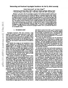
FIG. 1: (Color online.) Schematic representation of the BCS-like dispersion relation of the band insulator with a gap ∆. All states are populated by genuine electrons and holes, resulting in a band insulator, not in a superconductor. Electrons with wave-vectors ≃ ±kF are labeled by R and L respectively. A R electron can have a positive or negative group velocity, as shown on the figure.
II. PRELIMINARIES: HAMILTONIANS, GREEN’S FUNCTIONS, WEAK LOCALIZATION LOOPS
We start with necessary preliminaries on the microscopic description. Insulators (Sec. II A) and charge density waves (Sec. II B) are described by the same formalism. Weak localization-like subgap tunneling is introduced in Sec. II C.
A.
Description of a band insulator
We consider for the band insulator the same dispersion relation as for the BCS model (see Fig. 1), but assume excitation branches supporting either electrons or holes, without condensate and without explicit CDW or superconducting symmetry breaking. The advanced Green’s function connecting two sites α and β separated by a distance Rα,β is given by A gα,β (ω) =
πρN sin (kF |Rα,β |) × (1) kF |Rα,β | −~ω p exp (−|Rα,β |/ξ(ω)), |∆|2 − (~ω)2
where ρN is the normal density of states, kF the Fermi wave-vector corresponding to the p extrema of the dispersion relation, and ξ(ω) = ~vF / |∆|2 − (~ω)2 the coherence length at energy ~ω, with vF the Fermi velocity. In addition, the insulator will be supposed to be quasi1D in the forthcoming Sec. III C. Then, we separate right (label R) from left (label L) branches (underlines are used to avoid confusion with the “A” and “R” labels for advanced and retarded Green’s functions) having a wave-vector ≃ ±kF . An electron on the R branch can have a positive or negative group velocity (see Fig. 1). The corresponding 2×2 matrix Green’s function between
times t and t′ and positions α and β are given by58 A gˆα,β (t, t′ ) = −iθ(t − t′ ) × (2) n o n o h c+ (t′ ), cβ,R (t) i h c+ (t′ ), cβ,L (t) i n α,R o n α,R o . + ′ ′ h c+ α,L (t ), cβ,R (t) i h cα,L (t ), cβ,L (t) i
After Fourier transform, Eq. (2) reduces to −~ω A gˆα,β (ω) = πρN p exp (−|Rα,β |/ξ) (3) |∆|2 − (~ω)2 � � exp (ikF Rα,β ) 0 × 0 exp (−ikF Rα,β ) for propagation at energy ~ω between two points separated by Rα,β along a given chain. Eq. (3) in 1D is compatible with Eq. (1) in 3D because the sin (kF |Rα,β |)/kF |Rα,β | factor in 3D is replaced by cos (kF Rα,β ) in 1D. A coupling to the vector potential due to a magnetic A field is obtained by replacing gˆα,β (ω) in Eq. (2) by A gˆα,β (ω) exp
2π i φ0
Z
β
α
!
A · dr ,
(4)
Rβ where α A · dr is the circulation of the vector potential on a path connecting α to β, and φ0 = h/e is the flux quantum.
B.
Description of a charge density wave 1.
Peierls Hamiltonian
Charge density waves are described on the basis of the electronic part of the Peierls Hamiltonian of spinless
3 ξ A
A
R
A R
R
A
A
R R
A
R R (a) Normal metal chain k
B = f0 (ω) exp (ikF (xα + xβ )) C = f0 (ω) exp (−ikF (xα + xβ )) D = g0 (ω) exp (−ikF (xα − xβ )),
A A
A
R
where the points α and β are at coordinates xα and xβ along the chains, and where ! −~ω 1 p +i (12) g0 (ω) = 4T |∆|2 − (~ω)2
R (b) Gapped system below the gap energy A chain m A A R
A A
R R ξ A
(c) Charge density wave
f0 (ω) =
nanohole A
R
(9) (10) (11)
3.
R
∆ 1 p . 4T |∆|2 − (~ω)2
(13)
Tunneling self-energy
A R (d) Elastic cotunneling in a charge density wave
FIG. 2: (Color online.) Schematic representation in real space of a localization loop inserted in diagrams for the transmission coefficient in a normal metal (a); and in a gapped system below the gap (b). Similar diagrams are obtained from the tunnel terms at the interfaces4 to higher orders. (c) shows a weak localization-like loop for a quasi-1D charge density wave chains pierced by a nanohole (see Sec. IV). (d) shows a process now winding around the hole, and therefore not being modulated by a magnetic flux in the nanohole. The labels “A” and “R” stand for advanced and retarded Green’s functions.
fermions on a 1D chain: X � � + HP = − [T + δ0 cos (2kF x)] c+ x+a0 cx + cx cx+a0 , x
(5) where the average hopping amplitude T has a modulation δ0 (a0 is the lattice parameter). Changing variable from the spatial coordinate x along the chain to the wavevector k, we find X H = − 2T cos (ka0 )c+ (6) k ck k
−
X k
∆c+ k−2kF ck −
X
∆∗ c+ k+2kF ck ,
� 1 � + c+ ca,R + c+ a = √ a,L , 2
(14)
ikF xa + −ikF xa + χ ˆR (xa ) and c+ χ ˆL (xa ) with c+ a,R = e a,L = e (site “a” is at coordinate xa along the chain). The fields χ ˆ+ R(L) (x) are slowly varying as a function of the coordinate x along the chain. The identity
� 1� + + + c + c c + c c ca,L cα,L + c+ α,L α,R α,R a,R a,L a,R 2 (15) leads to the self-energy � � t⊥ 1 1 A ˆ (16) Σα→a = 2 1 1 c+ a cα =
for hopping from α to a, where the entries correspond to different left and right components.
k
with |∆| = δ0 the Peierls gap. 2.
One dimensional chains with an average intra-chain hopping T are supposed to be connected by a weak interchain hopping t⊥ . Interchain hopping corresponds to c+ a cα , encoding the destruction of a spinless fermion at site “α” and its creation at site a in a neighboring chain, as well as to the reversed process. The fermion creation operator c+ a is decomposed in the right (R)- and left (L)+ moving components c+ a,R and ca,L according to
C.
Ballistic Green’s functions
Ballistic propagation within a given CDW chain is described by Eq. (2). The CDW Green’s functions take the form � � A B A , (7) gˆα,β (ω) = C D with A = g0 (ω) exp (ikF (xα − xβ ))
(8)
Weak localization-like loops
A weak localization loop in a normal metal is shown on Fig. 2a. The generalization to subgap transport5 involves a Hikami box59,60 containing an “advanced-advanced” or a “retarded-retarded” transmission mode57 . Fig. 2b shows a weak localization-like diffuson self-crossing in a 3D gapped system (such as a superconductor5,61 ) below the gap energy, and the same type of diagram from higher order terms in the tunnel amplitudes in normal metalinsulator-normal metal (NIN) structures are discussed in the forthcoming Sec. III. The generalization to quasi-1D CDWs (see Sec. IV) corresponds to Fig. 2c, and a process
4
N
N
I
.....
I
N a α
N β b
.....
(b)
(c) a α
..... a α
β b V
β b
N
I
(d)
Conductance
(a)
..... 0
N
h/2e
Φ
I
FIG. 3: (Color online.) Schematic representation of (a) a tight-binding normal metal-insulator-normal metal (NIN) tunnel junction with a hole pierced by a magnetic flux Φ in the insulator (b) the 1D NIN tunnel junction1 , and (c) a geometry with an insulating ring pierced by a flux Φ, and (d) the resulting h/2e oscillations of the conductance with a negative magnetoconductance at low field. The notations a, α, β and b for labeling the interfaces are shown on the figure.
of cotunneling through a CDW is shown on Fig. 2d. As a direct consequence of Eq. (4), the transmission mode associated to Fig. 2b and Fig. 2c is h/2e-periodic as a function of the flux Φ enclosed in the loop (see the discussion in Secs. III and IV). The magnetic field phase factor [see Eq. (4)] accumulated by the “advanced” and “retarded” Green’s functions cancel with each other in the diagram on Fig. 2d, which is thus not modulated by a magnetic field. III.
TUNNELING THROUGH A BAND INSULATOR
We start with a tunnel junction consisting of a band insulator inserted in between two normal electrodes. The assumption on the dispersion relation (see Fig. 1 and Sec. II A) is representative of extrema of the dispersion relation at wave-vectors pn , with 2π/pn much smaller than the thickness of the insulating layer traversed by tunneling electrons. A.
model1 ). Eq. (17) is valid to all orders in the tunnel amplitudes ta and tb , from tunnel junctions to highly transparent interfaces. The fully dressed advanced and R retarded Green’s functions GA α,β (ω) and Gβ,α (ω) describe propagation from α to β and from β to α respectively while including all possible excursions in the normal elecA R trodes, as opposed to the notations gα,β (ω) and gβ,α (ω) restricted to electrodes isolated from each other, with ta = tb = 0. Physically, electron propagation across the insulator from electrode Na at time τa to electrode Nb at time τb [corresponding to the advanced Green’s function GA α,β (ω)] occurs within the same process as propagation of an electron backward in time from electrode Nb at time τb to electrode Na at time τa [corresponding to the retarded Green’s function GR β,α (ω)]. As we show, both electrons propagating forward and backward in time can bounce independently at the interfaces during a tunneling process, corresponding to contributions to the conductance of higher order in tunnel amplitudes. This amounts to evaluating a transition probability as the square of a transition amplitude, which contains interference terms corresponding among others to weak localization-like subgap tunneling.
Ring geometry within microscopic Green’s function 2. 1.
Expansion of the transport formula
Transport formula
We start with the Caroli, Combescot, Nozi`eres and Saint-James1 expression of the conductance G(ω) of a 1D Na INb junction:
Considering a geometry in which a quasi-1D ring made of a band insulator is connected to two normal electrodes (see Fig. 3c), the fully dressed advanced Green’s function GA α,β [see Eqs. (8) and (9) in Ref. 1]
G(ω) = (17) 2 e R 4π 2 ρa,a (ω)ta,α GA α,β (ω)tβ,b ρb,b (ω)tb,β Gβ,α (ω)tα,a , h where ~ω is equal to the bias voltage energy eV ; ρa,a (ω) and ρb,b (ω) denote the density of states in electrodes “a” and “b” at energy ~ω; ta ≡ ta,α = tα,a and tb ≡ tb,β = tβ,b are the hopping amplitudes for the contact with the points α and β at the extremities of the insulator to their counterparts a and b in the normal electrodes (see Figs. 3a for planar interfaces, and Fig. 3b for the 1D
GA α,β =
A gα,β A ′ A ′ A dA a db − (da ) (db )
,
(18)
A A with dA = 1 − gα,α tα,a ga,a ta,α and dA = 1 − a b A A ′ A A A gβ,β tβ,b gb,b tb,β , (da ) = gβ,α tα,a ga,a ta,α , (d′b )A = A A gα,β tβ,b gb,b tb,β , is expanded in multiple crossings of the ring:
GA α,β =
A gα,β A dA a db
(19)
5 y1 β y1 =l1
Normal metal x α’ y2 =0
Insulator α y1 =0
Fluxφ x=0
x’=0
β ’ x’ y2 =l2
Normal metal
Insulator
y2
FIG. 4: (Color online.) Notations used in Sec. III B for describing an insulating ring connected to two normal electrodes.
+
A 2 A (gα,β ) gβ,α A 2 (dA a db )
A tβ,b gb,b tb,β
�
� A tα,a ga,a ta,α + ...
The expansion in Eq. (19) is justified by the damping of the electron wave-functions in the insulator4,44 : the second term with three crossings of the insulator in Eq. (19) is small compared to the first term involving a single crossing if we suppose that half of the perimeter of the ring is large compared to the coherence length. Separating propagation from α to β along the upper and lower branches of the ring and including the phase factors related to the enclosed flux Φ, the combination of Eq. (17)-(19) to Eqs. (A2)-(A5) leads to dominant h/2e oscillations of the conductance with the magnetic flux Φ, and to a negative magnetoresistance at low field (see Fig. 3d). More precisely, the magnetic field is introduced by substituting Eq. (4) into Eq. (19) and keeping the lowest R order oscillating term in the combination GA α,β Gβ,α (ω) entering the expression of the conductance G(ω) given by Eq. (17). Such term contains three advanced and one retarded Green’s functions, each contributing to a factor exp (iπΦ/2φ0 ). As a result of averaging over the
Fermi phase factors (see Appendix A), the lowest order oscillating part of the conductance is proportional to cos (4πΦ/φ0 ) = Re[exp (4iπΦ/φ0 )], with h/2e-periodic oscillations of the conductance with the flux Φ, typical of a weak localization-like phenomenon. The sign of the cos (4πΦ/φ0 ) oscillations in the conductance corresponds to a negative magnetoconductance at low field, and it is thus inverted as compared to standard weak localization in a normal metal (see Fig. 5 in the forthcoming Sec. III B). Similar features were obtained by Latyshev et al.6 in experiments on CDWs (see the items 3. and 4. in the summary of experiments in the Introduction). The coincidence is explained in Sec. IV by the same underlying weak localization-like subgap tunneling processes for band insulators and CDWs. B.
Wave function approach
We discuss now magneto-oscillations of the tunneling current via wave function matching62,63 . The goal is to confirm qualitatively the Green’s function approach in Sec. III A, and to present concrete results for the magnetic oscillations. Let us consider the geometry on Fig. 4 in which a ring (made of an insulator in which wave functions are damped over a length ξ and oscillate with wave-vector kF ) is connected to two normal electrodes (with propagation of plane waves). The band insulator is supposed to have the same BCS dispersion relation as described above (see Sec. II A). The corresponding wave-vectors ±kF ± i/ξ lead to oscillations of the wavefunction with period λF = 2π/kF and to a damping over the insulator coherence length ξ. Following Refs. 62,63, the wave-functions ψL (x) in the left normal electrodes, ψ1 (y1 ) in the upper branch of the ring (of length l1 ), ψ2 (y2 ) in the lower branch (of length l2 ) and ψR (x′ ) in the right normal metal are given by
ψL (x) = exp(−ikF x) + b exp(ikF x) � � � � ψα y1 − l1 2π ψ1 (y1 ) = exp −i y1 A0 sin (kF (l1 − y1 )) exp sin (kF l1 ) φ0 ξ � � � � y1 2π ψβ exp i (l1 − y1 )A0 sin (kF y1 ) exp − + sin (kF l1 ) φ0 ξ � � � � ψα′ y2 − l2 2π ψ2 (y2 ) = exp −i y2 A0 sin (kF (l2 − y2 )) exp sin (kF l2 ) φ0 ξ � � � � −y2 2π ψβ ′ exp i (l2 − y2 )A0 sin (kF y2 ) sin + sin (kF l2 ) φ0 ξ ψR (x′ ) = b′ exp(ikF x′ ),
where we choose a radial gauge with a component A0 of the potential vector, and where the coefficients b′ and b
(20)
(21)
correspond to the transmission and backscattering ampli-
6 tudes, and ψα , ψβ , ψα′ and ψβ ′ denote the amplitudes of the components of the insulating wave-function localized on the different nodes. Wave-function matching takes the form ψL (0) = ψ1 (l1 ) = ψ2 (0), ψR (0) = ψ1 (0) = ψ2 (l2 ), and matching of the derivative of the wave-function at the left and right nodes is given by
2
(22)
(24)
is then evaluated by averaging over the Fermi phase factors kF l1 and kF l2 , and it is shown on Fig. 5 for different values of R/ξ. The matching equations (20-23) reduce to those of a normal metal62,63 for R/ξ ≪ 1 and a positive magnetoconductance with φ0 /2 periodicity is then recovered in this range of R/ξ (as for standard weak localization in a normal metal where increasing a magnetic field suppresses localization). As seen from Fig. 5, the magnetoconductance is almost φ0 /4-periodic at the cross-over R ∼ ξ and becomes again φ0 /2-periodic for R/ξ ≫ 1, with a shape of oscillations characteristic of the evanescent wave-function weak localization-like oscillations discussed above in Sec. III A within microscopic Green’s functions. We obtain h/2e-periodicity for R/ξ ≫ 1, but not exactly of the form cos (4πφ/φ0 ) obtained above in Sec. III A 2 within microscopic Green’s functions. This is because of a remaining positive magnetoconductance within a small low field region around φ = nφ0 /2 (with n and integer), in agreement with Ref. 64. Higher order harmonics play also a role because of the highly transparent contacts used for the ring geometry on Fig. 4 [see Eqs. (22) and (23)].
C.
7.5
5
2.5
(23)
0
as deduced from integrating the Schr¨odinger equation with respect to coordinates over a small area including a node. The transmission coefficient T0 (Φ) = |b′ (Φ)|2
R/ξ=0.5 R/ξ=1 R/ξ=2.5
3
∂ψ2 ∂ψ1 (l1 ) − (0) = 0 ∂y1 ∂y2 ∂ψ2 ∂ψ1 (0) + (l2 ) = 0, ∂y1 ∂y2
10 |b’(φ/φ0)|
∂ψL (0) + ∂x ∂ψR − (0) − ∂x
−
10
0
0.5
1 φ/φ0
1.5
2
FIG. 5: (Color online.) Transmission coefficient of the ring made of a band insulator with the dispersion relation on Fig. 1 as a function of the flux Φ enclosed in the loop, normalized to the flux quantum φ0 = h/e. Different curves correspond to the different values of R/ξ shown on the figure. The value of λF = 2π/kF is small compared to ξ.
the conductance, and involve a transfer of 2kF momentum from one interface to the other across the insulating electrode. In a quasi-1D geometry, electrons above the gap on the right branch (label R) of the BCS-like dispersion relation can propagate physically to the left or to the right according to their group velocity (see Fig. 1). This means that a recoil of the insulator is a necessary condition for weak localization-like subgap tunneling with quasi-1D insulators in the geometry of Fig. 6. Moreover, transfers of 2kF momentum are the hall-mark of CDW Andreev processes12,13,14 , which suggests a connection between the special type of tunnel junctions considered here and the CDW case (see Sec. IV). Finally, disorder in the normal electrode tends to localize the electron wave functions in the vicinity of the interfaces. The processes on Fig. 6 are thus facilitated by diffusive motion in the normal electrodes.
Coupling to a momentum channel
Now, we note that propagation across the insulator defines a “tunnel” of cross section area ξ02 , with ξ0 ∼ a0 ǫF /∆ the coherence length (a0 is the lattice spacing and ǫF the Fermi energy). Such a narrow channel is compatible with the following additional assumption: the insulator (with the dispersion relation on Fig. 1) consists of linear 1D chains perpendicular to the interfaces. Electrons on the right and left branches (denoted by R and L) are taken into account according to Sec. II A. We deduce that the specific set of R and L labels on Fig. 6a does not contribute to the conductance once the summation over the Fermi oscillations in different channels is carried out. By contrast, branch crossing at the interfaces (see the R and L labels on Fig. 6b) contribute for a finite value to
IV.
SUBGAP TUNNELING BY A QUANTUM INTERFERENCE EFFECT AROUND A NANOHOLE IN A CHARGE DENSITY WAVE
Now, we present our main result and show that weak localization-like subgap tunneling discussed above for tunnel junctions (Sec. III) leads to a quantum interference effect also in charge density waves, therefore explaining the experiment by Latyshev et al.6 on oscillations of the CDW current around a nanohole. Before discussing weak localization-like subgap tunneling in Sec. IV B, we provide in Sec. IV A a mechanism of transport around a nanohole in a CDW. The disordered case is discussed in Appendix B.
7 α
N R R L L
R
L
A
L L
R R
(a)
β
I A A
L L
R R
A R L A L L L L
N
L
∆ p=−2kF
R R
α
R A I
R R β
L R L L L L
N
FIG. 6: (Color online.) Weak localization-like loops in a normal metal-insulator-normal metal junction with two sets of right-left labels. The right-left branches and therefore the momentum of the tunneling electrons is conserved in (a). The conductance is vanishingly small for (a) because of the absence of propagation from α to β of the advanced-advanced A A transmission mode [gα,β,R,R gα,β,R,R ≃ 0 – see Eq. (3)]. (b) shows a process leading to a finite tunneling current A A [gα,β,R,R gα,β,L,L is limited by the insulator coherence length – see Eq. (3)]. Transfers of momentum by ∆p = ±2kF propagate across the insulator according to the arrows, in parallel to evanescent wave charge tunneling.
A.
Coupling between the sliding motion and weak localization-like subgap tunneling 1.
Notations
The mechanism discussed now for CDW transport, based on weak localization-like subgap tunneling around a nanohole, is first discussed for a few interrupted chains coupled by a transverse hopping t⊥ . The more realistic case of a normal island around the nanohole will be discussed afterwards. From the point of view of notations, the interrupted chains are labeled by k = 2, ..., N − 1, and are connected by transverse hopping terms to the two uninterrupted chains k = 1 on top and k = N on bottom (see Fig. 7 for N = 3 and Fig. 2c for N = 5). (k) Chains k = 2, ..., N − 1 are interrupted at positions x0 (k) at the left of the nanohole, and at x1 at the right of the (2) (2) nanohole (see x0 and x1 on Figs. 7b and 8 for a single interrupted chain).
2.
follows ∂ϕk (x, τ )/∂τ = ω0 , with ω0 the sliding frequency, corresponding to the relation (see for instance Ref. 33) j (k) (x, τ ) =
R R
∆ p=2k F
(b)
N
Deceleration and acceleration of the sliding motion in interrupted chains
Assuming an overall sliding motion, the phase ϕk (x, τ ) at position x along chains k = 1 and k = N and time τ
e ∂ϕk (x, τ ) π ∂τ
(25)
between the CDW current and the time derivative of the CDW phase variable in chain k. The boundary condi(k) tion on the hole leads to ∂ϕk (x, τ )/∂τ = 0 at x = xi (i = 0, 1 and k = 2, ..., N − 1) (no collective current (k) (k) is flowing across x0 and x1 in the direction parallel (k) to the chains), and to ∂ϕk (x, τ )/∂τ = ω0 for x ≪ x0 (k) and x ≫ x1 (the collective sliding motion is recovered far away from the nanohole). The resulting profile of ∂ϕk (x, τ )/∂τ (see Fig. 7c for N = 3) corresponds to the conversion of the CDW current into a normal current65,66,67,68 ∂ρk (x, τ )/∂τ , emitted according to the arrows on Fig. 7b, from the intermediate chain labeled by k: (k)
(k)
∂ρk (x0 , τ ) e ∂ 2 ϕk (x0 , τ ) =− , ∂τ π ∂x∂τ
(26)
as deduced from the continuity equation. 3.
Charge accumulation
Quasiparticles emitted from the slowing down of the sliding motion at the left of the nanohole are reabsorbed at its right where the sliding motion accelerates, leading to charge accumulation at the extremities of the interrupted chains at the left of the hole, described by the chemical potential δµ & ∆. The current Ik (Φ) emitted from chain k is given by Z e X δµ Tk→m (Φ, t⊥ , ~ω)d(~ω), (27) Ik (Φ) = h m 0 where Tk→m (Φ, t⊥ , ~ω) is the total dimensionless transmission coefficient at energy ~ω transfering electrons from chain k at the left of the nanohole to chain m at its right (see chains k and m on Fig. 2). The transmission coefficient Tk→m in Eq. (27) is a multichannel generalization of T0 in Eq. (24). Similarly to the case of band insulators (see Sec. III), the subgap tunneling current for the processes on Fig. 8 is h/2e-periodic as a function of the enclosed flux Φ [see Eq. (28) below obtained from Eq. (4)]. The oscillations appear only in the presence of the sliding motion (item 2. in the Introduction). The smallness of interchain couplings in the transmission coefficient can be balanced by the integral over energy in Eq. (27), up to the large value of the Peierls gap in the compound NbSe3 used by Latyshev et al.6 . The non modulated part of the current for a single interrupted chain is proportional to I0 ∼ (e/h)(t⊥ /T )4 (δµ− ∆) while the modulated part Imod = (e/h)(t⊥ /T )8 ∆ is independent on δµ−∆. The ratio Imod /I0 = (t⊥ /T )4 ∆/(δµ−∆) is thus a function of the values of t⊥ /T and of (δµ−∆)/∆.
8
nanohole chain (3) current flow
B
y
z y 0
ω0
chain (2)
chain (2) x
0
x
chains (1) and (3)
dϕn(x,τ)/d τ
(a)
chain (1)
0
x0(2)
x1(2)
x
(c)
(b)
FIG. 7: (Color online.) Schematic representation of (a) a film of NbSe3 pierced by nanoholes with a magnetic field B along the z axis. The current is supposed to flow on average along the x axis parallel to the chains. (b) shows a nanohole interrupting a single CDW chain along the x axis. The arrows on (b) represent schematically the emission and absorption of normal carriers due to the slowing down and acceleration of the sliding motion at the left and right of the nanohole respectively. The profile of ∂ϕn (x, τ )/∂τ along chains n = 1, 2, 3 is shown schematically on (c).
ξ
x(2) y(2) 0 0
chain (3)
A A
A
chain (2)
R
A R
A
chain (1)
x1(2) y1(2)
R
x
FIG. 8: (Color online.) The same weak localization-like tunneling process as on Fig. 2c for a nanohole in a CDW, as on Fig. 7.
Normal region around the nanohole
Nanohole A R
A
A R
A R
R R A R A A
Advanced−retarded transmission mode Advanced−advanced transmission mode
FIG. 9: (Color online.) Schematic representation of a weak localization-like tunneling events involving an “advancedadvanced” transmission mode, and an “advanced-retarded” transmission mode in the presence of a normal region around the nanohole, at energies smaller than the island level spacing.
However, it was already noticed15 that the damaged region of the CDW around a nanohole is likely to be normal, in which case the relative amplitude of the modulation may be large, as suggested by Fig. 5 for a single channel. The corresponding tunneling process is shown on Fig. 9 at energy smaller than the normal region level spacing δ. Propagation across the normal region supports “advanced-advanced” transmission modes because the level spacing δ plays the role of a gap. The value of δ is comparable to the Peierls gap, as it can be seen from the estimate ~vF /D, with D the diameter of the nanohole, leading to the rough estimate δ/kB ∼ 100 K, with vF ≃ 105 ms−1 as an order of magnitude of the Fermi velocity. As expected, the level spacing of an object of size D ∼ ξ is comparable to the Peierls gap ∆. B.
Weak localization-like subgap tunneling transmission coefficient
We evaluate now the weak localization-like subgap tunneling transmission coefficient given by the diagram on Fig. 8, in the absence of normal region around the nanohole as on Fig. 9. It takes the form � � � �8 2Φ t⊥ F (~ω) Ξ(~ω) cos , (28) T (Φ, t⊥ , ~ω) = T φ0 The factor Ξ(~ω) encodes the damping of subgap transmission: ! ! (2) (2) (2) (2) x1 − x0 y1 − y0 exp − , Ξ(~ω) = exp − ξ(ω) ξ(ω) (29) and F (~ω) takes the form h 4� F (~ω) = Re 4 |g0 (ω)| (g0 (ω))2 + (f0 (ω))2 (30) �o n × |g0 (ω)|2 + |f0 (ω)|2 ,
9 with g0 (ω) and f0 (ω) given by Eqs. (12) and (13). The 2 2 term |g0 (ω)| + |f0 (ω)| corresponds to the “advancedretarded” transmission mode in the lower branch (see Fig. 7d) and the term (g0 (ω))2 + (f0 (ω))2 accounts for the “advanced-advanced” transmission mode in the upper branch. The later involves transmission of momentum in parallel to evanescent wave tunneling, similarly to the tunnel junction discussed in Sec. III (see Fig. 6b). The coherence p length ξ(ω) at energy ~ω is given by ξ(ω) = ~vF / |∆|2 − (~ω)2 , with vF the Fermi velocity. The sliding motion induces a time dephasing of weak localization-like tunneling because the CDW phase evolves in time in the course of weak localization winding. Such couplings are however not probed in experiments such as in Ref. 6 because the sliding motion is slow compared to the time scale ~/∆, with ∆ the Peierls gap. A ballistic evaluation of the transmission coefficient in the CDW chains is justified by the fact that tunneling quasiparticles travel over extremely short distances corresponding to the diameter of the hole, comparable to the CDW coherence length of order 10 nm in experiments6 . Similar results were obtained in a different limit by treating disorder in the ladder approximation along Ref. 61 (the principle of the calculation is detailed in Appendix B).
CDW ground state. The collective momentum channel may be realized by a recoil in the specific case of a quasi1D insulator. The analogy between CDWs and quasi-1D insulators and on the other hand the expected normal island in the Latyshev et al. experiment6 shows that propagation through the CDW condensate is not a necessary condition for the modulations of the resistance as a function of a magnetic field.
Acknowledgments
R.M. thanks Yu. Latyshev, P. Monceau and A.A. Sinchenko for stimulating discussions on their experiments, S. Brazovski for a crucial discussion at the early stages of this work, and acknowledges a fruitful discussion with D. Carpentier and E. Orignac, as well as with J. Dumas and with B. Dou¸cot. S. D. and R. M. thank D. Feinberg, S. Florens, M. Houzet and R. Whitney for having provided useful insights and suggestions. Ref. 57 was provided to us by M.V. Feigelman.
APPENDIX A: TUNNELING THROUGH AN INSULATOR WITH PLANAR INTERFACES 1.
V.
CONCLUSIONS
To conclude, we discussed for CDWs a mechanism of tunneling via quantum interference effect initially proposed for superconducting hybrids4,5,57 . The considered tunneling mechanism combined to charge accumulation due to the deceleration of the CDW at the approach of the nanohole leads to the same features as in the experiment by Latyshev et al.6 on h/2e oscillations of the CDW current around a nanohole (see the Introduction): 1. Weak localization-like loops due to higher order terms in the tunnel amplitudes are present even without nanoholes. They induce no oscillations in the magnetoresistance in the absence of nanohole because of the absence of charge accumulation in this case; 2. No charge accumulation is present with nanoholes but without sliding motion; 3. h/2e-periodic oscillations of the resistance as a function of the magnetic flux are obtained with nanoholes and with sliding motion because the diameter of the nanohole is comparable to the coherence length, so that weak localization-like loops enclose approximately the same area as the nanohole; 4. The positive magnetoresistance at low field is already obtained for the normal tunnel junction; 5. The only energy/temperature scale in weak localization-like subgap tunneling is the gap or the level spacing of the metallic island, comparable in magnitude to the Peierls gap. An underlying issue is whether the experiment by Latyshev et al.6 provides evidence for an interference effect associated to the collective quantum mechanical
Multichannel transport formula
The exact generalization of the 1D transport formula (see Eq. (17)) to a multichannel Na INb tunnel junction with extended interfaces (see Fig. 3a) is given by G(ω) =
X
i,j,k,l
4π 2
e2 ρa ,a (ω)taj ,αj GA αj ,βk (ω)tβk ,bk h i j
× ρbk ,bl (ω)tbl ,βl GR βl ,αi (ω)tαi ,ai ,
(A1)
where an underlying tight-binding lattice is assumed. The density of states ρai ,aj connects the two sites ai and aj at the same interface. The summations over (i, j) and (k, l) run over all sites at the Na I and INb interfaces respectively. The transport formula given by Eq. (A1) is represented on Fig. 10a, where the bold red and dashed R blue lines correspond to GA α,β and Gβ,α respectively. The densities of states in the normal electrodes are represented by the connection of a wavy line on the figure.
2.
Perturbative expansion
Higher order tunnel processes containing weak localization-like contributions are obtained by expanding systematically Eq. (A1) in the tunnel amplitudes according to the Dyson equations. Fig. 10 b-f shows combinaR tions of some terms in GA α,β to some terms in Gβ,α The weak localization-like diagrams on Fig. 10d and e are made of three “advanced” and one “retarded” Green’s functions, and look similar to the diagram on Fig. 2b
10
N
j
N
I
k
N
I
N
N
I
N
A
A
A A
R i
N
(a) I
R
(b)
l
N
N
A
N R
A
A
(c)
I
A A R
A R
I
N
R
A
R R
A
(e)
A
A
R R
R
R
(d)
N
(f)
FIG. 10: (Color online.) Top view of Fig. 3a showing the first terms in perturbation theory in the tunnel amplitude for a normal metal-insulator-normal metal (NIN) tunnel junction. The exact transport formula is shown schematically on (a), where the thick solid (dashed) lines correspond to the fully dressed advanced (retarded) Green’s functions. The wavy lines indicate the insertion of the density of states in the normal electrodes (see Fig. 3b). The other panels correspond to a few of the first low order terms in the perturbative expansion in the tunnel amplitudes. As for usual weak localization in a normal metal (see Fig. 2a), the weak localization-like tunneling processes on (d) and (e) lead to dominant h/2e oscillations as a function of the magnetic flux once the summation over all channels has been carried out.
A
corresponding to a disorder self-energy in the bulk of a superconductor.
A
+ R
A
+
A
R
R A
+ 3.
Averaging over the conduction channels
R
R
+ ... The diagrams appearing in perturbation theory are averaged over the different “channels” in real space, corresponding to a summation over the discrete tight-binding sites at which diagrams cross the interfaces. The result of the channel averaging procedure depends on assumptions about the insulator band structure. Averaging over the conduction channels amounts to evaluating the integrals g A (Rα,β , ω)g R (Rα,β , ω) (A2) Z Rα,β +2π/kF kF g A (r, ω)g R (r, ω)dr (A3) = 2π Rα,β � � �2 � πρN 2Rα,β (~ω)2 1 (A4) exp − = 2 kF Rα,β |∆|2 − (~ω)2 ξ(ω) = g A (Rα,β , ω)g A (Rα,β , ω),
(A5)
where g A (Rα,β , ω) is given by Eq. (1), and where the last equality is valid for ~ω < ∆ below the gap. To summarize, Aharonov-Bohm like oscillations are washed out by channel averaging with the band structure on Fig. 1 and h/2e-periodic weak localization-like diagrams on Figs. 10d and e contribute to leading order (in the tunnel amplitudes) to the oscillations of the conductance as a function of the magnetic flux. The same conclusion holds for the ring geometry in Sec. III A 2.
FIG. 11: (Color online.) The ladder series for the transmission coefficient. The vertical blue lines correspond to impurities in the ladder approximation. The green boxes corresponding to Eq. (B5) indicate the recursive elimination of the impurities from one extremity of the ladder61 .
APPENDIX B: EVALUATION OF THE TRANSMISSION COEFFICIENT OF A DISORDERED CDW 1.
Green’s function of a disordered CDW
The Green’s function7,69 of a disordered CDW is evaluated in the Born approximation as in the superconducting case, where we introduce forward- and backwardscattering potentials u and v. With the notation in Ref. 61 in the superconducting case, we find τ1 ˆ ω) = ~ω + ξ τˆ3 + ∆ˆ G(ξ, , 2 2 2 (~ω) − ξ − ∆
(B1)
with τˆ1 and τˆ3 the Pauli matrices given below, with ω = ω(1 + α), ξ = ξ + β and ∆ = ∆(1 + γ), with α =
1 1 √ + √ 2 2 τf ∆ − ω τb ∆2 − ω 2
(B2)
11 �Z � 1 dk 2 2 = − |u| + |v| λF 2 2π (~ω) − ∆2 − ξ 2 � �Z ξ dk 2 2 (B3) β = |u| + |v| λF 2π (~ω)2 − ∆2 − ξ 2 1 p γ = (B4) τf ∆2 − (~ω)2 Z 1 dk 2 , = |u| λF 2π (~ω)2 − ∆2 − ξ 2
ˆ = Fˆ 2 leads to the Acting twice with Fˆ according to G closed 2 × 2 equations �� � � � � τˆ0 τˆ0 a b ˆ (B15) G = τˆ1 b ′ a′ τˆ1 �� � � � � iˆ τ2 τ2 c d ˆ iˆ , (B16) G = τˆ3 τˆ3 d′ c′ with a = (A2 − B 2 )(1 − α)2 (~ω)2 −9A(A + B)(1 + γ)2 ∆2 b = A(10A − B)(1 − α)(1 + γ)~ω∆ b′ = −(A + B)(10A − B)(1 − α)(1 + γ) ×~ω∆ a′ = 9A2 (1 − α)2 (~ω)2 −A(A − B)(1 + γ)2 ∆2 ,
where λF is the Fermi wave-vector, ~ω the energy, ∆ the CDW gap and ξ the kinetic energy with respect to the Fermi level. The notations τf and τb stand for the forward and backward scattering times respectively. We keep in the following calculations a finite shift β of the chemical potential that does however not enter the properties that we consider. 2.
Evaluation of ladder diagrams for the transmission coefficient
where u, v and w are Gaussian distributed random variable. The Pauli matrices τˆn are such that � � � � 0 1 1 0 (B6) , τˆ1 = τˆ0 = 1 0 0 1 � � � � 1 0 0 1 . (B7) , τˆ3 = iˆ τ2 = 0 −1 −1 0
d′ = 3A(2A + B)(1 − α)(1 + γ)~ω∆.
+∞ X
n=1 +∞ X
(B8)
n=1
(B10) (B11)
.
�
τˆ0 0
�
ˆn G
�
0 τˆ1
�
= A1
�
τˆ0 0
�
= A2
�
τˆ0 0
�
+ B1
�
0 τˆ1
�
(B25)
+ B2
�
0 τˆ1
�
(B26)
m2 (8kF2 + 19q 2 )|u|2 (B12) 5 4 4~ kF (∆2 (1 + γ)2 − ~ω 2 (1 − α)2 )1/2 (8kF2 + 19q 2 )|v|2 m2 (B13) 5 4 4~ kF (∆2 (1 + γ)2 − ~ω 2 (1 − α)2 )1/2 (B14)
λ+ λ− (1) (1) ψ +Y ψ 1 − λ+ + 1 − λ− − λ− λ+ (2) (2) ψ +Y ψ = X 1 − λ+ + 1 − λ− − λ− λ+ (1) (1) ψ+ + X ′ ψ = −X ′ 1 − λ+ 1 − λ− − λ+ λ− (2) (2) = −X ′ ψ+ + X ′ ψ , 1 − λ+ 1 − λ− −
A1 = X
(B27)
B1
(B28)
A2 B2
with
B =
ˆn G
We find (B9)
−A(1 + γ)∆ˆ τ1 ,
A =
(B24)
The final step is to decompose the initial condition on the ˆ and evaluate the coefficients in matrix eigenvectors of G geometric series such as
We find
Fˆ (iˆ τ2 ) = 3(A + B)(1 + γ)∆ˆ τ0 −3A(1 − α)~ωˆ τ1 Fˆ (ˆ τ3 ) = (−A − B)(1 − α)~ωˆ τ0
(B20)
c = −3(A − B)(2A + B)(1 − α)(1 + γ) (B21) ×~ω∆ � d = −9A (A + B)(1 + γ)2 ∆2 (B22) � 2 2 −A(1 − α) (~ω) � ′ c = (A − B) (A + B)(1 − α)2 (~ω)2 (B23) � 2 2 − A(1 + γ) ∆
Fˆ (ˆ τn ) = (B5) � � �† � Z dk u w ˆ R (k + q, ω) u w , ˆ A (k, ω)ˆ G τn G v u 2π v u
−3A(1 − α)~ωiˆ τ2
(B18) (B19)
and expressions of the same type for c, d, c′ , d′ :
To include disorder70 , the transmission coefficients in the ladder approximation (see Fig. 11) are evaluated according to Smith and Ambegaokar61 by iterations of
Fˆ (ˆ τ0 ) = (−A + B)(1 − α)~ωˆ τ3 −3A(1 + γ)∆iˆ τ2 ˆ F (ˆ τ1 ) = (A − B)(1 + γ)∆ˆ τ3
(B17)
(B29) (B30)
with � � b′ − a 1 1− ′ X = 2 (b − a)2 + 4a′ b � � 1 b′ − a Y = 1+ ′ 2 (b − a)2 + 4a′ b
(B31) (B32)
12 b − a)2 + 4a′ b � � p 1 a + b′ ± (a − b′ )2 + 4a′ b = 2 p b′ − b ± (a − b′ )2 + 4a′ b = 2b
X′ = λ± (2)
ψ±
(b′
(B33) (B34)
in both sectors leads to an expression of all right-left components of the transmission coefficient of a disordered CDW. The later can be used to evaluate the weak localization-like subgap tunneling diagrams.
(B35)
(1)
and ψ± = 1. Carrying out the same calculation in the sector (iˆ τ2 , τˆ3 ) and evaluating geometric series like +∞ X
n=1
1
2
3
4 5
6
7
8
9
10
11
12
13
14
15
16
17
18 19
ˆ n Fˆ G
�
τˆ0 0
�
(B36)
C. Caroli, R. Combescot, P. Nozi`eres and D. Saint-James, J. Phys. C: Solid St. Phys. 4, 916 (1971); ibid. 5, 21 (1972). D.S. Golubev and A. Zaikin, Phys. Rev. B 74, 245329 (2006). Ya. M. Blanter, V.M. Vinokur, and L.I. Glazman, Phys. Rev. B 73, 165322 (2006). R. M´elin, Phys. Rev. B 73, 174512 (2006). S. Duhot and R. M´elin, Eur. Phys. J. B 53, 257 (2006); Phys. Rev. B 75, 184531 (2007). Yu. I. Latyshev, O. Laborde, P. Monceau and S. Klaum¨ unzer, Phys. Rev. Lett. 78, 919 (1997). Charge Density Waves in Solids, edited by L.P. Gor’kov and G. Gr¨ uner, Modern Problems in Condensed Matter Science Vol. 25 (North Holland, Amsterdam, 1989). K.O’Neill, E. Slot, R. Thorne and H. van der Zant, J. Phys. IV France 131, 221 (2005). E. Slot, M.A. Holst, H.S.J. van der Zant, and S.V. ZaitsevZotov, Phys. Rev. Lett. 93, 176602 (2004). Yu. I. Latyshev, B. Pannetier and P. Monceau, Eur. Phys. J. B 3, 421 (1998). Z.Z. Wang, J.C. Girard, C. Pasquier, D. J´erome, and K. Bechgaard, Phys. Rev. B 67, 121401 (2003). A.A. Sinchenko, Yu. I. Latyshev, S. G. Zybtsev, I. G. Gorlova, P. Monceau, Pis’ma Zh. Eksp. Teor. Fiz. 64, 259 (1996) [JETP Lett. 64, 285 (1996)]; A.A. Sinchenko, Yu. I. Latyshev, S. G. Zybtsev, I. G. Gorlova, Zh. Eksp. Teor. Fiz. 113, 1830 (1998) [JETP 86, 1001 (1998)]; Yu.I. Latyshev and A.A. Sinchenko, Pis’ma Zh. Eksp. Teor. Fiz. 75, 714 (2002) [JETP Letters 75, 593 (2002)]. A.L. Kasatkin and E.A. Pashitskii, Fiz. Nizk. Temp. 10, 640 (1984); A.L. Kasatkin and E.A. Pashitskii, Fiz. Tverd. Tela (Leningrad) 27, 2417 (1985) [Sov. Phys. Solid State 27, 1448 (1985)]. S.N. Artemenko and S.V. Remizov, Pis’ma Zh. Eksp. Teor; Fiz. 65, 50 (1997) [JETP Lett. 65, 53 (1997)]. M.I. Visscher, B. Rejaei and G.E.W. Bauer, Phys. Rev. B 62, 6873 (2000). E.N. Bogachek, I.V. Krive, I.O. Kulik, and A.S. Rozhavsky, Phys. Rev. B 42, 7614 (1990). J.H. Miller, Jr., C. Ord´ on ˜ ez and E. Prodan, Phys. Rev. Lett. 84, 1555 (2000). G. Montambaux, Eur. Phys. J. B 1, 377 (1998). J. Yi, M.Y. Choi, K. Park, E.-H. Lee, Phys. Rev. Lett. 78, 3523 (1997)]; N. Nathanson, O. Entin-Wohlman and B. M¨ uhlschlegel, Phys. Rev. Lett. 80, 3416 (1998);G. Montambaux, Phys. Rev. Lett. 80, 3417 (1998).
20
21 22 23
24
25
26
27
28
29
30
31
32 33
34
35
36
37
38
39
40 41
42
L.P. Gorkov, Pis’ma Zh. Eksp. Teor. Fiz. 38, 76 (1983) [JETP Lett. 38, 87 (1983)]. S.N. Artemenko and A.F. Volkov, in Ref. 7, Chap. 9. S.A. Brazovskii, in Ref. 7, p. 425. S.A. Brazovskii and S.I. Matveenko, Zh. Eksp. Teor. Fiz 99, 1539 (1991) [Sov. Phys. JETP 72, 860 (1991)]. S. Ramakrishna, M.P. Maher, V. Ambegaokar and U. Eckern, Phys. Rev. Lett. 68, 2066 (1992). M.P. Maher, T.L. Adelman, S. Ramakrishna, J.P. McCarten, D.A. DiCarlo and R.E. Thorne, Phys. Rev. Lett. 68n 3084 (1992). T.L. Adelman, M.C. de Lind van Wijngaarden, S.V. Zaitsev-Zotov, D. DiCarlo and R.E. Thorne, Phys. Rev. B 53, 1833 (1996). H. Requardt, F. Ya. Nad, P. Monceau, R. Currat, J.E. Lorenzo, S. Brazovskii, N. Kirova, G. Gr¨ ubel and Ch. Vettier, Phys. Rev. Lett. 80, 5631 (1998). N. Hatakenaka, M. Shiobara, K. Matsuda and S. Tanda, Phys. Rev. B 57, R2003 (1998). Y. Takane, J. Phys. Soc. Jpn. 71, 1019 (2002), 71, 1824 (2002); Y. Takane and K. Wakabayashi, J. Phys. Soc. Jpn. 70, 1869 (2001). N.P. Ong, G. Verma and K. Maki, Phys. Rev. Lett. 52, 663 (1984). S. Brazovskii, N. Kirova, H. Requardt, F. Ya. Nad, P. Monceau, R. Currat, J.E. Lorenzo, G. Gr¨ ubel and Ch. Vettier, Phys. Rev. B 61, 10640 (2000). S.N. Artemenko, Phys. Rev. B 67, 125420 (2003). S. Brazovskii and T. Nattermann, Advances in Physics 53, 177 (2004). C.J. Lambert and R. Raimondi, J. Phys.: Condens. Matter 10, 901 (1998). F.J. Jedema, B.J. van Wees, B.H. Hoving, A.T. Filip, and T.M. Klapwijk, Phys. Rev. B 60, 16549 (1999). J. M. Byers and M. E. Flatt´e, Phys. Rev. Lett. 74, 306 (1995). G. Deutscher and D. Feinberg, App. Phys. Lett. 76, 487 (2000). G. Falci, D. Feinberg, and F.W.J. Hekking, Europhys. Lett. 54, 255 (2001). P. Samuelsson, E. V. Sukhorukov, and M. B¨ uttiker, Phys. Rev. Lett. 91, 157002 (2003). E. Prada and F. Sols, Eur. Phys. J. B 40, 379 (2004). P.K. Polin´ ak, C.J. Lambert, J. Koltai, and J. Cserti, Phys. Rev. B 74, 132508 (2006). T. Yamashita, S. Takahashi and S. Maekawa, Phys. Rev.
13
43 44 45
46
47
48
49
50
51 52
53 54 55
56
B 68, 174504 (2003). D. Feinberg, Eur. Phys. J. B 36, 419 (2003). R. M´elin and D. Feinberg, Phys. Rev. B 70, 174509 (2004). F. Giazotto, F. Taddei, F. Beltram and R. Fazio, Phys. Rev. Lett. 97, 087001 (2006). S. Russo, M. Kroug, T.M. Klapwijk, and A.F. Morpugo, Phys. Rev. Lett. 95, 027002 (2005). D. Beckmann, H.B. Weber, and H. v. L¨ ohneysen, Phys. Rev. Lett. 93, 197003 (2004). D. Beckmann and H. v. L¨ ohneysen, LT 24 conference proceedings, cond-mat/0512445 (2005). P. Cadden-Zimansky and V. Chandrasekhar, cond-mat/0609749. M.S. Choi, C. Bruder, and D. Loss, Phys. Rev. B 62, 13569 (2000); P. Recher, E. V. Sukhorukov, and D. Loss Phys. Rev. B 63, 165314 (2001). G. B. Lesovik, T. Martin, and G. Blatter, Eur. Phys. J. B 24, 287 (2001); N. M. Chtchelkatchev, G. Blatter, G. B. Lesovik, and T. Martin, Phys. Rev. B 66, 161320(R) (2002). R. M´elin and S. Peysson, Phys. Rev. B 68, 174515 (2003). D. S´ anchez, R. L´ opez, P. Samuelsson, and M. B¨ uttiker, Phys. Rev. B 68, 214501 (2003). M.S. Kalenkov and A.D. Zaikin, cond-mat/0611330. A. Brinkman and A.A. Golubov, cond-mat/0611144. J. P. Morten, A. Brataas and W. Belzig, cond-mat/0606561; J. P. Morten, D. Huertas-Hernando, A. Brataas, W. Belzig, cond-mat/0612197. A. Levy Yeyati, F.S. Bergeret, A. Martin-Rodero and T.M. Klapwijk, cond-mat/0612027.
57
58
59
60 61
62
63
64
65
66
67
68
69 70
A. Altland and M.R. Zirnbauer, Phys. Rev. B 55,1142 (1997). ´ S.N. Artemenko and A.F. Volkov, Zh. Eksp. Teor. Fiz. 81, 1872 (1981) [Sov. Phys. JETP 53, 1050 (1981)]. L.P. Gorkov, A. Larkin, and D.E. Khmelnitskii, Pis’ma Zh. Eksp. Teor. Fiz 30, 248 (1979) [JETP Lett. 30, 228 (1979)]. S. Hikami, Phys. Rev. B 24, 2671 (1981). R. A. Smith and V. Ambegaokar, Phys. Rev. B 45, 2463 (1992). B. Dou¸cot and R. Rammal, J. Physique (Paris) 48, 941 (1987). J. Vidal, G. Montambaux and B. Dou¸cot, Phys. Rev. B 62, R16294 (2000). H.L. Zhao, B.Z. Spivak, M.P. Gelfand and S. Feng, Phys. Rev. B 44, 10760 (1991). Yu. I. Latyshev, P. Monceau, S. Brazovskii, A.P. Orlov, and T. Fournier, Phys. Rev. Lett. 96, 116402 (2006). N. Kirova, S. Brazovskii, J. Physique IV 12 Pr9-173 (2002). D. Rideau, P. Monceau, R. Currat, H. Requardt, F. Nad, J.E. Lorenzo, S. Brazovskii, C. Detlefs, G. Gr¨ ubel, Europhys. Lett. 56, 289 (2001). S. Brazovskii, N. Kirova, H. Requardt, F. Ya. Nad, and P. Monceau, Phys. Rev. B 61, 10640 (2000). J Dong, Commun. Theor. Phys. 11, 231 (1989). A. Vanyolos, B. Dora, K. Maki, A. Virosztek, cond-mat/0606578.