IEEE TRANSACTIONS ON ELECTRON DEVICES, VOL. 63, NO. 5, MAY 2016
1835
Substrate-Voltage Modulation of Currents in Symmetric SOI Lateral Bipolar Transistors Jeng-Bang Yau, Jin Cai, and Tak H. Ning, Fellow, IEEE
Abstract— The modulation of the currents in a symmetric Semiconductor-on-Insulator (SOI) lateral bipolar transistor with a voltage applied to the SOI substrate is studied. For an n-p-n transistor, a positive substrate bias could greatly increase the collector current, especially at low VBE values, while having relatively little effect on the base current. Similarly, a negative substrate bias could greatly increase the collector current of a p-n-p transistor. The physical mechanisms responsible for the modulation effects are discussed. The potential of using substrate bias to enhance the performance of symmetric SOI lateral bipolar circuits is briefly discussed. Index Terms— Bipolar transistors, SOI lateral bipolar, SOI substrate bias.
I. I NTRODUCTION HE IDEA of operating an MOSFET as a high-gain lateral bipolar transistor, with the MOSFET body/substrate as the base terminal, the source as the emitter, and the drain as the collector, has been studied quite extensively. The devices were typically measured with the MOSFET gate tied to the base of the bipolar transistor, i.e., the MOSFET gate–source voltage and the bipolar base–emitter voltage are increased together and by the same amount [1]–[4]. For gate-body-tied MOSFETs built using a bulk wafer [2], [3], the emitter–base (source–body) and the collector–base diodes have a large parasitic horizontal junction area outside the intrinsic-base region. This parasitic emitter–base horizontal junction contributes to parasitic capacitance as well as parasitic emitter and base currents. The parasitic collector–base horizontal junction outside the intrinsic-base region contributes to parasitic capacitance. Such parasitic horizontal emitter–base and collector–base junctions are absent in devices built using SOI wafers [1], [4]. In any event, with the gate and base tied together, the capacitance associated with the base node is the regular bipolar device, base-node capacitance plus the MOSFET gate capacitance, which is very large from the perspective of a bipolar transistor. The large base-node capacitance could be the main reason that there are no published studies of using a gate-body-tied MOSFET in bipolar circuits. However, the gate-body-tied SOI MOSFET has been studied extensively
T
Manuscript received November 4, 2015; revised March 8, 2016; accepted March 15, 2016. Date of publication March 30, 2016; date of current version April 20, 2016. The review of this paper was arranged by Editor G. Niu. The authors are with the IBM Research Division, Thomas J. Watson Research Center, Yorktown Heights, NY 10598 USA (e-mail: jyau@us. ibm.com;
[email protected];
[email protected]). Color versions of one or more of the figures in this paper are available online at http://ieeexplore.ieee.org. Digital Object Identifier 10.1109/TED.2016.2543528
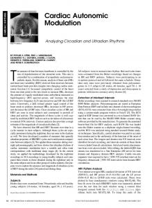
Fig. 1. Schematics showing an SOI lateral bipolar transistor with a positive substrate bias. Left: device cross section. Right: energy-band diagram along a cut from p+ extrinsic base to SOI substrate.
as a dynamic threshold voltage MOSFET (DTMOS) [5]. DTMOS is typically operated at Vdd < 0.5 V to avoid excessive gate current. In theory, an MOSFET can be operated as a bipolar transistor with the MOSFET gate electrode not tied to the body/base but held at a fixed voltage. The operation of such bipolar transistors has not been studied in any depth [1]–[4]. One possible explanation could be that the devices studied were built using a relatively thin gate insulator. They were built as an MOSFET and then operated in a mode to improve their current–voltage characteristics. From a device structure perspective, a symmetrical SOI lateral bipolar transistor can be viewed as an MOSFET as well. This is shown in Fig. 1 for an SOI lateral n-p-n bipolar transistor. When viewed as a bipolar transistor, the device terminals are emitter (E), base (B), and collector (C). When viewed as a bulk FET, the device terminals are source (S), gate (SOI substrate), drain (D), and FET body (X). The characteristics of symmetric SOI lateral bipolar transistors with the SOI substrate at zero bias or floating [see Fig. 1 (left side)] have been studied in detail [6]–[11]. Model simulation results suggest that the transistors are capable of achieving the logic gate delays of 1 THz. The measured collector and base currents can be described well by a 1-D transport model that is valid for all current injection levels [9]. The SOI substrate offers a fourth device terminal where a voltage can be applied to influence the bipolar transistor characteristics. With a positive bias on the FET gate (SOI substrate), the FET surface (near the BOX) is depleted, as shown in Fig. 1. It should be noted that the operation of the device in Fig. 1 is distinctly different from the operation of a body-gate-tied
0018-9383 © 2016 IEEE. Personal use is permitted, but republication/redistribution requires IEEE permission. See http://www.ieee.org/publications_standards/publications/rights/index.html for more information.
1836
IEEE TRANSACTIONS ON ELECTRON DEVICES, VOL. 63, NO. 5, MAY 2016
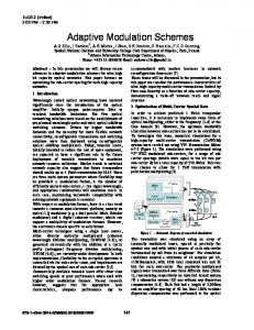
Fig. 2. Typical effect of a positive substrate bias (from 0 to 15 V) on the collector current (left) and base current (right) of a symmetric Si-OI lateral n-p-n transistor. The currents were measured at VBC = 0. The transistor has N E = 2e20 cm−3 and N B = 2.5e18 cm−3 . The BOX thickness is ∼140 nm.
SOI MOSFET as a bipolar transistor. In Fig. 1, the SOI substrate is not connected to the base of the bipolar transistor. Instead, the SOI substrate is held at a fixed voltage during the operation of the bipolar transistor. In this paper, we examine the effect of SOI substrate voltage on the current–voltage characteristics of symmetric SOI lateral bipolar transistors. We also explore the benefit of using substrate voltage as a knob for enhancing the performance of bipolar circuits. II. E XPERIMENTAL R ESULTS In this section, we show the effect of the substrate bias on typical symmetric SOI lateral bipolar transistors for various measurement configurations. In-depth discussion of the physical mechanisms will be deferred to Section III. A. Gummel Currents Measured at V BC = 0 Fig. 2 shows the typical results of applying a positive substrate bias to an n-p-n transistor. It shows that the collector current can be increased by a large amount, especially at small VBE . The base current, on the other hand, is insensitive to the positive substrate voltage. Qualitatively, this can be understood from the energy-band diagram in Fig. 1. The positive substrate voltage causes the base region near the BOX to be depleted, resulting in a lowering of the barrier for electron injection from the emitter into the base region. The positive substrate voltage causes accumulation in the emitter region near the BOX, which has little effect on the barrier for hole injection from the base into the emitter. A more in-depth discussion of the physical mechanisms is deferred to Section III. Fig. 3 shows the typical results of applying a negative substrate bias to the same n-p-n transistor in Fig. 1. It shows a slightly decreased collector current at large negative bias. The negative voltage turns the base region near the BOX into accumulation, resulting in just a slight increase in the barrier adjacent the BOX for electron injection into the base. The measured currents show no noticeable dependence on negative substrate bias. As expected, similar results were observed for symmetric SOI lateral p-n-p transistors, as shown in Fig. 4. For p-n-p transistors, a negative substrate bias can increase the collector current by a large amount with little change to the base current.
Fig. 3. Effect of negative substrate bias (from 0 to −15 V) on the collector current (left) and base current (right) of the n-p-n transistor in Fig. 2. The currents were measured at VBC = 0.
Fig. 4. Typical effect of a negative substrate bias (from 0 to −15 V) on the collector current (left) and base current (right) of a symmetric Si-OI lateral p-n-p transistor. The currents were measured at VBC = 0.
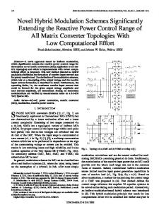
B. Gummel Currents Measured at Fixed VC E The currents in Figs. 2 and 4 were measured at VBC = 0. As a result, the measured current precipitously drops off to zero as VBE approaches zero. With VBC = 0, the measured currents do not contain any leakage currents originating from the base–collector diode. Fig. 5 shows the typical results of applying a positive substrate bias to an n-p-n transistor (the same device as in Fig. 2) with the currents measured at fixed VCE . At a fixed VCE , the collector–base diode is reverse-biased when VBE is less than VCE and any collector–base diode leakage current will add to the collector current (causing the measured collector current to increase) and from the base current (causing the measured base current to decrease). The measured currents in Fig. 5 show little dependence on VCE , and no noticeable increase in collector current at small VBE , suggesting that the measured device has relatively small leakage current originating from its reverse-biased base–collector diode. Again, a more in-depth discussion of the physical mechanisms is deferred to Section III. Fig. 6 compares the measured currents for a SiGe-OI n-p-n transistor, taken with VBC = 0 (left) with those taken with VCE = 0.9 V (right) for several positive Vx values. In both the plots, the base currents are relatively insensitive to Vx , as expected. Based on a previous study [10], the SiGe-OI transistor in Fig. 6 is known to have relatively large residue implant damage in the emitter–base and collector– base diodes, leading to large space-charge-region recombination base current and large collector–base diode reverse-bias leakage current. The large recombination base current can be seen from the 120 mV/decade base current on the VBC = 0
YAU et al.: SUBSTRATE-VOLTAGE MODULATION OF CURRENTS IN SYMMETRIC SOI LATERAL BIPOLAR TRANSISTORS
Fig. 5. Effect of a positive substrate bias (from 0 to 15 V) on the collector current (left) and base current (right) of the n-p-n transistor in Fig. 2. The currents were measured at VCE of 0.5 and 1.5 V. For example, the label 10(1.5) is for currents measured at Vx = 10 V and VCE = 1.5 V.
1837
Fig. 7. Effect of a positive substrate bias (Vx = 10 V) on the output characteristics of the n-p-n transistor in Fig. 2. The characteristics were measured at base-current steps of 2 μA/step (left) and 1 nA/step (right).
in Fig. 7 suggest well-behaved bipolar transistors, while the Early voltage is a function of the base-current steps. The Early voltage is ∼5 V when measured at 2-μA base-current steps [Fig. 7 (left)], and ∼ 0.75 V when measured at 1-nA base-current steps [Fig. 7 (right)]. III. P HYSICAL M ECHANISMS
Fig. 6. Typical effect of a positive substrate bias (from 0 to 20 V) on the collector and base currents taken at VBC = 0 (left) and taken at VCE = 0.9 V (right) for a symmetric SiGe-OI lateral n-p-n transistor. The transistor has N E = 4e20 cm−3 and N B = 2.5e18 cm−3 . The BOX thickness is ∼140 nm.
plot at small VBE . The large diode leakage current can be seen from the VCE = 0.9 V plot where the base current turns negative at VBE below about 0.6 V, and the collector current is equal to the base current in magnitude at small VBE (for the cases of Vx = 0 and Vx = 15 V). This should be contrasted with the Si-ON n-p-n device in Fig. 5, which has negligibly small collector–base diode leakage current. The net is that the currents measured at fixed VCE can be rather complex for devices with appreciable collector–base diode leakage current. C. Output Characteristics The output characteristics (collector current as a function of VCE ) of a bipolar transistor are typically measured at fixed base-current steps. The data in Figs. 2 and 5 show that the base current is not affected by a substrate bias. They also suggest that the output characteristics measured at large basecurrent steps, where the effect of Vx is relatively small, should behave very differently than those measured at small base current steps, where the effect of Vx is large. This is shown in Fig. 7, which compares the output characteristics with and without a positive substrate bias for the same n-p-n device in Figs. 2 and 5. As can be seen from Figs. 2 and 5, I B is 2 μA at VBE about 1 V and 1 nA at VBE about 0.75 V for this device. Fig. 7 shows little effect of substrate bias when measured at 2-μA base-current steps, and pronounced effect when measured at 1-nA base-current steps, consistent with the current plots in Figs. 2 and 5. The output characteristics
As shown in Fig. 1, when a positive substrate bias is applied to an n-p-n transistor, the base region near the BOX is depleted. Considering the case at thermal equilibrium with VBE = VBC = 0, the surface potential ψs is given by Vgx − Vfb = ψs +
εsi Em Cox
(1)
where Vgx (=Vx ) is the substrate bias (potential difference between the SOI substrate and the base terminal), Vfb is the flat-band voltage (approximately zero for the devices using p-type substrate), Cox is the capacitance per unit area for the BOX layer, and E m is the maximum electric field in the silicon, which is located at the silicon/BOX interface. For our devices with the BOX thickness of ∼140 nm and N B = 2.5e18 cm−3 , ψs is 150 mV for Vx = 15 V. The corresponding depletion region depth Wd is 8.8 nm. The SOI silicon thickness is ∼60 nm. That is, at Vx = 15 V, ∼15% of the base region next to the BOX becomes lightly depleted. Fig. 8 is a schematic, showing the cross sections of an n-p-n transistor and its quasineutral regions with Vx = 0 (left) and with Vx > 0 (right). When Vx = 0, there is a quasineutral base region extending from the extrinsic base to the BOX. There is a depletion region between the quasineutral base and the emitter and a depletion region between the quasineutral base and the collector. When Vx > 0, there is an additional depletion region adjacent the BOX. A. Case of Vx = 0 and Base Width Modulation The quasineutral base width of a symmetrical SOI lateral bipolar transistor is modulated by the base voltage, through the modulation of the depletion layer width, from both the emitter end and from the collector end. At large VBE where the density of free carriers is large, the free carriers add to the base width modulation, through the dependence of the space-charge layer width on space-charge density, from both the emitter end and from the collector end as well [7], [9].
1838
Fig. 8. Schematic cross section showing the quasineutral regions of an n-p-n transistor. When a positive substrate bias is applied (right), a depletion region of width Wd (as suggested in Fig. 1) is formed in the base region near the BOX. The electrons injected from the emitter tend to turn and flow toward the BOX instead of horizontally toward the collector region.
IEEE TRANSACTIONS ON ELECTRON DEVICES, VOL. 63, NO. 5, MAY 2016
leakage current. For devices with negligible collector–base diode reverse-bias leakage current, e.g., the Si-OI device in Fig. 5, the device OFF current is simply determined by the FET current component, which is a function of Vx . For example, the device in Fig. 5 shows a device OFF current of ∼0.5 μA for Vx of 15 V, and ∼0.3 nA for Vx of 10 V. On the other hand, the SiGe-OI device with relatively large diode leakage in Fig. 6 shows a device OFF current of ∼100 nA for Vx values 0), both the base–emitter diode space-charge region and the base–collector diode space-charge region shrink and a quasineutral base region starts to form. B. Electron Flow in an n-p-n With Vx > 0 When Vx > 0, the collector current has two components, a component from the remaining quasineutral region of the base and a component from the lightly depleted base region. Fig. 8 suggests that the electron transport from emitter to collector cannot be described by a 1-D model. Furthermore, the electrons injected into the quasineutral base region, i.e., electrons arriving at a location x > Wd in Fig. 8, can diffuse toward the BOX and reach the surface space-charge region instead of reaching the base–collector diode spacecharge region. For these electrons, the effective quasineutral base width is much smaller than W B . The implication is that the electrons injected from the emitter into the quasineutral base region result in a larger collector current when Vx > 0 and then when Vx = 0. In addition, as shown in Fig. 8, the electrons from the emitter can be injected directly into the lightly depleted region near the BOX. Electron for electron, the electrons injected directly into the lightly depleted region contribute more to the collector current than the electrons injected into the quasineutral region. The net is that for a given VBE , the measured collector current is greatly increased by the positive substrate bias, and a 2-D numerical model is needed to quantitatively describe the currents. C. Device OFF Current at V B E = 0 and Vx > 0 The device current at VBE = 0 and Vx > 0 is the sum of the FET current and the collector–base diode reverse-bias
In a bipolar transistor design, it is desirable to have large current gains. A common approach to achieve a large current gain is to employ a heterojunction bipolar transistor (HBT) structure, with the emitter energy gap larger than the base energy gap. The collector current is determined by the base. Therefore, for a fixed VBE , the collector current can be increased by using a smaller energy gap semiconductor for the base region. The recently reported SiGe-OI lateral bipolar transistors [10] demonstrated more than 100× the larger collector current, at the same VBE , compared with a Si-OI transistor with comparable design parameters. However, since the emitter was also SiGe and not Si, the base current was also much larger than that of a Si-OI transistor. What is really desired is a narrow-gap-base HBT structure, having Si as emitter and a smaller gap semiconductor (e.g., SiGe) as base [12]. Such an HBT is expected to show the same base current as a Si-OI device but much larger collector current. At the time of this study, such a lateral HBT on SOI has not been reported. The data reported in this paper demonstrate that the substrate terminal can be used to greatly increase the current gain of an SOI lateral bipolar transistor, by increasing its collector current without changing its base current. As long as the BOX is not too thin, e.g., thicker than about 20 nm, the application of a substrate bias to an SOI lateral transistor does not change its device capacitance. What needs to be demonstrated through experiment and/or quantitative modeling is the circuit-level benefit of using substrate bias to increase the current gain. Here, we qualitatively examine two examples where substrate bias could be beneficial. The performance–power characteristics for a Si-OI complementary bipolar inverter without substrate bias have been studied [13]. In [13], the model assumes both the n-p-n and the p-n-p devices to have the same collector current dependence on VBE . In practice, the collector currents of the two devices are different even though they are integrated on the same chip [9]. A blanket substrate could be employed to equalize the n-p-n and p-n-p collector currents. A blanket positive substrate bias will increase the n-p-n collector current without changing the p-n-p collector current, while a blanket negative substrate bias will increase the
YAU et al.: SUBSTRATE-VOLTAGE MODULATION OF CURRENTS IN SYMMETRIC SOI LATERAL BIPOLAR TRANSISTORS
p-n-p collector current without changing the n-p-n collector current. Another example where substrate bias could be beneficial is for integrated injection logic (I2 L) circuits built in SOI lateral bipolar [7]. I2 L is by far the densest circuit. It uses minimumsize devices, and requires one p-n-p per gate for current injection and one n-p-n per fan-out. Thus, an FO = 3 circuit has just four transistors. The number of fan-outs is limited by the current gain of the n-p-n transistor. Thus, a blanket positive substrate bias, which increases the n-p-n current gain but has little effect on the p-n-p, should enable I2 L gates having large fan-outs to be used. While it has not been demonstrated, the collector current enhancement from substrate bias is expected for true narrowgap-base HBT (such as SiGe-base and Si-emitter) as well. That is, the current gain of an SOI lateral narrow-gap-base HBT could be further improved by a large factor with substrate bias. V. C ONCLUSION The substrate of an SOI symmetric lateral bipolar transistor can be used as a fourth device terminal to improve the collector current by a large factor, with little effect on the base current. A positive substrate bias increases the current gain of an n-p-n transistor, with little effect on a p-n-p transistor sharing the same substrate. A negative substrate bias increases the current gain of a p-n-p transistor, with little effect on an n-p-n transistor sharing the same substrate. There are plenty of opportunities for enhancing SOI lateral bipolar circuits by applying substrate bias. R EFERENCES [1] J.-P. Colinge, “An SOI voltage-controlled bipolar-MOS device,” IEEE Trans. Electron Devices, vol. ED-34, no. 4, pp. 845–849, Apr. 1987. [2] S. Verdonckt-Vandebroek, S. S. Wong, and P. K. Ko, “High gain lateral bipolar transistor,” in IEDM Tech. Dig., Dec. 1988, pp. 406–409. [3] S. Verdonckt-Vandebroek, S. S. Wong, J. C. S. Woo, and P. K. Ko, “High-gain lateral bipolar action in a MOSFET structure,” IEEE Trans. Electron Devices, vol. 38, no. 11, pp. 2487–2496, Nov. 1991. [4] S. A. Parke, C. Hu, and P. K. Ko, “Bipolar-FET hybrid-mode operation of quarter-micrometer SOI MOSFETs (MESFETs read MOSFETs),” IEEE Electron Device Lett., vol. 14, no. 5, pp. 234–236, May 1993. [5] F. Assaderaghi, S. Parke, D. Sinitsky, J. Bokor, P. K. Ko, and C. Hu, “A dynamic threshold voltage MOSFET (DTMOS) for very low voltage operation,” IEEE Electron Device Lett., vol. 15, no. 12, pp. 510–512, Dec. 1994. [6] J. Cai et al., “Complementary thin-base symmetric lateral bipolar transistors on SOI,” in IEDM Tech. Dig., Dec. 2011, pp. 16.3.1–16.3.4.
1839
[7] T. H. Ning and J. Cai, “On the performance and scaling of symmetric lateral bipolar transistors on SOI,” IEEE J. Electron Devices Soc., vol. 1, no. 1, pp. 21–27, Jan. 2013. [8] J. Cai et al., “SOI lateral bipolar transistor with drive current >3 mA/μm,” in Proc. IEEE S3S Conf., Oct. 2013, pp. 1–2. [9] J. Cai et al., “On the device design and drive-current capability of SOI lateral bipolar transistors,” IEEE J. Electron Devices Soc., vol. 2, no. 5, pp. 105–113, Sep. 2014. [10] J. B. Yau et al., “SiGe-on-insulator symmetric lateral bipolar transistors,” in Proc. IEEE S3S Conf., Oct. 2015, pp. 1–2. [11] J.-B. Yau, J. Cai, and T. H. Ning, “On the base current components in SOI symmetric lateral bipolar transistors,” IEEE J. Electron Devices Soc., accepted for publication. [12] T. H. Ning, “A perspective on future nanoelectronic devices,” in Proc. VLSI-TSA, Apr. 2013, pp. 1–2. [13] T. H. Ning and J. Cai, “A perspective on symmetric lateral bipolar transistors on SOI as a complementary bipolar logic technology,” IEEE J. Electron Devices Soc., vol. 3, no. 1, pp. 24–36, Jan. 2015.
Jeng-Bang Yau received the Ph.D. degree in electrical engineering from Princeton University, Princeton, NJ, USA, in 2002. He joined the IBM Research Division, Thomas J. Watson Research Center, Yorktown Heights, NY, USA, in 2006, where he has been involved in innovative FDSOI CMOS technologies. He is currently actively engaged in various advanced research works, including the SOI lateral bipolar transistors.
Jin Cai received the B.S. degree in physics from Fudan University, Shanghai, China, and the M.S. and Ph.D. degrees in electrical engineering from the University of Florida, Gainesville, FL, USA. He was with the IBM T. J. Watson Research Center, Yorktown Heights, NY, USA, from 2000 to 2015. In 2015, he joined Taiwan Semiconductor Manufacturing Company, Hsinchu, Taiwan.
Tak H. Ning (M’75–SM’81–F’87) received the Ph.D. degree from the University of Illinois at Urbana–Champaign, Champaign, IL, USA, in 1971. He joined the IBM Thomas J. Watson Research Center, Yorktown Heights, NY, USA, in 1973, where he is an IBM Fellow. Dr. Ning is a member of the National Academy of Engineering and a fellow of the American Physical Society.